Due to unstable voltage in houses and apartments, people are forced to install voltage stabilizers (hereinafter referred to as SV) to power the entire home or to operate a specific device. As with any other type of electrical appliance, sometimes a situation arises when the voltage stabilizer does not work (broken). Internal faults in most cases are associated with power circuits: relays, triacs, servo drive control unit, etc. Therefore, before you begin to analyze the malfunction and the cause of its occurrence, you need to understand what type of stabilizer you have failed. We examined popular types of devices and the principle of their operation separately: . In this article we will look at what types of voltage stabilizer malfunctions there are, why they occur and how to fix them yourself (if possible).
Hum and clicks
If the voltage regulator is humming a lot, you need to check that the supply voltage is not above or below the permissible ranges. The adjustment range in most cases lies within 100-250 Volts.
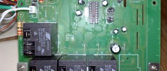
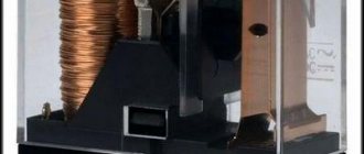
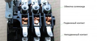
Attention! Even when in good condition, the autotransformer hums evenly and not too loudly. The servo drive also makes a hum when the brush assembly moves. Relay voltage stabilizers make clicking noises during operation. This is normal, the relays (black rectangles in the picture below) switch taps from the windings to regulate the output voltage.
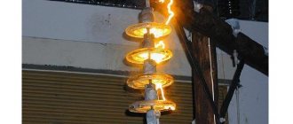
If the device makes a loud noise, this may indicate sparking of the brush in servo-driven models, problems with the relay, and poor contact of the internal wiring of the device.
The stabilizer is going crazy
Good day! The problem is this: A Resanta voltage stabilizer is installed in the house, rated at 8 kilowatts. Every evening for a month, at about 10 pm, something starts to click, switching something inside. At the same time, the light blinks a little (brighter or dimmer) and, accordingly, there is a clicking sound. When you turn on the load (for example, an electric stove), the voltage drops slightly and the clicking stops. The screen shows that the input voltage at this moment is dancing around 235-242 volts, the output is exactly 220. But since the light is blinking, I think it’s pindit. Question: what could it be? Jambs somewhere on the line or a malfunction of the stabilizer itself? And how to deal with this? And is it necessary?
Shuts down under load
The voltage stabilizer does not support the load - this problem happens for a number of reasons. The first among them is increased load (consumer power). If you have not changed the connected devices, then the problem is in the stabilizer. If it does not turn off instantly, but after some time of operation, then this may be due to overheating or interturn short circuits of the autotransformer.
What to do: disassemble the device and carry out an external inspection of the windings of the autotransformer; if it is not too dusty, then check for signs of local overheating. If there is a lot of dust, clean it out
If there are signs of overheating and burning, the insulation of the windings is damaged. This is an interturn short circuit, then how to repair the stabilizer in this case? It is necessary to rewind or replace the autotransformer with one of the same or greater power. But the cost of such repairs can be comparable to purchasing a new voltage stabilizer.
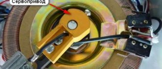
Important! In servo-drive models, a number of malfunctions can be caused by brush wear and contamination of live parts with graphite shavings. During operation, the brush wears off, covering the autotransformer with graphite. Because of this, short circuits between current collectors and sections of turns and overheating can occur. In this case, you need to sweep away the graphite and clean it between turns. Make sure that the windings are laid evenly and there are no breaks. Clean the contact surface with a regular office eraser until it shines, especially the most used sector.
Damage diagnostics
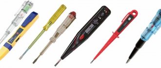
Repair of voltage stabilizers begins with an assessment of its feasibility. If the voltage at the output of the device is zero, this does not mean that the problem lies with it. Perhaps the voltage does not reach the stabilizer itself, so the first thing you need to do is make sure it is present at the input terminals. This can be done using any voltmeter or 220 V light bulb.
If this is not the problem, then you should remove the stabilizer cover. First, it is strictly necessary to turn off the input circuit breakers and make sure that there is no voltage coming to the device. Then you should inspect the stabilizer for burning of the control board tracks, darkening of the wires, relays and their contacts, or destruction of the graphite brushes.
It would be a good idea to take a sniff. If you smell a burning smell, you should, if possible, find out its source. Often this is a direct indication of the cause of the breakdown.
There is no 220 Volt output
The malfunction manifests itself in the fact that the stabilizer does not produce a voltage of 220 Volts. This does not necessarily indicate internal problems, the reason may be the mains voltage - it is too low, and the device simply does not pull. If the power is in the operating range of the stabilizer, then we will proceed with the repair.
What to do: in servo-driven models, failure can be caused by wear of the brush mechanism or the servo drive itself. It may not reach the end of the winding or the brush may not be in contact with its corresponding sector. In the simplest case, it may simply be contaminated with graphite. To repair it, you need to clean the surface of the contacts to a metallic shine. Sometimes you need to replace the brush.
Interesting! It also happens that due to contamination of the working sector of the brush assembly with graphite, the voltage often does not rise above a certain value.
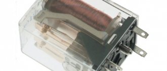
In relay MVs, this most often indicates that one or more electromagnetic relays or their control cascade is faulty. It is usually built on a transistor. Relays can have different coil voltages, often 12 volts.
What to do: to check, apply voltage to the coil and ring the power contacts. They should close and open, the relay clicks. If this does not happen, either the contacts have stuck (more often), or the relay coil has burned out (less often). If the relay is working properly, check the transistor; it should not be broken, and the emitter-base and collector-base junctions should ring in one direction, like a diode. Use any low-power transistors of similar conductivity.
In triac and thyristor MVs, the fault diagnosis is similar - you need to test the semiconductor power switch for breakdown and, if it fails, replace it with an analogous or more powerful one.
The principle of operation of the stabilizer
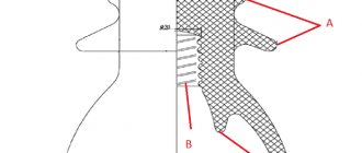
Since only relays are capable of clicking in the stabilizer, it means that it is made according to a relay circuit. Each relay stabilizer has an autotransformer in its structure that increases or decreases the voltage based on the ratio of the turns of the windings. When the voltage value approaches the upper limit of the range, the device circuit switches to the autotransformer winding with a lower voltage value, and, as a result, the output voltage becomes lower. In the same way, this works in the opposite direction: when the voltage in the network deviates towards the lower threshold, the stabilizing device switches to the step-up winding of the autotransformer.
The process of switching the transformer windings is supervised by a special device - the stabilizer controller, and the switching is made through a set of power relays. It is these relays that, at the moment of connection, produce the very clicks that the user hears.
A standard stabilizer can contain from four to seven power relays. And the more voltage surges in the power supply network, the more often switching occurs and clicks are heard. Also, at these moments, the light may blink and highly sensitive equipment may turn off.
There may be several reasons for regular stabilizer clicks:
- Failure of one of the power relays. Since the relay has a limited switching resource, when it is exhausted, the contacts begin to burn and the contact resistance increases. This provokes a large voltage drop at the output of the stabilizer, and the greater the load, the greater the drawdown. Trying to correct the situation, the controller begins to switch to the next stage, where the voltage is actually higher and the controller has to switch again to the previous relay. In this way, a vicious circle of switching and clicking is formed.
- Poor condition of the electrical supply network. These could be poor contacts, the presence of many twists, or a long line with a small number of conductor sections. When trying to connect a load through a stabilization device, the mains voltage decreases at the moment of connection. Having detected this moment, the stabilizer begins to try to increase it by switching to a higher voltage autotransformer winding. But at the moment of connection, the consumer power circuit is disconnected for seconds and the mains voltage returns to its normal level. Noticing this, the stabilization device switches again to the previous level of the circuit. This creates an endless cycle of switching between power relays.
- There is a problem with the control circuit (controller). The problem is individual due to differences between the circuits for each individual stabilizer. However, typically the controller must have some offset to avoid constant tripping within certain voltage values.
Continuous clicking can lead to rapid failure of the device. Since relays are not designed for this mode of operation, the contacts can quickly burn or stick. Sticking will either lead to the burnout of the fuse at the input or to the fact that increased voltage will be supplied to the output of the stabilizer, which can lead to the failure of consumer devices.
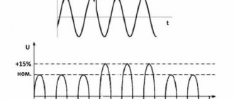
Graphic display of the main operating modes of voltage stabilizers
In one of the previous articles, voltages were described and also brought to the network with your own hands. This material outlines the main problems with voltage stabilization devices and the possibility of repairing them yourself.
It must be remembered that a stabilizer of any type is a complex electrical or electromechanical device with many components inside, therefore, in order to repair it with your own hands, you must have a fairly deep knowledge of radio engineering. Repairing a voltage stabilizer also requires the availability of appropriate measuring equipment and tools.
Complex stabilizer device
Poor voltage stabilization
If the voltage stabilizes in too large steps, and before everything was smooth, then the breakdown is close to the previous one - the switching device has failed at one or more adjustment stages. The algorithm for checking voltage stabilizer malfunctions and their elimination are described in the previous paragraph.
Attention! The characteristics of each stabilizer describe either the adjustment step or the boundaries of each stage, as well as the accuracy of maintaining the rated output voltage.
In servo-drive stabilizers, this occurs when there is a breakdown in the engine gear mechanism, as well as when the windings are dirty, as was the case in the cases described above. Gearbox malfunctions may be accompanied by an uneven buzzing or crackling sound - this is the gears slipping.
What to do: you need to disassemble the mechanism and if all parts are normal, replace the lubricant.
It is also worth noting that servo-driven MVs may lack stabilization and may not work correctly due to the failure of the semiconductor motor control switches. Then the slider with the brush moves to one of the extreme positions or does not move at all.
Basic faults
Due to unstable voltage in houses and apartments, people are forced to install voltage stabilizers (hereinafter referred to as SV) to power the entire home or to operate a specific device. As with any other type of electrical appliance, sometimes a situation arises when the voltage stabilizer does not work (broken). Internal faults in most cases are associated with power circuits: relays, triacs, servo drive control unit, etc.
Having examined the operating principles of both types of voltage stabilizers, we can conclude that it is their main components that are the most frequently broken components of the system. We are talking about a servo drive in electromechanical devices, as well as relays in relay devices.
Due to unstable voltage in houses and apartments, people are forced to install voltage stabilizers (hereinafter referred to as SV) to power the entire home or to operate a specific device.
As with any other type of electrical appliance, sometimes a situation arises when the voltage stabilizer does not work (broken). Internal faults in most cases are associated with power circuits: relays, triacs, servo drive control unit, etc.
The machine does not turn on or crashes after the timer report
Most stabilizers do not enter operating mode immediately after switching on, but after a temporary delay. But after the report, the start-up timer does not occur, and the display indicator shows the letter N. An example of repairing a device with such a malfunction is discussed in the following videos:
For your information, the error code “H” indicates that the network voltage is too high and the protection has tripped. This is valid for devices, "Luxeon" and some others.
Interesting: the letter “H” means “High” or “High”, and L means “low”, “Low”. The resistor, the replacement of which you saw in the video, is responsible for the response thresholds for the upper and lower voltage levels. Due to incorrect resistance, the stabilization board cannot do its job and goes into protection.
Such symptoms or another malfunction code may be accompanied by the breakout of the circuit breaker supplying the stabilizer itself after the turn-on delay timer reports. In this case, the problem is solved by replacing the relays, which, if stuck, may result in increased current consumption.
Exceeding the permissible current
It would seem that when purchasing almost any electrical equipment, one of the most important parameters is its power. And yet, users manage to choose the wrong model due to a negligent attitude to this issue. The voltage stabilizer becomes the power source for your equipment, so the choice of its power and other characteristics should be approached as seriously as possible. If the voltage stabilizer constantly turns off, it is possible that the current protection is triggered. Modern stabilizers usually have two levels of protection. If the current is slightly exceeded, electronic protection is triggered after a certain time. The beating of the machine, in turn, often indicates an avalanche-like current surge, which is typical for short circuits.
Repair of equipment
The absence of problems during the operation of voltage stabilizers will also depend on the quality of their repair. You should not carry out such work yourself or trust it to dubious craftsmen. You should not save on repairs - this will ensure that there are no problems with Resant stabilizers in the future.
In workshops, for diagnosing breakdowns and repairing equipment, a special device LATR is used - a laboratory autotransformer of controlled current. The failed stabilizer is connected to the tester, and voltage is supplied to the rectifier, which allows you to determine equipment failures.
Repair of relay devices
Repair of Resanta devices often involves replacing the relay. In devices from this manufacturer there are usually 4 or 5 of them. Restoring devices of this type is aggravated by the fact that in low-power stabilizers the relay housing is made of opaque plastic. Therefore, it is impossible to visually determine the state of its contacts. Also, low-power relays are non-removable; you cannot simply remove the cover from them.
Additional Information. Just because a relay clicks as expected does not mean it is working properly. The mechanical part of this component may be fine, but it will still not perform its function due to carbon deposits on the contacts.
The second unfavorable factor is that most of the time the input voltage of the stabilizer is in a narrow range. Therefore, basically the same relays are activated. Most often they are located nearby and are subject to the most frequent failures.