What is a thermistor?
A regular resistor has a relatively stable resistance. Of course, the electrical resistance of a conventional resistor can change when it is significantly heated (within tolerances). But in normal mode, the readings of these devices are stable, which is what the developers are striving for.
In the manufacture of thermistors, materials are deliberately selected whose resistance depends on temperature. That is, a thermistor is a semiconductor device whose resistance depends on temperature. It can be said that by heating or cooling such semiconductor devices, their resistances can be controlled.
Rice. 1. Thermistor and its image on the diagrams
The temperature dependences of semiconductor resistors are widely used in practice, which will be discussed below. Let us only note that thermistors are, in fact, variable resistors, the resistance of which does not change mechanically, but depends on the degree of heating and the temperature characteristics of the semiconductor materials used. Moreover, it does not matter whether the temperature indicators changed due to direct or indirect heating.
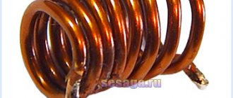
Resistor MMT-4
The directory of precious metal content in radio components was created on the basis of reference data from organizations involved in the processing of scrap radio components, device passports, forms, labels and other open sources. It is worth noting that the actual content may differ by 20-30% downwards.
Content
Content of precious metals in the resistor: MMT-4
Gold: 0 Silver: 0.0150 Platinum: 0 MPG: 0 According to: Handbook of Precious Metals ORDER No. 70
Fixed resistors contain only silver, which is deposited on the terminals. With variable resistors everything is better, they can contain gold, silver, platinum and palladium alloys. Pretentious variable resistors are especially rich in precious metals.
The resistance of a resistor is its main characteristic. The basic unit of electrical resistance is the ohm (Ω). In practice, derivative units are also used - kiloohm (kOhm), megaohm (MOhm), gigaohm (GOhm). Precious metals are mainly found in variable and construction resistors, and palladium is often used in them in the form of runners or flux wires.
Types of resistors
There are three main types of resistors: A variable resistor is a resistor in which the electrical resistance between the moving contact and the terminals of the resistive element can be changed mechanically. Fixed resistors, the resistance of this resistor cannot be changed. As a rule, they have only two outputs. These resistors can only contain silver, in the form of silver-plated leads. Nonlinear. The resistance of components of this type changes under the influence of temperature (thermistors), light radiation (photoresistors), voltage (varistors) and other quantities.
Main characteristics of resistors
Nominal resistance (Ohm, kOhm, mOhm). Maximum power dissipation (0.25 W, 0.5 W, 1 W, etc.) Tolerance or accuracy class (the permissible spread of resistor parameters depends on this value).
Examples of alphanumeric designation of a resistor
Examples of alphanumeric designations for resistance expressed as an integer: 47 Ohm - 47 R; 47 kOhm – 47 K; 47 MOhm – 47 M. If a decimal fraction is used to express the resistance value, then the order of numbers and letters will be different, for example: 0.47 Ohm – R 47; 0.47 kOhm – K 47; 0.47 MOhm - M 47. If the resistance is expressed as a number other than zero and with a decimal fraction, then the letter in the designation plays the role of a comma, for example: 4.7 Ohm - 4R7; 4.7 kOhm – 4K7; 4.7 MOhm – 4M7. The permissible error is indicated in % and is indicated after the nominal value, for example ±7%, ±10%, ±40%. The accuracy class can be determined by a letter, depending on the manufacturer - Russian or Latin.
Share link:
Liked this:
Like
Similar
Design
The simplest thermistor consists of a temperature-sensitive element, platinum electrodes and nickel leads. This entire structure is enclosed in a sealed housing (the structure diagram is shown in Figure 2).
Metal oxides are used as heat-sensitive materials. To protect the structure, a glass, plastic or metal case is used.
Rice. 2. Design of a simple thermistor
In some cases, copper or platinum is used as the resistive material. These materials have high TCR values for metals in the operating temperature range. However, their use is limited due to the high cost of platinum and its nonlinear transformation.
The use of copper thermistors is limited by the low corrosion resistance of copper. Due to the high thermal conductivity of this metal, copper-based resistive elements are found in models with indirect heating. Suitable for temperatures not exceeding 180 ºC.
Another disadvantage of metal thermal resistances is their inertia, which can reach several minutes. Such designs are not very suitable for maintaining the thermal regime of electrical appliances, but they are ideal as sensors for measuring temperature.
In order to reduce thermal inertia, thermistors are made of microwires, which are enclosed in a glass bulb (see Fig. 3). Such sensors are well sealed, stable, and their inertia does not exceed fractions of seconds.
Figure 3. Thermistor design in a glass bulb
Types of sensors based on semiconductor materials have become widespread. When semiconductors are heated, these materials become saturated with electrons and holes, which leads to a decrease in resistance.
There are designs of flat thermistors (Fig. 4), as well as semiconductor thermistors with a complex structure of the resistive element.
Rice. 4. Design of flat thermistor
Today, more and more often you can find boards on which the SMT mounting method is used. For these purposes, the industry produces SMD thermistors of various ratings (see Fig. 5).
Rice. 5. Thermistors for microelectronics
In most designs, the thermistor element is manufactured using powder metallurgy. For these purposes, the following materials are used:
- chalcogenides;
- metal oxides;
- halides and others.
The outline of resistive elements can be in the form of beads, rods, tubes, plates, etc.
Whatever design you choose, the principle of operation remains the same - the dependence of resistance on temperature. The products differ only in parameters.
Thermistor operating mode
Depending on the design intent, thermistors can operate in systems with different temperature conditions. However, each model has its own nominal temperature scale.
On this basis they can be classified as follows:
- low-temperature class thermistors (up to 170 K);
- products of medium temperature class (used in the temperature range 170 – 510 K);
- high-temperature class models (ranging from 570 K and above).
Thermistors are included in a separate class, capable of operating at temperatures from 900 to 1300 K. These models are used as temperature sensors of various heating elements.
All thermistors can withstand significant current loads. True, when operating in harsh thermal cyclic modes, their thermoelectric characteristics may change. Over time, changes will affect the nominal resistance and resistance coefficient.
Thermistor Series
The following series of direct heated thermistors were produced by the domestic industry.
- ST1 – copper-manganese thermistors (formerly MMT);
- ST2 – cobalt-manganese thermistors (formerly KMT);
- ST3 – copper-cobalt-manganese thermistors;
- ST4 – nickel-cobalt-manganese thermistors;
- ST5 – posistors based on barium titanium doped with germanium;
- ST6 – posistors based on barium titanate (BaTiO3);
- ST8 – thermistors based on vanadium sesquioxide and a number of polycrystalline solid solutions in V2O3-Me2O3 systems (Me=Ti; Al, Cr);
- ST9 – thermistors based on vanadium dioxide VO2;
- ST10 – PTC posistors based on the (Ba, Sr)TiO3 system;
- ST11 – PTC posistors based on the (Ba, Sr)(Ti, Sn)O3 system doped with cerium.
Varieties
All thermistors are classified according to the type of heating: direct and indirect. For direct heating, the current of the circuit in which the thermistor is connected is used. Indirect heating is created by third-party circuit sections or thermal elements.
An example of a direct heated thermistor is shown in Fig. 6.
Rice. 6. Directly heated thermistors
Also, depending on whether the resistance increases or decreases when the resistive element is heated, there are two types of thermistors: with a negative TCR and thermistors with a positive resistance coefficient.
NTC.
Semiconductor models (thermistors) have a negative coefficient of temperature resistance. This means that they reduce the nominal resistance (reading at 25 ºC) as a result of heating. The temperature coefficient shows by what percentage the resistance of a resistive element decreases when the heating temperature increases by 1 ºC.
Negative coefficient NTC thermistors are typically used in the operating temperature range of 25 ºC to 200 ºC. For temperatures above 600 ºC, thermocouples are used.
PTC.
PTC thermistors have positive temperature coefficients. These PTC thermistors are often called posistors to emphasize the positive temperature coefficient. By this term we mean a thermistor, the resistance of which increases with increasing temperature.
Thermistors
Here are the characteristics of small-sized thermistors that can be used in PC temperature control devices and designs you develop.
Thermistors or thermistors (TR) are semiconductor resistors with a nonlinear Volt-Ampere Characteristic (VAC), which have a clear dependence of electrical resistance on temperature. Thermistors with negative and positive Temperature Coefficient of Resistance (TCR) are produced.
Nominal resistance Rн
- electrical resistance, the value of which is indicated on the case or indicated in the regulatory documentation, measured at a certain ambient temperature (usually 20ºC). The values are set according to row E6 or E12.
Temperature coefficient of resistance TKS
- characterizes, as usual, a change (reversible) in resistance by one degree Kelvin or Celsius.
The maximum permissible power dissipation
P max
is the highest power that a TR can dissipate for a long time without causing irreversible changes in characteristics. However, its temperature should not exceed the maximum operating temperature.
Temperature sensitivity coefficient B
— determines the nature of the temperature dependence of this type of TR. Known as the constant B, which depends on the physical properties of the semiconductor material from which the temperature-sensitive element is made.
Time constant t - characterizes thermal inertia.
It is equal to the time during which the resistance of the TR changes by 63% when it is transferred from an air environment with a temperature of 0ºC to an air environment with a temperature of 100ºC.
Thermistors with negative TCS
| Type | Range of nominal resistances at 20ºС, kOhm | Tolerance % | Maximum power 20ºС, mW | Operating temperature range, ºС | TKS at 20ºС, %/ºС | Constant V, K | Time constant t, sec | Type and scope |
| KMT-1 | 22 -:- 1000 | ±20 | 1000 | -60-:-180 | 4,2-:-8,4 | 3600 -:-7200 | 85 | C, T measurements |
| KMT-4 | 22-:-1000 | ±20 | 650 | -60 -:- 125 | 4,2-:-8,4 | 3600 -:-7200 | 115 | C, T measurements |
| KMT-8 | 0,1-:-10 | ±10,±20 | 600 | -60-:-+70 | 4,2-:-8,4 | 3600-:-7200 | 909 | Thermal compensation |
| KMT-10 | 100-:-3300 | ±20 | 250 per current 2sec | 0-:-125 | >4,2 | >3600 | 75 | C, Control T |
| KMT-11 | 100 -:-3300 | ±20 | 250 per current 2sec | 0-:-125 | >4,2 | >3600 | 10 | C, Control T |
| KMT-12 | 100Ohm-:-10 | ±30 | 700 | -60 -:-125 | 4,2 -:-8,4 | 3600-:-7200 | — | D, Meas. - T Comp. |
| KME-14 | 510,680, 910 Ohm 160, 200, 330 KOhm 4.3, 75 MOhm at 150°C | ±20 | 100 | -10-:-300 | 2,1-:-2,5 3,4-:-4,2 3,5-:-4,3 | 3690-:-4510 6120-:-7480 6300-:-7700 | 10-:-60 | B, T measurements |
| KMT-17v | 0,33-:-22 | ±10,±20 | 300 | -60-:-155 | 4,2-:-7 | 3600-:-6000 | 30 | D, T measurement |
| MMT-1 | 12 — :- 220 | ±20 | 500 | -60 -:- 125 | 2,4 -:- 5 | 2060 -:- 4300 | 85 | C, T measurements |
| MMT-4 | 1-:-220 | ±20 | 560 | -60 -:- 125 | 2,4 -:- 5 | 2060 -:- 4300 | 115 | C, T measurements |
| MMT-6 | 10-:-100 | ±20 | 50 | -60 -:- 125 | 2,4-:-5 | 2060-:-4300 | 35 | C, T measurement |
| MMT-8 | 1 Ohm -:- 1 | ±10,±20 | 600 | -60 -:- 70 | 2,4 -:- 4 | 2060-:-3430 | 900 | Thermal compensation |
| MMT-9 | 10 Ohm -: -4.7 | ±10,±20 | 900 | -60 -:- 125 | 2,4-:-5 | 2060-:-4300 | — | D |
| MMT-12 | 0,0047 — 1 | ±30 | 700 | -60 -:- 125 | 2,4-:-4 | 2060-3430 | — | D, Thermal compensation |
| MMT-15 | 750Ohm-:-1.21 | — | — | -60 -:- 125 | 2,6-:-4 | 2230-:-3430 | D | |
| MME-13 | 0,01 — 2,2 | ±20 | 600 | -60 -:- 125 | 2,4-:-5 | 2060-4300 | — | D, Thermal compensation |
| PT-1 | 400 ohm -: -900 ohm | — | — | -60 -:- 150 | 4,1-:-5,1 | 3500-:-4400 | — | D, T measurement |
| PT-2 | 80 Ohm -:- 400 Ohm | ±20 | — | -60 -:- 150 | 4,4-:-4,8 | 3800-:-4100 | — | D, T measurement |
| PT-3 | 400 Ohm -:- 900 Ohm | ±20 | — | -60 -:- 150 | 4,3-:-4,8 | 3700-:-4700 | — | D, T measurement |
| PT-4 | 0,6-:-0,8 | — | — | -60-:-150 | 4,1-:4,9 | 3500-:-4200 | — | D, T measurement |
| ST3-14 | 1,5; 2,2 | ±20 | 30 | -60-:-125 | 3,2-:-4,2 | 2600-:-3600 | 4 | B, T measurement |
| MKMT-16 | 2,7; 5,1 | ±30 | 40 | -60-:-125 | 3,8-:-4,2 | 3250-:-3600 | 10 | B, T measurement |
| ST1-18 | 1.5; 2.2; 22; 33; 1500; 2200 at 150ºС | ±20 | 45 | -60-:-300 | 2.25-:-5 at 150ºС | 4050-:-9000 | 1 | B, T measurement |
| ST3-1 | 0,68 -:- 2,2 | ±10, ±20 | 600 | -60 -:- 125 | 3,35 -:- 3,95 | 2870-:-3395 | 85 | C, T measurements |
| ST3-14 | 1,5; 2,2 | ±20 | 30 | -60 -:- 125 | 3,2-:-4,2 | 2600-:-3600 | 4 | B, T measurement |
| ST3-17 | 33Ohm-:-330 Ohm | ±10, ±20 | 300 | -60 -:- 100 | 3-:-4,5 | 2580-:-3850 | 30 | D, Meas. - T Comp. |
| ST3-18 | 0,68-:-3,3 | ±20 | 15 | -90-:-125 | 2,6-:-4,1 | 2250-:-3250 | 1 | B, T measurement |
| ST3-3 | 6,8; 8,2 | ±10 | 150 | -90-:-125 | 2,8 -:- 3,2 | 1200 -:- 2400 | 35 | C, T measurements |
| ST1-2 | 82, 91,100, 110 ohm | ±5 | 700 | -60-:-+85 | 4,4-:-4,9 | 3800-:-4200 | 60-:-100 | D, T measurement |
| ST1-17 | 330Ohm-:-22 | ±10, ±20 | 300 | -60-:-155 | 4,2-:-7 | 3600-:-6000 | 30 | D, Meas. - T Comp. |
| ST1-19 | 3,3-:-10 | ±20 | 60 | -60-:-300 | 2.35-:-4 at 150ºС | 4230-:-7200 | 3 | B, T measurement |
| ST1-30 | 33 | — | <120 mA heating current | -60-:-85 | 4,2-:-5,1 | 3600-:-4400 | 6-:-12 | Measuring velocities of gases and liquids |
| ST3-19 | 2,2; 10; 15 | ±20 | 45 | -90-:-125 | 3,4-:-4,5 | 2900-:-3850 | 3 | B, T measurement |
| ST3-22 | 1 at 25°C | ±30 | 8 | -60-:-85 | 3,1-:-4,2 | 2700-:-3700 | 15 | B, T measurement |
| ST3-23 | 2.2 ohm -: -4.7 ohm | ±10, ±20 | — | 0-:-125 | 3,1-:-3,8 | 2600-:-3200 | — | D, Thermal compensation |
| ST3-25 | 1,5-:-6,8 | ±20 | 8 | -100-:-125 | 3,05-:-4,3 | 2500-:-3700 | 0,4 | B, T measurement |
| ST3-28 | 150Ohm-:-3.3 | ±20 | — | -60 -:- 125 | 3-:-4,6 | 2580-:-3970 | — | D, Thermal compensation |
| ST4-2 | 2,1-:-3,0 | — | — | -60 -:- 125 | 4,2-:-4,8 | 3170-:-4120 | — | D, Meas. T, auto-tracton engines |
| CT4-15 | 880 Ohm -1.12 | — | — | -60 -:- 125 | 3,4 -:-3,8 | 2350- 3250 | — | D, Meas. T, auto-tracton engines |
| ST4-16 | 10-:-27 | ±5; ±10 | 150 | -60-:-155 | 3,45-:-4,45 | 2720-:-3960 | 30 | B, T measurement |
| ST4-16A | 6,8; 10; 15 | ±1; ±2; ±5 | 180 | -60-:-+200 | 4,05-:-4,45 | 3250-:-4100 | B, T measurement | |
| ST4-17 | 1,5-:-2,2 | ±10 | 500 | -80-:-+100 | 3,8-:-4,2 | 3260-:-3600 | 30 | D, T measurement |
| ST9-1A | 0,15-:-450 | — | 800 | -60-:-+100 | — | 1600-:-2000 | 110 | C, Thermostats |
| TR-1 | 15; 33 | ±10; ±20 | 20; 50 | -60-:-+155 | 3,8-:-4,4 | 3200-:-3900 | 5-:-10 | B, T measurement |
| TR-2 | 15; 33 | ±10; ±20 | 20; 50 | -60-:-+155 | 3,8-:-4,4 | 3200-:-3900 | 5-:-10 | B, T measurement |
| TR-3 | 1,2; 12 | ±10 | 1000 | -60 -:- 125 | 3,9-:-4,8 | 3470-:-4270 | — | D, Reg. sensor T |
| TR-4 | 1 | ±20 | 70 | -60-:-+200 | 1,8-:-2,2 | 1500-:-1960 | 3 | B, T measurement |
TRs have different designs:
| Design | Designation | Appearance |
| rod | WITH | |
| disk | D | |
| beaded | B |
New! Thermistors based on single crystals of semiconductor diamond, type TPA-1, TPA-2.
These are new semiconductor devices that have significant advantages compared to previously produced thermistors.
The use of semiconductor diamond single crystals as thermosensitive elements (TSEs) has significant advantages, which are determined by the following unique properties:
- complete absence of diffusion effects (operability) up to a temperature of about 1000°C;
- exceptional resistance to aggressive environments and radiation;
- absolute hardness,
- low inertia.
| parameter | at | dimension | magnitude | Note | |
| TPA-1 | TPA-2 | ||||
| Nominal resistance | 25°С | kOhm | 0,01 — 10000 | Produced according to: DILS.434121.001 TU, OZh0468051TU | |
| Temperature sensitivity coefficient | -200…+300°С | TO | 300…2500 | 600…6000 | |
| Temperature coefficient of resistance | 25°C | %/deg | -0,2…-2,3 | -0,5…-0,6 | |
| Maximum power dissipation | — | mW | 500 | ||
| Operating temperature range | — | WITH | -200…+330 | ||
| Time constant | — | sec | 1…5 | ||
| Peak acceleration of multiple mechanical shock | — | g | 150 | ||
| Increased atmospheric pressure | — | Pa/kg*cm2 | 297200/3 | ||
| Atmospheric condensed precipitation | — | frost, dew | |||
| Special factors | — | group | 4U | ||
Thermistors of type TRA-1 and TRA-2 can be used in the following electronic devices:
- analogue and digital thermometers with a measurement range from -60°C to 300°C (and operation at maximum temperatures for 500 hours did not lead to a noticeable change in calibration);
- temperature-compensated frequency generators;
- thermostats with different heater power;
- liquid and gas flow meters of hot-wire type;
- minimum liquid level indicators,
- and others where TR with negative TCS is used.
The glass body and massive crystal compared to diamond (~0.2...0.3 mm) significantly limit the maximum operating temperature of the TPA (<400°C) and thermal inertia (> 1 s). In this case, the use of copper wire with a diameter of 0.1 mm as leads makes it possible to reduce the time constant by approximately 2 times.
Experimental designs of unpackaged diamond thermistors are being developed, in which the crystal size is 0.5...0.6 mm, and the diameter of the silver leads is 0.05 - 0.1 mm. For such thermistors, the maximum operating temperature increases to 600°C, and at the same time the thermal inertia decreases by an order of magnitude.
, 601655, Vladimir region, Alexandrov, st. Institutskaya 24, Polyansky E.V.
Directly heated thermistors are voltage stabilizers.
| Type | Nom. voltage, V | Stabilization range, V | Max. voltage changes, V | Average worker current, ma | Current working area, mA | Limit current (2s), ma |
| TP 2/0.5 | 2 | 1,6-:-3 | 0,4 | 0,5 | 0,2-:-2 | 4 |
| TP 2/2 | 2 | 1,6-:-3 | 0,4 | 2 | 0,4-:-6 | 12 |
| TP 6/2 | 6 | 4,2-:-7,8 | 1,2 | 2 | 0,4-:-6 | 12 |
Thermistors with positive TCS, posistors.
| Type | Range of nominal resistances at 20ºС, kOhm | Max. Power, W | Operating temperature range, ºС | The temperature range is positive. TKS, ºС | Max. TKS at 20ºС, %/ºС | Frequency of measurement resistance in the region positive TCS. | Time constant, sec | Purpose |
| ST5-1 | 0,02-:-0,15 | 0,7 | -20-:-+200 | 100-200 | 20 | 1000 | 20 | PP alarm |
| ST6-1A | 0,04-:-0,4 | 1,1 | -60-:-+155 | 40-:-155 | 10 | 1000 (at 25-140°C) | 20 | -«- |
| ST6-1B | 0,18; 0,27 | 0,8 | -60-:-+125 | 20-:-125 | 15 | 1000 (at 25-100°C) | 20 | -«- |
| ST6-4G | 5-:-25 | 0,8 | -60-:-+125 | -20-:-+125 | 2-:-6 | 5-:-15 | 40 | D, T measurement |
| ST6-6B | 5-:-25 | 2,5 | -60-:-+125 | 20-:-125 | 15 | 1000 | 180 | — |
| ST10-1 | 30-:-300 | 0,5 | -60-:-+175 | 100-:-175 | — | — | — | Thermal compensation |
| ST5-2-127V | 15-:-35 Ohm | 3 | -60-:-+60 | 60-:-150 | 15 | 10000 (at 25-160°C) | — | Demagnetization systems for picture tube masks. |
| ST5-2-220V | 20-:-50 Ohm | 3 | -60-:-+85 | 60-:-150 | 15 | 10000 (at 25-160°C) | — |
If you need parameters for special-purpose thermistors, write.
The reference table in full (pdf format) from the reference book below can be downloaded here.
Reference table “Thermistors based on semiconductor diamond single crystals” in
Literature:
1. Handbook of REA developer and designer, Element base, Book II, Moscow, publishing house "Pribor" LLP, 2000?
Based on materials from the reference book and other sources, prepared by A. Sorokin, 2008.
Technical specifications
A wide variety of thermal resistance models are dictated by the needs of the modern electronics industry. The technical parameters of semiconductor-type products make it possible to fully satisfy the demand of manufacturers of radio-electronic and electrical devices.
The main parameters include:
- nominal resistance of the thermistor measured at a temperature of 25 ºC;
- power dissipation (that is, the maximum current at which the stability of the thermistor parameters is ensured);
- operating temperature range for which the thermistor is intended;
- TKS.
Semiconductor thermistors have high sensitivity in combination with negative TCR values. They are easy to manufacture, have tiny sizes, and are easily integrated into microcircuits. All these properties make thermistors indispensable in microelectronics.
Semiconductor thermistors are connected via a bridge circuit. This connection allows you to automatically adjust the required parameters of electrical circuits. Sometimes for these purposes it is necessary to use rather complex automation schemes.
The parameters of metal thermistors are more suitable for electrical devices, in particular, they are used as temperature sensors. They can be seen in water heating systems, or in resistance thermometers. These types of sensors (Fig. 7) are very reliable in operation and have a fairly wide measurement range.
Rice. 7. Temperature sensor
Sensors of this type are connected according to a simple scheme. If calibration or temperature adjustment is required, this is usually done manually using a potentiometer. A simple diagram of connecting a temperature sensor is shown in Fig. 8. By changing the voltage with a potentiometer, you can influence the TCR value. You can visually control the temperature using an ammeter, the scale of which is graduated in degrees.
Rice. 8. Simple diagram for connecting a thermistor
Their scope of application is quite wide - they are used in circuits and temperature stabilization circuits of resistor amplifier systems, as well as in various types of devices and instruments for measurement, regulation and automation (measurement, level control and automatic adjustment of climate (temperature) and fire alarms).
The main characteristics of thermistors include:
- Nominal resistance Rн
- electrical resistance, the value of which is indicated on the case or indicated in the regulatory documentation, measured at a certain ambient temperature (usually 20°C). The values are set according to row E6 or E12.
- Temperature coefficient of resistance TKS
— characterizes a change (reversible) in resistance by one degree Celsius.
- Maximum permissible power dissipation Pmax
— the greatest power that a TR can dissipate for a long time without causing irreversible changes in characteristics. However, its temperature should not exceed the maximum operating temperature.
- Temperature sensitivity coefficient B
— determines the nature of the temperature dependence of this type of TR. Known as the “B constant”, it depends on the physical properties of the semiconductor material from which the temperature-sensitive element is made.
- Time constant t
— characterizes thermal inertia. It is equal to the time during which the resistance of a TR changes by 63% when it is transferred from an air environment with a temperature of 0°C to an air environment with a temperature of 100°C.
The dependence of the current that passes through the thermistor on the voltage applied to it (in the case of temperature equilibrium between the resistor and the environment) is determined by the current-voltage characteristic. Inertia shows how quickly the part will respond to changes in ambient temperature, that is, it determines the rate of change in the resistance of the element. Inertia is directly dependent on the design, size of the resistor and thermal conductivity of the environment. Stability determines the period of time during which an element retains its original properties (during use or storage).
| Range of nominal resistances at 20°C | Permissible deviation, ±% | Maximum power, at 20° C, mW | Operating temperature range, ° C | TCS at 20°С, %/°С | Constant V, K | Time constant t, s | Application area | Appearance | |
| Rod | |||||||||
| KMT-1 | 22 kOhm…1 MOhm | ±20 | 1000 | -60…180 | 4,2…8,4 | 3600…7200 | 85 | Temperature measurement and control, temperature compensation | |
| MMT-1 | 1 kOhm…220 kOhm | 600 | -60…125 | 2.4…5 | 2030…4300 | ||||
| CT3-1 | 680 kOhm…2.2 MOhm | ±10, ±20 | 3.35…3.95 | 2870…3395 | |||||
| KMT-4 | 22 kOhm…1 MOhm | ±20 | 650 | 4.2…8.4 | 3600…7200 | 115 | |||
| MMT-4 | 1 kOhm…220 kOhm | 560 | 2.4…5 | 3060…4300 | |||||
| CT3-6 | 6.8 kOhm, 8.2 kOhm | ±10 | 150 | -90…125 | 2.8…3.2 | 1200…2400 | 35 | ||
| MMT-6 | 10 kOhm…100 kOhm | ±20 | 50 | -60…125 | 2.4…5 | 2060…4300 | |||
| KMT-10 | 100 kOhm…3.3 MOhm | 250 for 2s | 0…125 | ≥4,2 | ≥3600 | 75 | Thermal control | ||
| KMT-11 | 10 | ||||||||
| C9T-1a | 150 Ohm…450 Ohm | 800 | -60…100 | 1600…2000 | 110 | Temperature regulation | |||
| Disk | |||||||||
| CT1-2 | 82 Ohm, 91 Ohm, 100 Ohm, 110 Ohm | ±5 | 700 | -60…85 | 4,4…4,9 | 3800…4200 | 60…100 | TK, temperature measurement and control | |
| CT4-2 | 2.1 kOhm…3.0 kOhm | -60…125 | 4,2…4,8 | 3170…4120 | Temperature measurement | ||||
| CT4-15 | 880 Ohm…1.12 kOhm | -60…155 | 3,4…3,8 | 2350…3260 | |||||
| KMT-8 | 100 Ohm…10 kOhm | ±10, ±20 | 600 | -60…70 | 4,2…8,4 | 3600…7200 | 900 | Temperature compensation | |
| MMT-8 | 1 Ohm…1 kOhm | 2,4…4 | 2060…3430 | ||||||
| MMT-9 | 10 Ohm…4.7 kOhm | 900 | -60…125 | 2,4…5 | 2060…4300 | ||||
| KMT-12 | 100 Ohm…10 kOhm | ±30 | 700 | 4,2…8,4 | 3600…7200 | TK, temperature measurement and control | |||
| MMT-12 | 4.7 Ohm…1 kOhm | 2,4…4 | 2060…3430 | ||||||
| MMT-13 | 10 Ohm…2.2 kOhm | ±20 | 600 | 2,4…5 | 2060…4300 | 100 | |||
| KMT-17v | 330 Ohm…22 kOhm | ±10, ±20 | 300 | -60…155 | 4,2…7 | 3600…6000 | 30 | ||
| CT1-17 | -60…100 | ||||||||
| CT3-17 | 33 Ohm…330 Ohm | 3,0…4,5 | 2580…3860 | ||||||
| CT4-17 | 1.5 kOhm…2.2 kOhm | ±10 | 500 | -80 … 100 | 3,8…4,2 | 3260…3600 | |||
| CT3-23 | 2.2 Ohm…4.7 kOhm | ±10, ±20 | 0 … 125 | 3,1…3,8 | 2600…3200 | TK | |||
| CT3-28 | 150 Ohm…3.3 kOhm | ±20 | -60 … 125 | 3…4,6 | 2580…3970 | ||||
| MMT-15 | 760 Ohm…1.21 kOhm | 2,6…4 | 2230…3430 | TK, temperature measurement and control | |||||
| PT | 80 Ohm…400 Ohm | ±20 | -60 … 150 | 4,4…4,8 | 3800…4100 | temperature measurement and control | |||
| PT-2 | |||||||||
| PT-1 | 400 Ohm…900 Ohm | 4,1…5,1 | 3500…4400 | Automatic control system sensors | |||||
| PT-3 | ±20 | 4,3…4,8 | 3700…4100 | ||||||
| PT-4 | 600 Ohm…800 Ohm | 4,4…4,9 | 3500…4200 | ||||||
| TR-3 | 1.2 kOhm, 12 kOhm | ±10 | 1000 | -60…125 | 3,9…4,8 | 3470…4270 | |||
| Beaded | |||||||||
| KMT-14 | 510; 680; 910 Ohm; 160; 200; 330 kOhm; 4.3; 7.5 MOhm at 150°C | ±20 | 100 | -100…300 | 2,1…2,5 | 3690…4510 | 10…60 | Temperature measurement and control | |
| 3,4…4,2 | 6120…7480 | ||||||||
| 3,5…4,3 | 6300…7700 | ||||||||
| CT3-14 | 1.5; 2.2 kOhm | 30 | -60…125 | 3,2…4,2 | 2600…3600 | 4 | |||
| MKMT-16 | 2.7; 5.1 kOhm | ±30 | 40 | -60…125 | 3,8…4,2 | 3260…3600 | 10 | ||
| CT1-18 | 1.5; 2.2; 22; 33 kOhm; 1.5; 2.2 MOhm at 150°C | ±20 | 45 | -60…300 | 2.25…5 at 150°C | 4050…9000 | 1 | ||
| CT3-18 | 680 Ohm…3.3 kOhm | 15 | -90…125 | 2,6…4,1 | 2250…3520 | ||||
| CT1-19 | 3.3…10; 100; 150 kOhm; 1.5; 2.2 MOhm at 150°C | 60 | -60…300 | 2.35…4 at 150°C | 4230…7200 | 3 | |||
| CT3-19 | 2.2; 10; 15 kOhm; | 45 | -90…125 | 3,4…4,5 | 2900…3850 | ||||
| CT3-22 | 1 kOhm at 25°C | ±30 | 8 | -60…85 | 3,1…4,2 | 2700…3700 | 15 | Variable resistance without moving contact | |
| CT3-25 | 1.5…6.8 kOhm | ±20 | -100…125 | 3,05…4,3 | 2600…3700 | 0,4 | Measurement | ||
| CT4-16 | 10…27 kOhm | ±5; ±10 | 150 | -60…155 | 3,45…4,45 | 2720…3960 | 30 | Temperature measurement, TC | |
| CT4-16a | 6.8; 10; 15 kOhm | ±1; ±2; ±5 | 180 | -60…200 | 4,05…4,45 | 3260…4100 | |||
| TR-1 | 15; 33 kOhm | ±10; ±20 | 20; 50 | -60…155 | 3,8…4,4 | 3200…3900 | 5…10 | ||
| TR-2 | |||||||||
| TR-4 | 1 kOhm | ±20 | 70 | -60…200 | 1,8…2,2 | 1600…1960 | 3 | Temperature measurement and control, TK | |
| Thermistors with negative TCR based on a semiconductor single crystal of synthetic diamond | |||||||||
| Type | Range of nominal resistances at 20°C | Permissible deviation, ±% | Maximum power, at 20° C, mW | Operating temperature range, ° C | TCS at 20°С, %/°С | Constant V, K | Time constant t, s | Application area | Appearance |
| TRA-1 | 0.01…10000 kOhm | ±5; ±10; ±20 | 500 | -200…+350 | 0,2…2,3 | 300…2500 | 1 | Measurement of temperature, liquid or gas flow rate, TK | |
| TRA-2 | 1…100 MOhm | 0,55…6,0 | 600…6000 | ||||||
| Thermistors with negative TCR - microwave power meters | |||||||||
| Type | Resistance at the main operating point, Ohm | Maximum power, mW | Operating temperature range, ° C | Sensitivity at operating point, Ohm/mW | TCS at 20°С, %/°С | Constant V, K | Time constant t, s | Appearance | |
| T8D | 140…160 | 15 | -60…85 | 20…30 | 1500 | 1 | |||
| T8E | 10 | 30…70 | — | ||||||
| T8M | 180…220 | 11 | 60…110 | — | — | ||||
| Т8Р | 115…135 | 12 | 10…19 | — | |||||
| Т8C1 | 110…130 | 24 | 10…40 | — | — | ||||
| Т8C2 | 140…160 | 19 | 12…25 | — | — | ||||
| Т8C3 | 140…160 | 23 | 10…50 | — | — | ||||
| T8S1M | 110…130 | 24 | 10…40 | — | — | ||||
| T8S2M | 140…160 | 19 | 12…25 | — | — | ||||
| Т8S3М | 140…160 | 23 | 10…50 | — | — | ||||
| T9 | 115…135 | 19 | 10…40 | — | — | ||||
| TS-1 | 150 | 12 | — | 0,6…3,4 | 0,8 | ||||
| TS-2 | 17,5 | — | 0,3…2,3 | 1,3 | |||||
| CT3-29 | 2.2 kOhm at 20°C, 200 when hot | 31 | 10…16 | 3,15…3,85 | 2700…3300 | 0,6…0,7 | |||
| CT3-32 | 2.2 kOhm at 20°C, 150 when hot | 18,6 | -60…70 | 20…30 | |||||
Note: The sensitivity of the TP at the operating point at an ambient temperature of 20°C is understood as the change in the resistance of the TP when the dissipated power changes by 1 mW.
| Thermistors of direct heating - voltage stabilizer | |||||||
| Type | Rated voltage, V | General voltage stabilization limit, V | Maximum permissible voltage change, V | Average operating current, mA | Current working area, mA | Maximum permissible short-term (2 s) overload, mA | Appearance |
| TP 2/0.5 | 2 | 1,6…3 | 0,4 | 0,5 | 0,2…2 | 4 | |
| TP 2/2 | 2 | 0,4…6 | 12 | ||||
| TP 6/2 | 6 | 4,2…7,8 | 1,2 | ||||
| Thermistors with negative TCS of indirect heating | |||||||||
| Type | Nominal resistance range | Rated power, mW | Operating temperature range, ° C | TCS at 20°С, %/°С | Maximum current in the heating circuit, mA | Constant V, K | Time constant t, s | Application area | Appearance |
| TKP-20 | 500 Ohm | 220 | -65…85 | 40 | 45 | Adjustable non-contact resistors | |||
| TCPM-20 | |||||||||
| TKP-50 | 2500 Ohm | 200 | 35 | 79 | |||||
| TCPM-50 | |||||||||
| TKP-300A | 10 kOhm | 24 | — | 20 | — | 17 | |||
| TCPM-300A | |||||||||
| ST1-21 | 6.8 kOhm - 150 kOhm | 60 | 3,25…5,75 | 25 | 2880…4920 | 15…40 | |||
| ST3-21 | 2,9…4,6 | 2560…3840 | |||||||
| ST1-27 | 680 Ohm - 1.5 kOhm | 70 | 4,3…5,25 | 27 | 3690…4510 | 4…6 | |||
| ST3-27 | 3…4,45 | 26 | 2560…3840 | ||||||
| ST1-30 | 33 kOhm | — | 4,2…5,1 | 120 | 3600…4400 | 6…12 | Measuring velocities of liquids and gases | ||
| ST1-31 | 4.7 kOhm | 194 | — | 44 | 3690…4510 | Adjustable non-contact resistors | |||
| ST3-31 | 680 Ohm | 90 | 3,15…3,85 | 29,1 | 2700…3300 | 4…6 | |||
| ST3-33 | — | 3…4 | 2790…3410 | 4…10 | |||||
| Thermistors with positive TCS - posistors | |||||||||
| Type | Range of nominal resistances at 20°C | Maximum power, W | Operating temperature range, ° C | TCS at 20°С, %/°С | Maximum current in the heating circuit, mA | Multiplicity of measurement in the area of positive TCS | Time constant t, s | Application area | Appearance |
| ST5-1 | 20…150 Ohm | 0,7 | -20…200 | 100…200 | — | — | 20 | Temperature measurement and control, fire alarm, thermal protection, current limitation and stabilization | |
| ST6-1A | 40…400 Ohm | 1,1 | -60…155 | 40…155 | — | 1000 at 25…140°С | |||
| ST6-1B | 180; 270 Ohm | 0,8 | -60…125 | 20…125 | — | 1000 at 25…100°С | |||
| ST6-3B | 1 - 10 kOhm | 0,2 | 10…125 | 15 | 100 at 25…80°С | 10 | |||
| ST6-4B | 100…400 Ohm | 0,8 | 20…125 | 1000 at 25…100°С | 40 | ||||
| ST6-4G | 5…25 kOhm | -20…125 | 2…6 | 5…15 | Temperature measurement and control | ||||
| ST11-1G | 100…300 Ohm | 6…9 | 20…80 | ||||||
| ST6-1B1 | 100…400 Ohm | -60…100 | 30…100 | 15 | 1000 at 25…100°С | 20 | Heating elements and temperature sensors, thermostatting. | ||
| ST6-2B | 10…100 Ohm | 1,3 | 10….100 | ||||||
| ST6-5B | 3…20 Ohm | 2,5 | -60…125 | 20…125 | 15 | 1000 | 10 | Current limitation and stabilization. | |
| ST6-6B | 5…25 Ohm | 180 | |||||||
| ST10-1 | 30…100 kOhm | 0,3…0,7 | -60…70 | -20…70 | 2…4 | 50 | TK | ||
| ST14-3 | 80…200 Ohm | 0,5 | -60…175 | 100…175 | — | — | — | Self-regulating heating elements of microwave devices | |
| ST15-2-127v | 15…35 Ohm | 3, Ulim=150V; I=24mA | -60…60 | 60…160 | 15 | 10000 at 25…160°С | — | In circuits for demagnetizing masks of color picture tubes | |
| ST15-2-220v | 20…50 Ohm | 3, Ulim=150V; I=12mA | -60…85 | ||||||
Designation on diagrams
In the circuit diagram, the symbols for thermistors are almost the same as the symbols for conventional resistors, but with an oblique line crossing the rectangle. (see Fig. 9). To distinguish the type of thermistor, the letter t with a degree symbol and a “+” or “–” sign is placed at the bottom of this oblique line, depending on the type of product. For example, +tº or –tº.
Rice. 9. Designation on diagrams
Sometimes the value of the thermistor and its temperature range are indicated.
Marking
There are two ways of marking - alphanumeric and color, in the form of rings and stripes. There are no uniform requirements for letter markings - different manufacturers use their own versions of designations. For example, on a disk thermistor there may be the symbols “15D-30”, which means: nominal resistance 15 Ohms, product diameter 30 mm. Here, the diameter value is directly related to the power dissipation - the larger the diameter, the greater the power dissipation of the thermistor.
Note that another manufacturer may mark these same parameters in a completely different way. Therefore, it is better to use the technical documentation of the product manufacturer.
Application
Thermistors are mainly used to protect equipment and various devices from overheating and possible overloads. Less often, the dependence of the resistance stabilizes the operation of the heating element.
Examples of using:
- protection of electric motors from overheating;
- thermal protection of transformer windings;
- in demagnetization systems for picture tubes and old monitor models;
- in electronic circuits of modern cars.
Most circuits use the ability of thermistors to convert internal energy into an electrical signal that is read by automation.
In heating devices, a thermistor is quite often used as a self-resetting fuse. Its resistance increases when a critical temperature is reached and, as a result, the electrical circuit opens.
After cooling, the device restores functionality. The areas of application can be listed for a very long time, but these examples also show how popular thermistors and thermistors have turned out to be.
Work order
3.1. Removing the dependence of R(T) of the thermistor resistance on temperature. The thermistor is placed in a vessel with water, which is heated on an electric stove. Measure the resistance of the thermistor at different temperatures - from room temperature to a maximum of 90°C, with an interval of 10°C. Perform measurements for thermistors MMT-4 and MMT-1. Enter the results of the experiment into the table.
3.2. Determination of the thermal time constant of the thermistor. After measuring the resistance of the thermistor at 90 °C, quickly remove it from the water. Take the moment of extraction as t = 0. Turn off the thermostat.
While recording the time, measure the resistance of the thermistor as it cools until it increases approximately three times. Enter the measurement data into the table.