Home > Resistors > Thermistors
A thermistor (resistance thermometer, thermistor) is an element whose resistance varies depending on temperature.
Important note: there are also so-called resistance thermometers - temperature sensors made of metal (copper or platinum) that change their resistance when the temperature changes. Unlike thermistors, they have a linear characteristic. They are not discussed in this material.
What is a thermistor, general provisions
A thermistor is a semiconductor element with varying characteristics (resistance) depending on temperature. The product was invented in 1930, and the famous scientist Samuel Ruben is considered its creator.
Since its appearance, the thermistor has become widespread in radio electronics and is successfully used in many related fields.
The part is manufactured using materials with a high temperature coefficient (TC). They are based on special semiconductors whose characteristics are superior to the purest metals and their alloys.
When preparing the main resistive element, oxides of certain metals, halides and chalcogenides are used. Copper, nickel, manganese, cobalt, germanium, silicon and other substances are used for manufacturing.
During the manufacturing process, the semiconductor will have to be shaped differently. On sale you can find thermistors in the form of thin tubes, large washers, thin plates or small round elements. Some parts have dimensions of several microns.
The main types of thermistors are thermistors and posistors (with negative and positive TCR (temperature coefficient of resistance), respectively. In thermistors, the resistance decreases with increasing temperature, and in posistors, on the contrary, it increases.
Classification of resistors
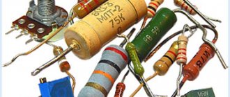
Three surface mount (SMD) resistors of different values soldered onto a PCB
Resistors are elements of electronic equipment and can be used as discrete components or as components of integrated circuits. Discrete resistors are classified by purpose, type of current-voltage characteristic, method of protection and installation method, nature of resistance change, and manufacturing technology.
By purpose:
- general purpose resistors;
- resistors for special purposes: high-resistance (resistance from tens of MOhms to units of TOhms, operating voltages 100-400 V);
- high-voltage (operating voltage - tens of kV);
- high-frequency (have small inductance and capacitance, operating frequencies up to hundreds of MHz);
- precision and ultra-precision (increased accuracy, tolerance 0.001 - 1%).
By the nature of the change in resistance:
| Fixed resistors (for wall-mounted installation). | Variable resistor. | Trimmer resistors. | Precision multi-turn trimmer resistor. |
- fixed resistors;
- variable adjustment resistors;
- variable tuning resistors.
According to the method of protection against moisture:
- unprotected;
- varnished;
- compounded;
- pressed into plastic;
- sealed;
- vacuum
By installation method:
- for printed circuit installation;
- for wall-mounted installation;
- for microcircuits and micromodules.
According to the type of current-voltage characteristic:
- linear resistors;
- nonlinear resistors: varistors - resistance depends on the applied voltage;
- thermistors - resistance depends on temperature;
- photoresistors - resistance depends on illumination;
- strain gauges - resistance depends on the deformation of the resistor;
- magnetoresistors - resistance depends on the strength of the magnetic field.
- memristors (being developed) - the resistance depends on the charge flowing through it (the integral of the current during operation).
By type of conductive elements used:
| Wirewound resistor with tap. | Film carbon resistor (part of the protective coating has been removed to demonstrate the conductive layer). |
- Wirewound resistors. They are wound from wire or tape with high resistivity onto any frame. Usually have significant parasitic inductance. To reduce parasitic inductance, they are almost always made with bifilar winding. High-resistance small-sized wirewound resistors are sometimes made from microwire. Other types of resistors are called non-wire resistors.
- Non-wire resistors. A resistive element is a volumetric structure of a physical body or surface layer formed on insulating parts (a thin film of a metal alloy or composite material with a high resistivity, low thermal resistance coefficient, usually deposited on a cylindrical ceramic core). The ends of the core are equipped with pressed metal caps with wire leads for installation. Sometimes, to increase resistance, a helical groove is made in the film to form a helical configuration of the conductive layer. These are now the most common type of resistors for through-hole mounting on printed circuit boards. Resistors are made using the same principle as part of a hybrid integrated circuit: in the form of metal or composite films deposited on a usually ceramic substrate by vacuum deposition or screen printing.
By type of materials used:
- Carbon resistors. They are produced in film and volumetric forms. Films or resistive bodies are mixtures of graphite with organic or inorganic substances.
- Metal film or metal oxide resistors. A thin metal strip is used as a resistive material.
- Composite resistors.
- Wirewound resistors.
- Integral resistor. A resistive element is a lightly doped semiconductor formed in a microcircuit crystal in the form of a usually zigzag channel, isolated from other circuits of the microcircuit by a pn junction. Such resistors have a large nonlinearity of the current-voltage characteristic. They are mainly used as part of integrated monocrystalline microcircuits, where it is fundamentally impossible to use other types of resistors.
Where is it used (scope of application)
Thermistors are actively used in various fields closely related to electronics. They are especially important when implementing processes that depend on the correct temperature settings.
This approach is relevant for computer technologies, information transmission devices, high-precision industrial equipment, etc.
A common way to use thermistors is to limit the currents that arise during the startup of devices.
When voltage is applied to the power supply, the capacitor quickly gains capacity, which leads to increased current flow. If you do not limit this parameter, there is a high risk of damage (breakdown) to the diode bridge.
To protect an expensive component, a thermistor is used - an element that limits the current in case of sudden heating. After the mode is normalized, the temperature drops to a safe level and the thermistor resistance returns to its original level.
Device and types
A thermistor is a semiconductor element that, depending on its type, changes resistance as the temperature rises/falls. Today there are two types of products:
- Thermistors are negative temperature coefficient (NTC) parts. Their peculiarity is that the resistance drops with increasing temperature.
- PTC resistors are elements that have a “positive” temperature coefficient (PTC). Unlike the previous form, as T increases, the resistance, on the contrary, increases.
Depending on the type of semiconductor, different elements are used in its production. As noted, when creating resistive elements, oxides, chalcogenides and halides of various metals are used, and the design may vary depending on the application.
Classification of thermistors
The dimensions and design of thermistors are different and depend on their area of application.
The shape of thermistors may resemble:
- flat plate;
- disk;
- kernel;
- washer;
- handset;
- bead;
- cylinder.
The smallest thermistors are in the form of beads. Their dimensions are less than 1 millimeter, and the characteristics of the elements are stable. The disadvantage is the impossibility of mutual substitution in electrical circuits.
Classification of thermistors by the number of degrees in Kelvin:
- ultra high temperature - from 900 to 1300;
- high temperature - from 570 to 899;
- medium temperature - from 170 to 510;
- low temperature - up to 170.
Types by operating principle
Thermistors differ in their operating principle. There are two types:
- CONTACT. This category includes thermocouples, temperature sensors, filled thermometers and bimetallic type thermometers.
- CONTACTLESS. This group includes thermistors built on the infrared operating principle. They are actively used in the defense sector due to their ability to detect thermal radiation from infrared and optical rays (emitted by gases and liquids).
Types of thermal resistors with positive TCR
Let's look at the types of thermal resistors; they are the same for PTC and NTC.
Varieties according to action features
Based on the type of action (triggering), there are the following types of TR:
- with the contact principle: thermocouples, sensors, filled and bimetallic thermometer elements;
- contactless. These are thermistors with an infrared principle. Common in the defense industry, they can respond to thermal infrared radiation, optical rays emitted by gases and liquids.
Rating, varieties according to temperature parameters
Details are more often considered in the international SI measurement system, in Kelvin. You need to convert K to degrees Celsius in a special way - by comparing two scales.
One degree K is equal to 1° C, but the points on the scales are different: 273.150 corresponds to zero Celsius on a ruler graduated in Kelvin. There is also such a mark as absolute zero, but this is not “0 ° C” - it is equal to o.
Thermistors vary in their degree of response to a certain temperature as follows:
- low temperature. React to temperatures below −102 °C (in Kelvin 170 ° K);
- average 170…510° K;
- high: from 570° K;
- separate type: 900…1300° K.
The initial characteristics of thermistors - thermistors, posistors - can change when operating with frequent fluctuations in temperature.
Classification by temperature triggering
Thermistors differ in the temperature to which they respond when triggered. From this position, the following types of parts are distinguished:
- LOW TEMPERATURE. Such elements operate at temperatures below 170 Kelvin (minus 1020C). 1 Kelvin = minus 272.150C.
- MEDIUM TEMPERATURE. Here the operating range is higher and lies between 170 and 510 Kelvin.
- HIGH TEMPERATURE. Thermistors of this class operate at temperatures from 570 Kelvin.
- SEPARATE CLASS. An individual group of high-temperature thermal resistors operating in the range from 900 to 1300 K will also be highlighted.
Regardless of the type (posistors, thermistors), thermistors can operate in different temperature conditions and external conditions. When operating under conditions of frequent temperature changes, the initial parameters of the part may change.
We are talking about two parameters - the resistance of the part at room temperature and the resistance coefficient.
Diamond and related materials - special thermistors
There is a special class of devices on the thermistor market - based on diamond single crystals, composites and carbon films. They have several advantages:
- operability at temperatures up to 1000 degrees;
- extremely high resistance to aggressive influences;
- high hardness with low inertia.
Such devices have a special marking - TPA. They are produced without a case or in a glass shell.
By type of heating
Based on the heating method, thermistors are divided into two types:
- DIRECT HEATING. This refers to a change in the temperature of a part under the influence of ambient air or current flowing through the part. Devices with direct heating are most often used to solve two problems - changing the temperature or restoring normal operation. Such thermistors are used in thermometers, chargers, thermostats and other devices.
- INDIRECT HEATING. Unlike the previous type, here heating occurs due to elements located in close proximity to the resistor. The nodes are not interconnected in any way. With this approach, the resistance of the semiconductor is determined by the change in current that passes through nearby elements. Thermistors operating on the indirect principle have found application in multimeters (combined instruments).
Definition
Resistor comes from the English “resistor” and from the Latin “resisto”, which translated into Russian sounds like “I resist”. In Russian-language literature, the word “resistance” is used along with the word “resistor”. From the name, the main task of this element is clear - to resist electric current.
It belongs to the group of passive elements, because as a result of its operation, the current can only decrease, that is, unlike active elements, passive elements themselves cannot amplify the signal. Which of Kirchhoff’s second law and Ohm’s law means that when current flows across a resistor, the voltage drops, the magnitude of which is equal to the value of the flowing current multiplied by the value of the resistance. Below you can see how resistance is indicated in the diagram:
The symbol on the diagram is easy to remember - it is a rectangle, according to GOST 2.728-74 its dimensions are 4x10 mm. There are designation options for resistors of different dissipation powers.
Main parameters of thermistors
When choosing a part, it is important to focus on its indicators and characteristics, which vary depending on the type, manufacturer, source material and other indicators.
When choosing a product, you need to find out the main parameters and determine whether they are suitable for solving the task or not.
Thermistor parameters:
- DIMENSIONS. When purchasing, you need to be sure that the part is the right size and will fit on the board (in the circuit).
- RESISTANCES RT and RT. Parameters are measured in Ohms and are indicated in relation to the current temperature in degrees Celsius or Kelvin. If the part is designed to operate at temperatures from -100 to +200 degrees Celsius, the temperature regime for the environment is assumed to be 20-25 degrees Celsius.
- TIME CONSTANT Τ (SEC). The parameter reflects thermal inertia. The calculation takes into account the time required to change the temperature of the thermal resistor by 63% of the difference in t of the part and the surrounding air. In most cases, this parameter is taken equal to 100 degrees Celsius.
- TCS (% per degree Celsius). As a rule, this indicator is prescribed for the same temperature t as the cold resistance. In such a situation, other numbers are used in the designation - at.
- Dissipation power Pmax (maximum permissible parameter), W. Based on this indicator, one can judge the limit before which no irreversible changes occur in the semiconductor (the parameters remain the same). In this case, the temperature tmax cannot be exceeded when Pmax is reached.
- Temperature tmax is the maximum permissible parameter at which the characteristics of the thermistor remain unchanged for a long time (at the level set by the manufacturer).
- Energy sensitivity coefficient (measured in W/percent*R). Designation - G. The indicator reflects the power that must be dissipated on the part to reduce the R parameter by one percent.
- Dissipation coefficient (measured in Watts per degree Celsius). Symbol - H. The parameter reflects the power that is dissipated by the thermal resistor when the temperature conditions of the part and the surrounding air differ by one degree.
The coefficients discussed above (G and H) depend on the characteristics of the semiconductor used and the characteristics of heat exchange between the product and its environment. The parameters are related to each other through a special formula - G=H/100a.
- Heat capacity (measured in Joules per degree Celsius). Symbol - C. The indicator reflects the amount of heat (energy) required to heat the thermistor by one degree.
Some of the parameters discussed are related to each other. In particular, the time constant τ is equal to the ratio between the heat capacity and the dissipation coefficient.
When purchasing a positron, in addition to the above parameters, you need to take into account the range of positive temperature resistance and the factor of change in R in the positive TCR sector.
Basic characteristics of thermistors
When evaluating thermistors, you need to take into account and analyze their characteristics:
- Current-voltage characteristic is a curve on a graph showing the dependence of the voltage on the sample on the current passing through the thermistor. The graph is drawn taking into account thermal equilibrium with the surrounding nature. The graphs are different for posistors and thermistors.
- Temperature characteristics. When plotting a graph, the dependence of resistance on temperature in a certain mode is removed. On the R axis, the parameter is set according to the principle of tenfold increase (10X), and on the time axis, a section in the range from zero to 223 Kelvin is skipped.
- Heating characteristic. Using the graph you can see the parameters of thermal resistors operating on the indirect principle. In other words, the curve reflects the dependence of the resistance of the part on the power supplied to it. When indicating a graph, the resistance scale is taken taking into account 10X.
Description of the experimental setup
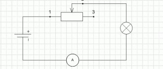
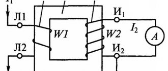
The current-voltage characteristics are measured according to the scheme shown in Fig. 3.
Fig.3. Electrical installation diagram
The measuring circuit is powered by a constant regulated voltage source with a built-in voltmeter. The current through the thermistor is measured with a milliammeter.
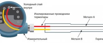
The MMT-4 thermistor is placed in a demonstration tube with terminals, which does not allow hot water to come into contact with the thermistor body; a liquid thermometer (it is advisable to use a mercury thermometer) can be installed in the tube to control the temperature, directly next to the thermistor.
Variable resistor R2 is only needed if an unregulated power supply is used.
General operating principle
Thermistors are made as sensitive as possible to changes in temperature, because they work on this principle. In the absence of heating, the atoms that make up the part are in the correct order and form long rows.
In case of heating, the number of active “charge carriers” increases. The more such units, the higher the conductivity of the material.
When studying the curve of resistance versus temperature, you can see a nonlinear type characteristic. At the same time, the thermistor shows the best characteristics in the range from -90 to +130 degrees.
It is important to take into account that the operating principle of such parts is based on the correlation between the temperature regime and the metals in the part.
The thermistor itself is made using semiconductor compounds (oxides, manganese, copper, nickel, silicates, iron and others). Such components are able to respond to the slightest change in temperature.
The created electric field pushes the electron, which moves until it hits the atom. For this reason, the movement of the electron is slowed down.
As temperature increases, atoms move more actively. Under such circumstances, the original act will collide with another element more quickly. As a result, additional resistance arises.
After the operating temperature decreases, electrons “fall” into lower valence levels and enter an unexcited state. In other words, they move less and do not create as much resistance.
If the temperature rises, the R indicator also increases. But here you need to take into account the type of thermistor, on which the principle of increasing and increasing resistance when the temperature changes depends.
NTC
NTC thermistors are products with a negative temperature coefficient. Their feature is increased sensitivity, high temperature coefficient (one or two orders of magnitude higher than that of metal), small dimensions and a wide temperature range.
NTC semiconductors are easy to use, stable in operation and can withstand heavy overload.
The peculiarity of NTC is that their resistance increases as the temperature decreases. Conversely, if t decreases, the parameter R increases. Semiconductors are used in the manufacture of such parts.
The principle of operation is simple. As the temperature increases, the number of charge carriers increases sharply, and electrons are directed to the conduction band. In the manufacture of parts, in addition to semiconductors, transition metals can also be used.
When analyzing NTC, you need to take beta into account. It is important if the product is used for temperature measurement, for graph averaging and calculations using microcontrollers.
Typically, NTC thermistors are used in the temperature range from 25 to 200 degrees. Therefore, they can be used for measurements within the specified limit.
The scope of their use needs to be considered separately. Such parts are inexpensive and useful for limiting inrush currents when starting electric motors, protecting Li batteries, and reducing the charging currents of the power supply.
The NTC thermistor is also used in a car - a sensor used to determine the cut-off point and turn on the climate control in the car.
Another application is to monitor engine temperature. If the safe limit is exceeded, a command is sent to the relay, and then the engine is turned off.
Dependence of resistance and temperature
The resistance of ideal semiconductors (the number of holes and charge carriers are the same) depending on temperature can be represented by the following formula
R(T) = A exp(b/T)
where A, b are constants depending on the properties of the material and geometric dimensions.
However, the complex composition and non-ideal charge distribution in a thermistor semiconductor does not allow direct use of the theoretical dependence and requires an empirical approach. For NTC thermistors, the Steinhart and Hart approximation is used
It will be interesting➡ How is parallel and series connection of resistors different?
1/T = a+b(lnR)+c(lnR)3
where T is temperature in K;
R – resistance in Ohm;
a,b,c – thermistor constants determined during calibration at three temperature points spaced from each other by at least 10 C.
Glass thermistor.
A typical 10 kOhm thermistor has coefficients in the range of 0-100 C close to the following values:
- a = 1.03 10-3
- b = 2.93 10-4
- c = 1.57 10-7
Disc thermistors can be interchangeable, i.e. all sensors of a certain type will have the same characteristic within the tolerance specified by the manufacturer. The best possible tolerance is generally ±0.05 C over the range 0 to 70 C. Bead thermistors are not interchangeable and require individual calibration.
Thermistors can be calibrated in liquid thermostats. It is necessary to seal the thermistors by immersing them in glass test tubes. Usually, for calibration and calculation of constants, the thermistor is compared with a standard platinum thermometer.
In the range from 0 to 100 C, comparison is carried out at points with an interval of 20 C. The interpolation error usually does not exceed 1–5 mK when using the modified Steinhart and Hart equation:
1/T = a+b(lnR)+c(lnR)2 + d(lnR)3
Reference points can also be used: the triple point of water (0.01 C), the melting point of gallium (29.7646 C), phase transition points of eutectics and organic materials.
To calibrate several thermistors, they can be connected in series so that the same current passes through them. When calibrating and using thermistors, it is important to take into account the heating effect of the measuring current. For a 10 kOhm thermistor, it is recommended to select currents from 10 μA (error 0.1 mK) to 100 μA (error 10 mK).
To begin with, let's define this type of radio components as thermistors (or, as they are also called, thermistors). They are a semiconductor element whose resistance changes depending on temperature. This dependency could be:
- Direct (the higher the temperature, the higher the resistance) is the PTC type (from the English Positive Temperature Coefficient, that is, positive/positive temperature coefficient). An alternative name is “posistors”.
- Reverse (resistance increases as temperature decreases and vice versa) is the NTC type (from the English Negative Temperature Coefficient, that is, negative/negative temperature coefficient).
Thermistors are often divided according to operating temperature ranges:
- Low temperature (below 170 K);
- Medium temperature (170-510 K);
- High temperature (over 510 K).
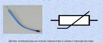
The thermistor designation is shown in the figure below.
Thermistor device.
PTC
Unlike the thermistors discussed above, PTC thermistors have a positive resistance coefficient. This means that if the part heats up, its resistance also increases. Such products were actively used in old televisions equipped with color telescopes.
Today, there are two types of PTC thermistors (depending on the number of pins) - with two and three taps. The difference between three-terminal products is that they contain two positrons, shaped like “tablets”, installed in one housing.
Outwardly it may seem that these elements are identical, but in practice this is not the case. One of the “tablets” is smaller. The resistance also differs - from 1.3 to 3.6 kOhm in the first case, and from 18 to 24 Ohm for the second such tablet.
Two-terminal thermistors are manufactured using semiconductor material (most often Si - silicon). Externally, the product looks like a small plate with two terminals at different ends.
PTC thermistors are used in various fields. Most often they are used to protect power equipment from overload or overheating, as well as to maintain a safe temperature.
Main areas of application:
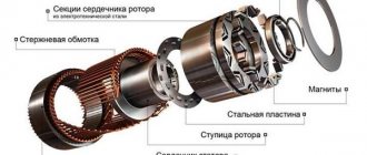
- Protection of electric motors. The purpose of the product is to protect the winding from burnout in the event of a rotor wedge or in the event of a breakdown of the cooling system. The posistor plays the role of a sensor connected to a control device with executing relays, contactors and starters. When a force majeure situation occurs, the resistance increases, and the signal is sent to the control element, which gives the command to turn off the motor.
- Protection of transformer windings from overheating or overload. In such a circuit, a posistor is installed in the primary winding circuit.
- Heating unit in glue guns.
- In cars for heating the intake tract.
- Demagnetization of CRT picture tubes, etc.
Application area
The use of devices depends on their cost and measurement accuracy. More expensive posistors are used in complex industries, and also as fuses. For example, they are connected to an executive relay; in case of heating, the circuit turns off. Thermistors are much more affordable, which allows them to be widely used in everyday life.
Air temperature sensor
When properly calibrated, the NTC resistor can be used to test the heating of the surrounding air. In this case, measurement accuracy, as in production, is not required - adjustment in steps of 1 degree Celsius is sufficient.
Homemade air temperature sensor
Car temperature sensor
A popular method of application is to protect the car engine from overheating. The TP is connected to a relay, which turns off the engine if there is a threat of overheating. With sufficient knowledge, you can connect the device to the on-board computer to display the temperature on the display.
Fire sensor
From a thermistor and bimetallic elements of the starter, you can create a structure similar to a fire alarm. Simple bead TRs are suitable for this. The sensor can also work if it is necessary to exclude triggering by smoke, for example, cigarette smoke.
Thermistor as a starting current regulator
There are a number of appliances that are susceptible to excessive currents when first started: lamps, motors and transformers. To limit them, a thermistor is built into the circuit. Instead of sudden jumps, the current is adjusted according to the load as the thermistor heats up and the resistance decreases.
How to check with a multimeter
An important issue when operating thermistors is knowledge of the principles for testing them. When assessing serviceability, you need to understand that there are two types of thermistors - with positive and negative temperature coefficients (this was mentioned above). Consequently, the resistance of the part decreases or decreases with increasing temperature.
Taking into account this fact, to check the thermistor you only need two elements - a heating soldering iron and a multimeter.
Algorithm of actions:
- Switching the device to resistance measurement mode.
- Connecting the probes to the thermistor terminals (location does not matter).
- Fixing the resistance on paper and bringing the heated soldering iron to the part.
- Resistance control (it rises or falls depending on the type of thermistor).
- If the resistance decreases or increases, the semiconductor is working correctly.
For example, you can use an NTC thermistor type MF 72. In normal mode, it shows a resistance of 6.9 ohms at normal temperature.
After bringing the soldering iron close to the product, the situation changed - the resistance went downward and stopped at two ohms. Based on this check, we can conclude that the thermistor is working properly.
If the resistance changes sharply or does not move at all, we can talk about the failure of the part.
It is worth considering that such a test is very rough. For accurate control, you need to check the temperature and resistance of the thermistor, and then compare the data with the official parameters.
Functionality check
You can check the thyristor either using a multimeter or by creating a simple test circuit. If you have the technical specifications in front of your eyes when making a test, you can at the same time check the resistance of the transitions.
One of the types: power T122-25
Testing with a multimeter
First, let's analyze the continuity test with a multimeter. We switch the device to dialing mode.
Digital multimeters have a continuity mode that allows you to test semiconductor devices
Next, we touch the pairs of terminals one by one with the probes:
- When connecting the probes to the anode and cathode, the device should show a break - “1” or “OL” depending on the multimeter. If other indicators are displayed in at least one direction, the thyristor is broken.
- There should be a slight resistance in one direction between the anode and the control electrode (lead). In the opposite direction there is a break. If there is either a break or slight resistance in both directions, the element is damaged.
Please note that the resistance value varies from series to series - you should not pay special attention to this. If you want to check the resistance of the transitions, look at the technical specifications
Scheme for checking the performance of a thyristor with a multimeter
The figure shows the test diagrams. The figure on the far right is an improved version with a button that is installed between the anode and the control terminal. In order for the multimeter to record the current flowing through the circuit, briefly press the button.
Using a light bulb and a DC source (a battery will also work)
If you don’t have a multimeter, you can test the thyristor using a light bulb and a power source. Even a regular battery or any other constant voltage source will do. But the voltage must be sufficient to light the light bulb. You will also need resistance or a regular piece of wire. A simple circuit is assembled from these elements:
Scheme for testing a thyristor using a light bulb and a power source
- The plus from the power source is supplied to the anode.
- We connect a light bulb to the cathode, and connect its second terminal to the negative of the power source. The light does not light because the thermistor is locked.
- Briefly (using a piece of wire or resistance) connect the anode and the control terminal.
- The light comes on and continues to light even though the jumper is removed. The thermistor remains open.
- If you unscrew the light bulb or turn off the power source, the light bulb will naturally go out.
- If the circuit/power is restored, it will not light up.
Along with the test, this circuit allows you to understand the principle of operation of the thyristor. After all, the picture turns out to be very clear and understandable.
How to connect
The principle of connecting thermistors is simple (using the example of Arduino). This requires a circuit board, a part, and a 10k ohm resistor. Since the product has high resistance, this parameter for conductors does not affect the final result.
One resistance pin is connected to the 5V pin and the other is connected to the thermistor pin.
The second tap of the thermistor must be connected to ground. The center of the two resistors is connected to the “Analog 0” pin.
<
Where is it located on the diagram
The display of the thermistor on the diagram may vary. The product can be easily found by the designations t and t0. Externally, it is reflected as a resistance through which a strip passes diagonally with a “stand” under t0 from below. The main designations are R1, TH1 or RK1.
If in doubt about the scope of application, the thermistor can be heated and its behavior observed. If the resistance changes, this is the required element.
Thermistors are used almost everywhere - in the charger board, in car amplifiers, PC power supplies, in Li-Ion batteries and other devices. It is not difficult to find them on the diagram.
What can be replaced
It is best to replace the thermistor with a similar one, checking the reference book or technical documentation. However, if you have experience and knowledge about the design of a particular device, you can replace the TP with a regular wirewound resistor. You should check:
- conditions for relay operation - time or voltage;
- changing the time to return to operating mode;
- the need to connect several resistors in series at once.
It is important to understand what functions the TR performed. In some cases, replacement will be impractical or impossible.
Thermistors are a necessary element for the functioning of modern electrical engineering. This is an accurate and efficient sensor that allows you to monitor the operation of devices in many areas. It has been used for more than 90 years; it is unlikely that it will be replaced in the near future.