Description
The Sonoff basic version relay switch allows you to control electrical appliances using a mobile phone. This is achieved by connecting the internal Wi-Fi module of the relay to the home router and providing the router with Sonoff access to the global network.
Sonoff Basic is a compact device that can be easily placed:
- Behind the ceiling;
- In a brick niche;
- In the bowl of a chandelier;
- Inside the lamp.
The kit includes 2 protective caps and screws for fastening during installation.
Firmware
I use the espurna firmware designer to control relays using the MQTT protocol, but it is theoretically possible to use any other firmware designer and even create your own in order to leave all the logic in the microcontroller rather than control it from a separate computer. Espurna has ready-made firmware for the Itead Sonoff TH, but it had to be improved a little to add support for optocoupler input. To do this, the optocoupler contact, which is connected to the RX connector (GPIO 3), must be registered as an additional switch. Take the platformio.ini file, in the section to the build_flags element you need to add elements
-DBUTTON3_PIN=3 -DBUTTON3_MODE=»BUTTON_PUSHBUTTON+BUTTON_DEFAULT_HIGH»
We stitch as usual (by air):
pio run -t upload -e itead-sonoff-basic-dht-ota --upload-port IP_ADDR_OF_ITEAD_SONOFF_TH
After this, the MQTT topic ESPURNA_xxxxxx/button/2 publishes “1” when the switch is on and 2/3/4 when it is off (depending on the duration while the switch was on). The current humidity is published on the ESPURNA_xxxxxx/humidity topic, and you can turn the relay on and off by sending 1 or 0 to the ESPURNA_xxxxxx/relay/0/set topic
In all the specified topics, xxxxxx is the last 6 hexadecimal digits of the ESP8266 MAC address.
Types of models
The manufacturer offers a choice of models from the Sonoff World On series. There is a difference between them and it lies in the method of use:
- Sonoff World On (basic version) is suitable for controlling home appliances such as lamp, chandelier, CCTV camera, freezer.
- Sonoff World On RF is the same relay in the basic version, but comes with one control panel. This solution is well suited for controlling gates or raising barriers.
- Sonoff World On TH is equipped with sensors for measuring temperature and humidity, so the gadget is recommended for use in a greenhouse, next to a boiler or air conditioner.
- Sonoff World On Duo, 4CH and 4CH PRO - work with 2 or 4 devices simultaneously. More suitable for industrial applications.
We recommend reading: review and instructions for using the 4-channel version of the Sonoff 4CH Pro relay.
The type of connection to the device and pairing with a mobile phone is generally similar, so the article discusses further interaction with the simplest relay model.
Possible problems
The main disadvantage of the device is mentioned above: for its normal functioning it requires a constant connection to the Internet, since it transmits data and is managed through the Amazon AWS service. Therefore, you need to make sure that stable network access is provided at the location, or experiment with modified firmware.
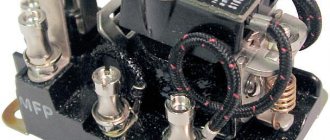
Also, some users reported sudden failure of the switch a month and a half after installation. The 16-amp relay burns out:
Therefore, you should carefully select the connected load and ensure sufficient cooling for the device. But if suddenly something breaks, you don’t have to rush to throw away the device; the manufacturer posts electrical circuit diagrams of its devices on its website.
Having a soldering iron and basic soldering skills will give you the opportunity to breathe a second life into your device.
Other problems include the following:
POW at the final stage of pairing (added, but remains in the “Offline” status in the application) does not connect to the cloud even after a long wait. In this case, you need to turn off and turn on the gadget; When attempting to connect, the green diode repeats a single green flash. This means there is a connection error with the router. Reason: incorrectly entered Wi-Fi password or weak signal
It is also important to remember that Sonoff POW does not support 5 GHz networks, and the router should not limit connections by MAC addresses;
Slow, repeating green flash. It means that the switch is connected to the network and the cloud, but has not been added to the list of devices
You should turn off POW, turn it on and repeat the addition; double repeating blinking - there is a connection with the router, but not with the server. It is necessary to check whether the router has access to an external network; The application cannot connect to the device in pairing state. Most often this happens due to the phone's cache being full. In this case, turning off the smartphone’s Wi-Fi module for about a minute and rebooting the Sonoff gadget helps; When the device is turned on, the diode does not light up. This indicates damage to one of the circuits or board; the gadget should be repaired or replaced.
Specifications
Sonoff Wi-Fi relay has the following characteristics.
| Parameter | Meaning |
| Max current | 10 A |
| Supply voltage | 90–250 V |
| Wi-Fi protocol | 802.11 b/g/n |
| Operating temperatures | 0°C to 40°C |
| Weight | 0.05 kg |
| Dimensions | 88×38×23 mm |
The base of this relay is the Chinese microcontroller ESP8266.
Components of the wireless module
The design of a wireless switch is very simple and consists of two working components: a receiver and a transmitter. Each of these nodes has its own area of responsibility and performs strictly defined functions that ensure correct control of the lighting system.
Design and principle of operation of the receiver
The receiver is a radio-controlled relay, which during operation picks up the corresponding signal and closes the galvanic circuit of household electrical wiring.
The relay is placed as close as possible to the lighting fixture, or somewhere in the neighborhood, but always in a place that falls within the coverage area of the transmitter.
Due to the compactness of the receiving radio relay, it can be placed in a chandelier, sconce or floor lamp. When you want to take control of the control of spotlights, it is appropriate to “hide” the receiver behind the suspended ceiling
Another option is to mount the element into a distribution box, if its dimensions allow this to be done technically. The mini-device is controlled from a remote control, smartphone, tablet, computer via Wi-Fi or radio waves.
Specifics of the transmitter operation
For correct operation, the transmitter does not need to be connected to an active power supply. Power is provided by autonomous energy sources - batteries.
More advanced models have a small internal generator that generates electric current when the user presses a key. The energy pulse that occurs at this time is transformed into a radio signal, which is picked up by the receiving device.
Commands to the module are given from the remote control or via a phone with access to Wi-Fi. In this way it is possible to control up to 8 devices simultaneously
A signal transmitter equipped with an energy generator is more expensive than a similar battery-powered model. But the price is quickly compensated by the ease of use, and the owners do not have to think every time about how not to forget and replace worn-out batteries in a timely manner.
The coverage area of a device depends on many parameters. This is primarily influenced by the general technical characteristics of the product and the structural features of the room (layout, presence of furniture, false walls, etc.) where the module is located.
Simple budget devices transmit the correct signal within a radius of 20-50 meters. In more advanced models, this figure reaches 350 meters, but the price for such powerful devices is still high.
The signal transmitter, operating on rechargeable batteries, does an excellent job of turning on and off the lights in rooms, serves for a long time and requires only one thing from the owners - timely recharging of the batteries using a charger
Some manufacturers produce products with expanded functionality. “Smart” devices take on not only the standard control of turning on/off light bulbs, but also regulate the intensity of lighting devices and the degree of illumination of the room. This mode is ensured by a special component – a dimmer.
The device, equipped with a dimmer, allows you to set the most convenient level of luminous flux saturation. This action is carried out by holding or scrolling the operating button located on the switch itself
The purpose of the dimmer is to regulate the electrical power responsible for the brightness of the light. The device works normally with both LED and traditional incandescent lamps.
Installation and connection
For the relay to work, it needs 220 V power. From this fact it follows that the automation can be disguised anywhere without difficulty. (on the ceiling itself, walled up under a lighting fixture or decoration, in a switch box, in sight for manual control, etc.).
For surface installation it has 2 mounting holes (on the back). The connection diagram is implemented as follows:
- Terminals L and N on the input side (the designation is indicated directly on the front side of the relay) are supplied with phase and zero from a 220 V supply;
- The cross-section of the connected cores must fit within 1.5 square millimeters. Otherwise, there will be problems with attaching the cores to the terminal blocks.
- At the other end of the wire there should be a plug, which in the future will be connected to a 220 V network.
As an example, a power cable of the PVS brand (3 wires - brown, blue, yellow) was used for connection.
Install and tighten using a screwdriver:
- Brown - phase to terminal L.
- Blue - zero to terminal N.
- Leave the yellow one unconnected.
On the reverse side (output) connect the adjustable device in the same way.
After installation, cover the connection area with protective covers. The teeth will allow you to fix the connected wires and protect them from breaking. After installing the cover, tighten it with the mounting screws.
To connect a load of up to 10 A, the relay can be connected according to this scheme.
If the rated current exceeds 10 A, in order not to burn the device, it is recommended to use a contactor in the circuit.
Using the contactor you can control:
- Single-phase and three-phase load;
- Direct and alternating current.
After connecting to the power circuit you can:
- Operate manually;
- Pair your smartphone with the relay and control it via WiFi.
Relay Breadboard Assembly
Schematic diagram of the relay breadboard
To control the relay, I used a BC337 NPN bipolar transistor with a 1 kOhm resistor on the base. To protect against coil reverse voltage I used a 1n4007 diode.
I decided to connect the normally closed (NC) contact of the relay to ground.
Relay Breadboard (Top View)
Relay development board (bottom view)
Wi-Fi connection
To fully control and manage Sonoff from your smartphone, you need to install the Ewelink application. It is available for iPhone and Android devices. The software can be found in the Play Market, App Store and using the QR code on the Sonoff box.
After installing the utility, go to it:
- Complete registration, select a country and email (the gadget must have Internet access).
- Find the verification code on your email inbox and enter it to complete registration.
- After entering your password in two fields, complete registration and log in to your profile.
- Next, in the utility, click the “Add device” button.
- To pair a mobile smartphone and a relay, hold the black button on the Sonoff case for about 5 seconds.
- As soon as the LED flashes green, check the box next to the first option and click next.
- From the list, select your home or office Wi-Fi network and enter its SSID and password (check the box next to “remember data”).
- Wait for the smartphone to detect, connect and configure the connection to the relay.
- After successfully registering your device, you can rename it in the application as you wish.
- Then click the “Finish” button.
Appearance
The Aqara wireless relay is designed in the form of a small, white rectangle with rounded edges. The texture is pleasant to the touch and has a slightly rough, matte surface.
On the front side there are 8 screw fasteners, a pairing button and an activity status indicator:
At the top end there is an external ZigBee antenna, made in the form of a 10 cm wire, and basic information about the device is also duplicated there:
At the bottom end there is a contact group with clarifying inscriptions:
The relay dimensions are 49.3x46x24mm, which can be visually compared to a slightly inflated matchbox
Unfortunately, this is not enough for it to easily fit into a standard, round socket box. Refinement using a file is of course possible, but this is not recommended to avoid undesirable consequences and loss of warranty.
Remote control
If the Sonoff device is online, the green LED on its body lights up statically. When the LED blinks periodically, it indicates that the connection with the router or the Internet has been lost.
To remotely activate or deactivate the load, in the application, click on the relay icon and click on the large virtual power button in the middle.
The timer function is present, so you can configure the control option based on filters:
- Repeat or once;
- Days of the week;
- Date and time;
- Application on the current or next timer.
There is also a second countdown timer. Filters are as follows:
- Enable or disable;
- Enter the day, hours and minutes.
The third (cyclic timer) allows you to set certain cycles (after what time the relay will turn on and after what period of time the relay will change its position). It is also possible to indicate the time and calendar date of the beginning of this cycle.
Set multiple timers with caution. If one time is superimposed on top of the second, then neither the first nor any other programmed timer will perform its intended action.
In the parameters there is an item that allows you to set in what position of the circuit the automation will remain if 220 V suddenly disappears from it:
- Click on the relay icon and click on the three dots.
- Select "Settings".
- Activate the desired label next to “Power to switch”.
When power is applied to the relay, when:
- “On”—the device will turn on.
- “Off” - it will turn off.
- “Stay” will be in the same position as before turning off.
It is recommended to maintain the current version of the application, so in the settings of the utility itself, next to the “Software version” item, the “Download” button may be active.
Xiaomi Aqara Wireless Relay: dual-channel ZigBee relay
Hello, friends
We continue to study the variety of devices for the smart home of the Xiaomi ecosystem, and today we will talk about a rather remarkable device - a two-channel power control relay. Its remarkable feature lies primarily in the fact that it has the ability to be integrated together with a regular, classic switch, making it possible not to give up the usual, independent method of control and at the same time receiving all the benefits of a smart home.
Content
- Where can I buy?
- Supply
- Options
- What is in the box
- Design
- MiHome
- Scheme 1
- Scheme 2
- Home Assistant
- Video version
- Conclusion
Where can I buy?
- Gearbest - price at time of publication $19.99
- Banggood - price at time of publication $32.14
- Aliexpress - price at time of publication $18.99
- JD.ru - price at the time of publication $ 20.83
Ukraine:
- Seanada - price at the time of publication 799 UAH
Russia:
- Rumicom - price at the time of publication 1990 rubles
- Ultratrade - price at the time of publication 1900 rubles
Supply
Everything is traditional for Chinese versions of ZigBee devices. A minimalistic white box with a schematic image of the sensor and an inscription in Chinese. On the back there is the Aqara logo and a list of main technical characteristics. Let's look at them in more detail.
Options
- Management interface - ZigBee
- Maximum load power - 2500 W, but not more than 10 A
- Size – 49.3 * 46 * 24
- Control channels - 2
- External antenna to improve reception quality
What is in the box
Although the box was a little wrinkled on the road, the device itself arrived completely intact and safe.
The kit includes a relay, which is made in the shape of a white rectangle, with eight screw contacts on one side and an external Zigbee antenna on the other side.
In addition to this, the box also contained instructions. It is written only in Chinese, but you cannot put it aside. It has two possible relay connection schemes, which I will talk about next.
Design
On the top side of the relay, there is a pairing button, an activity indicator, a warning sign about the maximum load and 8 screws for the contacts.
At the end of the case there are the 8 contacts themselves and explanatory captions for them. From left to right -
Connection of the zero line, closed contacts L and IN, connection of the incoming phase, two control contacts with a phase for the load and two contacts for connecting a physical switch.
Let me make some remarks - looking ahead, I will say that with both connection schemes, contacts L and IN are closed, the jumper cannot be removed. It seems to me that some more reliable method could be used than an external jumper. Connect them inside the housing without leading a separate wire out. Moreover, for external connection only 1 contact is needed, the second one is already closed with it.
From the opposite end there is an external ZigBee antenna wire coming out, which allows the use of internal installation for the relay. The device parameters are also duplicated.
Dimensions
I mentioned the dimensions in the device parameters, but I think a visual comparison would be better. Personally, from the photo, the relay seemed more massive to me. In fact, it is the same length as a matchbox, but slightly wider and higher. This size, convenient shape and the presence of an external antenna will greatly facilitate the internal installation of the device.
Compared to a standard socket box. Just installing a relay in it won’t work, the dimensions are a little different. But at the same time, as far as I can judge, if internal installation is necessary - then if you remove it from the wall, or drill out the socket box a little in the corners, the relay will fit there normally.
MiHome
To connect the device, you need to connect the zero line to the first connector - N and the phase to the fourth - IN. Next, you can use either my instructions for directly connecting Zigbee devices to the gateway, or using the Mihome connection wizard.
To do this, in the gateway plugin, go to the Device tab at the bottom, click Add Child Device and select a wireless relay from the list that opens.
Next, you need to press the button on the relay for 5 seconds until the LED starts flickering. After a few seconds, the gateway will report a successful connection from the devices. After this, the first setup step will open - selecting a location.
The second step is the name of the device, optionally in Russian, and the third, final step informs that the device has been added to the system. The new device will appear in the list of gateway devices and the general Mihome list
The relay has its own plug-in, which is almost identical to the plug-in of a two-gang switch with a zero line. On the main screen there are control buttons for each channel. There are meters for daily, monthly and current energy consumption. Total consumption for both channels.
By clicking on the counters, windows with graphs open, just like sockets and switches with zero - in terms of day, week and month.
There is one option in the device settings menu - interlock. Despite numerous attempts, I could not activate it - I received a communication error message. I assume that the button is blocked on the relay. There are 6 actions available in the automation menu - each channel can be turned on, off and switched. In the main menu - renaming, changing location, adding a shortcut to the desktop.
Scheme 1
Let's start testing with the first connection scheme, which is simpler and involves the use of only smart home infrastructure. Two loads and a relay are involved.
In real time, all described testing cases can be viewed in the video version of the review!
Pressing the button located on the body causes the relay to switch. If both relays are off, they will turn on
If one relay is on, the other is off, then they will change their status. Switching occurs with a clearly audible click. When controlled from a plugin or through MiHome automation, it works with a small time lag, which depends on the quality of the Internet connection. Separate control for each channel.
When the external power is turned off and restored, the relay turns on in the state in which it turned off, but almost immediately turns off the power if it was turned on.
Scheme 2
The second circuit works with a physical two-button switch. The power and load connections are the same. The input terminal of the switch is connected to the closed relay contacts, and the two outputs are connected to contacts S1 and S2.
With this connection scheme, a physical switch controls both relay channels. At the same time, there is no dependence on the control system or the availability of the Internet. The reaction is immediate.
At the same time, the functionality of the plugin is completely preserved. The control works, energy consumption is calculated, the status is displayed. The operating scheme is completely similar to pass-through switches, only here there is one physical switch, the second is logical.
Home Assistant
As of the date of this review, the relay in the Home Assistant system does not yet work; the system log displays an entry about the need to update the gateway firmware.
Video version
Conclusion
Although at first glance this device is an analogue of a two-key switch with a zero line, but in a different housing, in reality it is a completely different type of gadget. I'm talking about, so to speak, soft integration of a smart home system. When using the second connection scheme, you still have the possibility of purely physical control, without depending on the operation of the control system. But at the same time, the relay allows you to use all, without exception, logical control functions - remote control, energy monitoring, work in automation with any ecosystem infrastructure.
Control from multiple phones
To interact with the relay through several smartphones you can:
- Log in to the Ewelink application from one profile.
- Delegate rights to another profile in the application itself.
To delegate:
- Open the application and expand the connected relay to full page.
- Click the “Share” button and in the new window “Share device”.
- Enter another account and click OK.
Now the relay will be activated on another account and can be controlled. Synchronization of such parameters as: status, timers, settings will work immediately.
Alice
Integration with Alice is quite easy and does not take much time.
Find and install the Yandex-with Alice mobile application on your smartphone. Next, by clicking the icon in the lower right corner, look for the “devices” shortcut on the main screen. By clicking it, we get to the menu where we select the “device management” line. In the new window that appears, click on the icon with (+) located at the bottom and right.
We select the “other device” item and look for “Aqara” there, by clicking we get to the next menu with the only item “merge devices”.
Here we enter your username and password for the Aqara smart home. And after a successful login, click on the “update list of devices” item and after a couple of seconds the same list will appear where our relay will be. Click “next”. That's it, integration with Alice is complete.
Modification
Users note a common problem for Sonoff smart home gadgets - in the absence of the Internet and connection to the Amazon cloud, they become unmanageable. Therefore, some enthusiasts create alternative versions of firmware that allow them to take readings and control the gadget directly, without intermediate servers. The task is made easier by the fact that the switch works on the well-known Chinese ESP8266 controller from Espressif Systems, which is well documented.
The HLW8012 energy metering controller also has developer-accessible specifications, allowing the designer to create their own firmware and interfaces.
Measurement chip pin map:
Here:
- CF - gives power readings;
- CF1 - current and voltage, whose data depends on the readings at the SEL input.
Interesting: on GitHub, developers offer their own versions of libraries for POW.
Program version using the library:
An example of a homemade “counter” web interface created using alternative firmware and the Google Chart service:
Scope of application
Traditional switches are gradually becoming a thing of the past due to inconvenience of use, complexity of connection and installation, as well as a small resource. Wireless analogues have better qualities.
They have a stylish appearance and install within a few minutes.
The use of such products is relevant in the following cases:
- When moving an old switch, when pieces of furniture interfere with its installation. The new device can be mounted anywhere in the room - on a wall, mirror, cabinet or other element of the room.
- To eliminate electrical errors. When installing wiring, mistakes are often made that affect the comfort of living in an apartment or house. In such cases, it is not necessary to make a strobe or plan expensive repairs - you can install a wireless switch (with or without a remote control).
- When there is a shortage of space. The classic option is that it is difficult to install the switch on a cabinet or other piece of furniture due to the complexity of the mounting. Wireless analogues are overhead, and their installation is accessible even to beginners. In addition, during the installation process there is no need to lay the cable and worry about its disguise. And the radio switch can be placed anywhere, be it a coffee table, bar counter, bedside table or other piece of furniture.
- In wooden houses. The advantage of buildings made using wooden materials is undeniable. They are distinguished by their durability, ability to retain heat, and also low price. But when installing wiring, problems arise due to increased safety requirements. The best option is to install open wiring, but it spoils the appearance of the interior and is susceptible to mechanical damage (including from rodents). Making hidden wiring in a wooden house is quite a problem. The best solution is to install wireless light switches, which simplify the process of installing hidden wiring and save money.
- To control lighting from multiple locations. There are situations when turning on the light needs to be done from 2-3 parts of the room. To avoid running wires to each switch, it is better to use wireless devices. With their help, lighting control is simplified and installation time is reduced. If desired, you can install wireless switches with a remote control.
- If necessary, install additional switches. It happens that after completion of the repair work the chosen location is not satisfactory and the installation of an additional device to control the light is required. Installing a wireless switch solves the problem.
- To turn lights on/off over long distances. What to do in a situation where you need to turn the lamp on and off from another room or even from the street? Running a wire to install an additional switch is expensive and unsafe, but new technology allows you to avoid such problems. The peculiarity of radio switches is their large operating range - up to 350 m (depending on the model). Control can be done using a simple remote control, which for convenience is made in the form of a key fob.
- In order to preserve the design of the room. If installing a switch in a recess is not possible, you have to install overhead types of products that spoil the appearance of the room and do not look very solid. The solution to the problem is to install a wireless device that is thin and fits perfectly into the interior.
- As an alternative to conventional devices. During the next renovation of an apartment or house, you want to introduce some innovations into the design and make life more comfortable. One way is to install a wireless remote switch. Such products will cost more, but they are easy to install, have a solid appearance and provide ease of lighting control.