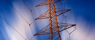
For the transmission and distribution of electrical energy over long areas, overhead power lines (OHLs) located in the open air are used. In terms of voltage, OHL-0.4 kV and OHL-10 kV are widely used; these lines can be seen in rural areas, passing through forest and field areas. What definitely gives them an advantage over alternative electrical installations that transmit electricity is the ability to transmit over long distances. And this is the drawback, the influence on overhead lines of atmospheric precipitation, especially in winter, icing of wires, as well as areas with increased wind characteristics. And yet, overhead lines are used in distribution networks in full.
What is the distance between supports 10 square meters?
For private sector power lines with a voltage of 6–10 kV, intermediate structures of the usual type are used - poles. They are installed at a distance of 60 m. For an anchored reinforced structure, the distance between the supports of a 10 kV power line increases to 250 meters.
Interesting materials:
How to play with a friend online in GTA 5? How to play Minecraft Pirate with a friend online? How to play GTA 5 online on PS3 with a friend? How to play GTA 5 Pirate with a friend? How to play Minecraft with a friend via Hamachi on Pirate? How to play with a friend in Portal 2? How to play with friends through Hamachi? How to play with friends in Battlefield 1? How to play Minecraft with friends from a distance on PC? How to play Saints Row 4 with friends?
Overhead power line
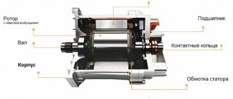
Overhead power line (OTL) is a device designed for transmitting or distributing electrical energy through wires with a protective insulating sheath (OIL) or bare wires (OHL) located in the open air and attached using traverses (brackets), insulators and linear fittings to supports or other engineering structures (bridges, overpasses). The main elements of overhead lines are:
- wires;
- safety cables;
- support supporting wires and hummocks at a certain height above ground or water level;
- insulators that isolate wires from the support body;
- linear fittings.
The linear portals of the distribution devices are taken as the beginning and end of the overhead line. According to their design, overhead lines are divided into single-circuit and multi-circuit, usually 2-circuit.
Typically, an overhead line consists of three phases, so the supports of single-circuit overhead lines with voltages above 1 kV are designed to hang three phase wires (one circuit) (Fig. 1); six wires (two parallel circuits) are suspended on the supports of double-circuit overhead lines. If necessary, one or two lightning protection cables are suspended above the phase wires. From 5 to 12 wires are hung on the overhead line supports of a distribution network with voltages up to 1 kV to supply power to various consumers on one overhead line (external and internal lighting, power supply, household loads). An overhead line with a voltage of up to 1 kV with a solidly grounded neutral is equipped with a neutral wire in addition to the phase ones.
Rice. 1. Fragments of a 220 kV overhead line: a – single-circuit; b – double-chain
Wires of overhead power lines are mainly made of aluminum and its alloys, in some cases of copper and its alloys, and are made of cold-drawn wire with sufficient mechanical strength. However, the most widely used are stranded wires made of two metals with good mechanical characteristics and relatively low cost. Wires of this type include steel-aluminum wires with a ratio of the cross-sectional areas of the aluminum and steel parts from 4.0 to 8.0. Examples of the location of phase wires and lightning protection cables are shown in Fig. 2, and the design parameters of overhead lines of a standard voltage range are given in table. 1.
Rice. 2. Examples of the location of phase wires and lightning protection cables on supports : a – triangular; b – horizontal; c – hexagonal “barrel”; d – reverse “Christmas tree”
Table 1. Design parameters of overhead lines
| Rated voltage of overhead lines, kV | Distance between phase wires, m | length , m | height , m | size , m |
| Less than 1 | 0,5 | 40 – 50 | 8 – 9 | 6 – 7 |
| 6 – 10 | 1,0 | 50 – 80 | 10 | 6 – 7 |
| 35 | 3 | 150 – 200 | 12 | 6 – 7 |
| 110 | 4 – 5 | 170 – 250 | 13 – 14 | 6 – 7 |
| 150 | 5,5 | 200 – 280 | 15 – 16 | 7 – 8 |
| 220 | 7 | 250 – 350 | 25 – 30 | 7 – 8 |
| 330 | 9 | 300 – 400 | 25 – 30 | 7,5 – 8 |
| 500 | 10 – 12 | 350 – 450 | 25 – 30 | 8 |
| 750 | 14 – 16 | 450 – 750 | 30 – 41 | 10 – 12 |
| 1150 | 12 – 19 | — | 33 – 54 | 14,5 – 17,5 |
All of the above options for the arrangement of phase wires on supports are characterized by an asymmetrical arrangement of the wires in relation to each other. Accordingly, this leads to unequal reactance and conductivity of different phases, caused by mutual inductance between the wires of the line and, as a consequence, to asymmetry of phase voltages and voltage drop.
In order to make the capacitance and inductance of all three phases of the circuit the same, transposition of wires is used on the power line, i.e. mutually change their location relative to each other, with each phase wire traveling one third of the way (Fig. 3). One such triple movement is called a transposition cycle.
Rice. 3. Scheme of the full cycle of transposition of overhead power line sections : 1, 2, 3 – phase wires
Transposition of phase wires of overhead power lines with bare wires is used for voltages of 110 kV and higher and for line lengths of 100 km and more. One of the options for installing wires on a transposition support is shown in Fig. 4. It should be noted that the transposition of current-carrying cores is sometimes used in overhead lines; in addition, modern technologies for the design and construction of overhead lines make it possible to technically implement control of line parameters (controlled self-compensating lines and compact overhead lines of ultra-high voltage).
Rice. 4. Transposition support
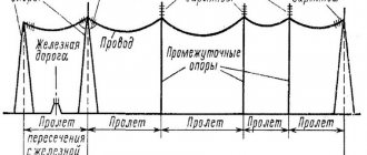
Wires and protective cables of the overhead line in certain places must be rigidly fixed to the tension insulators of the anchor supports (end supports 1 and 7, installed at the beginning and end of the overhead line, as shown in Fig. 5 and tensioned to a given tension. Intermediate supports are installed between the anchor supports , necessary to support wires and cables, using supporting garlands of insulators with supporting clamps, at a given height (supports 2, 3, 6), installed on a straight section of the overhead line; corner (supports 4 and 5), installed at turns of the overhead line route; transitional (supports 2 and 3), installed in the span of an overhead line crossing any natural obstacle or engineering structure, for example, a railway or highway.
Rice. 5. Sketch of overhead power line
The distance between the anchor supports is called the anchor span of the overhead power line (Fig. 6). The horizontal distance between the wire attachment points on adjacent supports is called the span length L. A sketch of the overhead line span is shown in Fig. 7. The span length is chosen mainly for economic reasons, except for transition spans, taking into account both the height of the supports and the sagging of wires and cables, as well as the number of supports and insulators along the entire length of the overhead line.
Rice. 6. Sketch of the overhead line anchor span : 1 – supporting garland of insulators; 2 – tension garland; 3 – intermediate support; 4 – anchor support
The smallest vertical distance from the ground to the wire with its greatest sag is called the line dimension to the ground - h . The line dimensions must be maintained for all rated voltages, taking into account the risk of blocking the air gap between the phase conductors and the highest point of the terrain. It is also necessary to take into account the environmental aspects of the impact of high electromagnetic field strengths on living organisms and plants.
The greatest deviation of the phase wire f p or lightning protection cable f t from the horizontal under the influence of a uniformly distributed load from its own mass, the mass of ice and wind pressure is called the sag arrow. To prevent wires from tangling, the cable sag is 0.5 - 1.5 m less than the wire sag.
Structural elements of overhead lines, such as phase wires, cables, garlands of insulators, have a significant mass, so the forces acting on one support reach hundreds of thousands of Newtons (N). The gravitational forces on the wire from the weight of the wire, the weight of the tension strings of insulators and ice formations are directed normally downward, and the forces caused by wind pressure are directed normally away from the wind flow vector, as shown in Fig. 7.
Rice. 7. Sketch of the span of an overhead power line
In order to reduce the inductive reactance and increase the capacity of long-distance overhead lines, various variants of compact power lines are used, a characteristic feature of which is a reduced distance between phase wires. Compact power lines have a narrower spatial corridor, a lower level of electric field strength at ground level and allow technical implementation of control of line parameters (controlled self-compensating lines and lines with an unconventional configuration of split phases).
From GOELRO to UES
The following classification describes the infrastructure and functionality of overhead power lines.
Based on territory coverage, networks are divided into:
- for ultra-long-distance (voltage over 500 kV), intended for communication of regional energy systems;
- main lines (220, 330 kV), serving for their formation (connecting power plants with distribution facilities);
- distribution (35 - 150 kV), the main purpose of which is to supply electricity to large consumers (industrial facilities, agricultural complexes and large populated areas);
- supply or supply (below 20 kV), providing energy supply to other consumers (urban, industrial and agricultural).
Overhead power lines are important in the formation of the country's Unified Energy System, the foundation of which was laid during the implementation of the GOELRO (State Electrification of Russia) plan of the young Soviet Republic about a century ago to ensure a high level of reliability of energy supply and its fault tolerance.
According to the topological structure and configuration, overhead power lines can be open (radial), closed, with backup (containing two or more sources) power supply.
Based on the number of parallel circuits passing along one route, lines are divided into single-, double- and multi-circuit (a circuit is a complete set of wires in a three-phase network). If the circuits have different nominal voltage values, then such an overhead power line is called combined. Chains can be attached either to one support or to different ones. Naturally, in the first case, the weight, dimensions and complexity of the support increase, but the security zone of the line is reduced, which in densely populated areas sometimes plays a decisive role in drawing up the project.
Additionally, the separation of overhead lines and networks is used, based on the design of the neutrals (isolated, solidly grounded, etc.) and the operating mode (standard, emergency, installation).
Linear fittings
Overhead transmission line fittings include traverses, insulators, clamps and hangers, strips and spacers, fastening devices (brackets, clamps, hardware).
The main function of the traverse is to fasten the wires in such a way as to ensure the required distance between opposite phases. The products are special metal structures made of corners, strips, pins, etc. with a painted or galvanized surface. There are about two dozen standard sizes and types of traverses, weighing from 10 to 50 kg (designated as TM-1...TM22).
Insulators are used for reliable and safe fastening of wires. They are divided into groups, depending on the material of manufacture (porcelain, tempered glass, polymers), functional purpose (support, pass-through, input) and methods of fastening to the traverses (pin, rod and hanging). Insulators are manufactured for a certain voltage, which must be indicated in alphanumeric markings. The main requirements for this type of fittings when installing overhead power lines are mechanical and electrical strength and heat resistance.
To reduce line vibration and prevent wire kinks, special damping devices or damping loops are used.
Maintenance and repair
According to the work regulations, all overhead lines over 1 kV are subject to inspection every six months by maintenance personnel, engineering and technical workers - once a year, for the following faults:
- throwing foreign objects onto the wires;
- breaks or burnout of individual phase wires, violation of the sag adjustment (should not exceed the design values by more than 5%);
- damage or overlap of insulators, garlands, arresters;
- destruction of supports;
- violations in the security zone (storage of foreign objects, presence of oversized equipment, narrowing of the clearing width due to the growth of trees and shrubs).
Extraordinary inspections of the route are carried out during the formation of ice, during river floods, natural and man-made fires, as well as after automatic shutdown. Inspections with lifting onto supports are carried out as needed (at least once every 6 years).
If a violation of the integrity of part of the wire wires is detected (up to 17% of the total cross-section), the damaged area is restored by applying a repair coupling or bandage. In case of major damage, the wire is cut and reconnected with a special clamp.
During the current repair of the air route, rickety supports and struts are straightened, the tightness of all threaded connections is checked, the protective paint layer on metal structures, numbering, signs and posters are restored. Measure the resistance of grounding devices.
Overhaul of overhead power lines involves performing all routine repair work. In addition, a complete re-tensioning of the wires is carried out, with the measurement of the transition resistance of the couplings and post-repair testing.
Preparation and installation
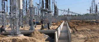
The technological process of constructing an overhead power transmission line consists of preparatory, construction, installation and commissioning work. The first includes the purchase of equipment and materials, reinforced concrete and metal structures, study of the project, route preparation and picketing, development of PPER (electrical installation work plan).
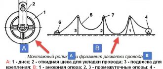
Construction work includes digging pits, installing and assembling supports, distributing reinforcement and grounding kits along the route. The actual installation of overhead power lines begins with rolling out wires and cables and making connections. Then follows lifting them onto the supports, tensioning them, and sighting the sag arrows (the greatest distance between the wire and the straight line connecting the points of its attachment to the supports). Finally, wires and cables are tied to insulators.
In addition to general safety measures, work on overhead power lines requires compliance with the following rules:
- Stop all work when a thunderstorm front approaches.
- Ensuring the protection of personnel from the effects of electrical potentials induced in wires (short-circuiting and grounding).
- Prohibition of work at night (except for the installation of intersections with overpasses, railways), ice, fog, and with wind speeds of more than 15 m/s.
Before commissioning, check the sag and line dimensions, measure the voltage drop in the connectors, and the resistance of the grounding devices.
Secured territory
To ensure the safety, normal functioning, ease of maintenance and repair of overhead power lines, as well as to prevent injuries and deaths, zones with a special regime of use are introduced along the routes.
Thus, the security zone of overhead power lines is a land plot and the air space above it, enclosed between vertical planes located at a certain distance from the outermost wires. The operation of lifting equipment and the construction of buildings and structures are prohibited in protected zones. The minimum distance from the overhead power line is determined by the rated voltage. Dimensions of the protection zone of overhead power lines
| Design voltage, kV | Distance, m |
| up to 1 | 2 |
| from 1 to 20 | 10 (for insulated wires - 5) |
| 35 | 15 |
| 110 | 20 |
| 150; 220 | 25 |
| 330; 500; ±400 (DCV) | 30 |
| 750 (ACV and DCV) | 40 |
| 1150 | 55 |
When crossing non-navigable water bodies, the protective zone of overhead power lines corresponds to similar distances, and for navigable water bodies its size increases to 100 meters. In addition, the guidelines determine the minimum distances for wires from the surface of the earth, industrial and residential buildings, and trees. It is prohibited to lay high-voltage routes over the roofs of buildings (except for industrial ones, in special cases), over the territories of children's institutions, stadiums, cultural, entertainment and shopping areas.
Classification of power lines
is based on a number of characteristics, the first of which is the type of current. They are distinguished: direct current lines (used to a limited extent, since direct current power transmission is mainly associated with the technical difficulties of creating effective inexpensive devices for converting alternating current into direct current at the beginning of the line, and direct current into alternating current at the end of the line) , three-phase alternating current (in terms of the length of overhead lines they are most widespread in the world), multiphase alternating current power lines (six- and twelve-phase) are not widely used. One of the main characteristics of a power transmission line is its throughput, i.e. the greatest power that can be transmitted along a power line, taking into account limiting factors. The power transmitted along three-phase alternating current power lines is related to its length, voltage and current load. According to the rated voltage, power lines are divided into low-voltage (up to 1 kV) and high-voltage (over 1 kV), among which there are medium (3–35 kV), high (110–220 kV), ultra-high (330–750 kV) and ultra-high ( over 1000 kV) voltages. The development of higher voltage levels is due to the need to transmit increasing flows of electricity over increasing distances and the desire to reduce losses from heating of overhead line wires, which are proportional to the square of the current (for example, the current will increase by 2 times, losses will increase by 4 times). According to the number of parallel circuits laid along a common route, overhead lines can be single-circuit (alternating current overhead lines having one set, i.e., three phase wires), double-circuit (overhead lines with two sets of phase wires) and multi-circuit (overhead lines having more than two sets of phase wires). wires). According to their topological characteristics, they distinguish between radial (power comes from a single source), main (several branches extend out) and branches (lines connected at one end to another power line at its intermediate point). According to the functional purpose of power lines, there are distribution lines (lines of local electrical networks), supply lines (lines of regional networks that provide power supply to power centers of distribution networks), as well as system-forming and intersystem, which directly connect different power systems and are intended for mutual exchange of power as in normal and emergency mode.