Section is an image of a figure obtained by mentally dissecting an object with one or more planes. The section shows only what is obtained directly in the cutting plane.
Sections that are not part of the section are divided into extended (Fig. 19, 20) and superimposed (Fig. 21).
It is better to use offset sections. They can be placed in the gap between parts of the same type (Fig. 20).
The contour of the extended section, as well as the section included in the section, is depicted by solid main lines, the contour of the superimposed section - by solid thin lines. The contour of the image of the object at the location of the superimposed section is not interrupted (Fig. 21).
The axis of symmetry of the extended (along the trace of the cutting plane or in the gap) or superimposed section (Fig. 19, 21) is drawn with a dash-dotted thin line without letters and arrows, and the section line is not drawn.
If the extended section (symmetrical or asymmetrical) is made in a free space of the drawing, an open line is used for the section line, indicating the direction of view with arrows and denoted by the same capital letters of the Russian alphabet. The cross-sectional image is designated as “A - A” (Fig. 22).
For asymmetrical sections located in a gap (Fig. 23) or superimposed (Fig. 24), the section line is drawn with arrows, but not marked with letters.
What does cross section mean?
Before revealing the basic concept, you need to decipher the meaning of the term and understand how a wire differs from a cable. A wire is a conductor that is used to connect several sections of an electrical circuit. May have one or many current-conducting conductor elements. They, in turn, can be bare, insulated, single-core or multi-core.
Conductor cut area
The former are used in overhead electrical transmission lines. The latter are used in electrical devices, panels or cabinets. In everyday life, they are located inside electrical wiring.
For your information! Insulated and single-core conductors are used everywhere, and stranded conductors are used where bends with a small radius are needed.
What is a cross section
A cross section is a figure that is formed from a conductive section by a directional plane. The area obtained from a perpendicular cut of any type of wire is indicated in square millimeters. This is an important parameter for calculating the electrical network.
Image performance standard
The execution of schematic images, their sections, various types of sections, cones, beams, and their application to drawings are regulated by various standards. The main one is the Unified System of Design Documentation (USKD) “Images - views, sections, sections.”
This GOST was introduced on January 1, 1968. He stipulates that the image is considered as a projection of an object onto a plane at a certain angle. GOST “Images - views, sections, sections” says that there should be a minimum number of such drawings. But thanks to them, the specialist must obtain complete information about the object.
Therefore, according to their content, GOST divides all images into types, sections and sections. This document also establishes the types of designations, inscriptions and signs.
GOST 2.305-08 regulates that all images must be applied to the drawing using orthogonal (rectangular) projection technology. Ideally, the object is located midway between the observer and the design plane.
But due to the fact that some nodes and elements require consideration from a different angle, this condition is violated. Therefore, the types of sections, drawings of which are used in production conditions, are called images. To implement them, the standards regulate a number of simplifications and abbreviations.
Scope of application
The cross section in the drawing is shown in the form of a figure, which is formed by dividing the part by a plane. Used in electrical engineering, electricity, when a conductor core is considered at right angles to its longitudinal half. Electrons pass through the divided core.
Note! The diameter of the core is not a cross-section. To determine the area of the core, you need to use a special formula for determining a circle.
Knowing the size of the wire cut, length and resistivity, you can find out what resistance the conductor has to the electric current passing through its structure. If you choose the wrong conductor cut, this can lead to a fire in the electrical wiring in the system as a result of its overheating and melting.
You may be interested in this Features of the capacitor
Construction is the main area of application for wires
The purpose of calculating the cross-sectional area may be to obtain the required amount of electricity for the normal operation of electrical appliances, to avoid overpayments with unused energy carriers, to connect powerful equipment to the mains voltage, to prevent a fire in the area, to avoid melting of the insulation layer, to prevent short circuits in household and industrial networks. It could also be getting the lighting system organized correctly.
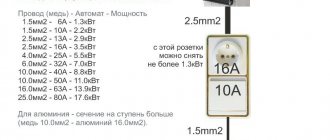
For your information! The normal conductor cross-section for lighting is 1.5 mm² for the line and 4-6 mm² for the input.
Selection by table
Knowing the diameter of the wire, you can determine its cross-section using a ready-made dependence table. The table for calculating the cable cross-section by core diameter looks like this:
| Conductor diameter, mm | Conductor cross-section, mm2 |
| 0.8 | 0.5 |
| 1 | 0.75 |
| 1.1 | 1 |
| 1.2 | 1.2 |
| 1.4 | 1.5 |
| 1.6 | 2 |
| 1.8 | 2.5 |
| 2 | 3 |
| 2.3 | 4 |
| 2.5 | 5 |
| 2.8 | 6 |
| 3.2 | 8 |
| 3.6 | 10 |
| 4.5 | 16 |
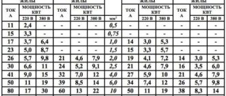
When the cross-section is known, it is possible to determine the permissible power and current values for copper or aluminum wire. In this way, it will be possible to find out what load parameters the current-carrying core is designed for. To do this, you will need a table of the dependence of the cross section on the maximum current and power.
| In the air (trays, boxes, voids, channels) | Section, sq. mm | In the ground | |||||||||
| Copper conductors | Aluminum conductors | Copper conductors | Aluminum conductors | ||||||||
| Current. A | power, kWt | Tone. A | power, kWt | Current, A | power, kWt | Current. A | Power, kWt | ||||
| 220 (V) | 380(V) | 220(V) | 380(V) | 220(V) | 380(V) | 220(V) | |||||
| 19 | 4.1 | 17.5 | 1,5 | 77 | 5.9 | 17.7 | |||||
| 35 | 5.5 | 16.4 | 19 | 4.1 | 17.5 | 7,5 | 38 | 8.3 | 75 | 79 | 6.3 |
| 35 | 7.7 | 73 | 77 | 5.9 | 17.7 | 4 | 49 | 10.7 | 33.S | 38 | 8.4 |
| *2 | 9.7 | 77.6 | 37 | 7 | 71 | 6 | 60 | 13.3 | 39.5 | 46 | 10.1 |
| 55 | 17.1 | 36.7 | 47 | 9.7 | 77.6 | 10 | 90 | 19.8 | S9.7 | 70 | 15.4 |
| 75 | 16.5 | 49.3 | 60 | 13.7 | 39.5 | 16 | 115 | 753 | 75.7 | 90 | 19,8 |
| 95 | 70,9 | 67.5 | 75 | 16.5 | 49.3 | 75 | 150 | 33 | 98.7 | 115 | 75.3 |
| 170 | 76.4 | 78.9 | 90 | 19.8 | 59.7 | 35 | 180 | 39.6 | 118.5 | 140 | 30.8 |
| 145 | 31.9 | 95.4 | 110 | 74.7 | 77.4 | 50 | 775 | 493 | 148 | 175 | 38.5 |
| ISO | 39.6 | 118.4 | 140 | 30.8 | 97.1 | 70 | 775 | 60.5 | 181 | 710 | 46.7 |
| 770 | 48.4 | 144.8 | 170 | 37.4 | 111.9 | 95 | 310 | 77.6 | 717.7 | 755 | 56.1 |
| 760 | 57,7 | 171.1 | 700 | 44 | 131,6 | 170 | 385 | 84.7 | 753.4 | 795 | 6S |
| 305 | 67.1 | 700.7 | 735 | 51.7 | 154.6 | 150 | 435 | 95.7 | 786.3 | 335 | 73.7 |
| 350 | 77 | 730.3 | 770 | 59.4 | 177.7 | 185 | 500 | 110 | 379 | 385 | 84.7 |
Converting watts to kilowatts
In order to correctly use the table of wire cross-section versus power, it is important to correctly convert watts to kilowatts.
1 kilowatt = 1000 watts. Accordingly, to obtain the value in kilowatts, the power in watts must be divided by 1000. For example, 4300 W = 4.3 kW.
How can you do cross-section calculations?
Sometimes you have to measure the cross-section yourself because the wire is not marked. This is not a reason not to use it. First you need to find out what material the core was made of. There is white aluminum, red copper and yellow brass. After this, you need to calculate the area. To do this, you need to find out the conductor diameter by removing the insulation. The diameter can be measured using:
- caliper, micrometer;
- pencil and ruler.
Important! In the second case, the result will be approximate. It should be used in extreme cases. It is better to calculate the diameter using the formula and calipers.
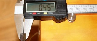
Calipers
You can use a caliper to measure a wire of any size. To do this, you need to place it between calipers. Make sure that they are looking at the scale division. Then calculate the value.
Calipers
Whole numbers can be obtained on the upper scale, and decimals on the lower scale.
Pencil + ruler
If you don’t have a caliper, and the length of the exposed conductor allows you to wrap it around a pencil no less than 1 cm long, you can use this method. All you need is to count the turns that fit on a piece of length 1 cm. The diameter is obtained by dividing the length of the segment into turns.
Using a pencil and ruler, measurements will not be entirely accurate.
Note! The accuracy of the measurement will depend on how tightly the winding was made and how long it is.
General information about cable and wire
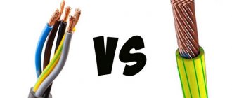
When working with conductors, it is necessary to understand their designation. There are wires and cables that differ from each other in their internal structure and technical characteristics. However, many people often confuse these concepts.
A wire is a conductor that has in its design one wire or a group of wires woven together and a thin common insulating layer. A cable is a core or a group of cores that has both its own insulation and a common insulating layer (sheath).
Each type of conductor will have its own methods for determining cross sections, which are almost similar.
Conductor materials
The amount of energy that a conductor transmits depends on a number of factors, the main one of which is the material of the current-carrying conductors. The following non-ferrous metals can be used as the core material of wires and cables:
- Aluminum. Cheap and lightweight conductors, which is their advantage. They are characterized by such negative qualities as low electrical conductivity, a tendency to mechanical damage, high transient electrical resistance of oxidized surfaces;
- Copper. The most popular conductors, which have a high cost compared to other options. However, they are characterized by low electrical and transition resistance at the contacts, fairly high elasticity and strength, and ease of soldering and welding;
- Aluminum copper. Cable products with aluminum cores coated with copper. They are characterized by slightly lower electrical conductivity than their copper counterparts. They are also characterized by lightness, average resistance and relative cheapness.
Various types of cables according to core material
Important! Some methods for determining the cross-section of cables and wires will depend specifically on the material of their conductor component, which directly affects the throughput power and current strength (method of determining the cross-section of conductors by power and current).
What is the cross section measured in?
After determining the diameter using the indicated methods, the cross-sectional area can be determined using a formula or a special table. It is measured in square millimeters. This unit of measurement is derived according to the Unified International System of Measurements.
You may be interested in this Features of semiconductors
Unit of measurement
At the same time, the cut of the vein was always round.
Formula for measuring cross-sectional area
The cross section, namely the area, can be calculated through the circle formula S = π * R2, where the first link is the area of the circle, the second is the constant Pi 3.14, and the third is the radius. Taking into account the fact that the radius is one half of the diameter, the formula can be rearranged as desired. When calculating area, you should use diameter.
Note! To determine the cross-section of a stranded wire, you need to calculate the area of one core, and then multiply the resulting value by the number of conductor cores.
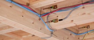
When determining the conductor diameter of indoor electrical wiring, you need to take into account the simultaneous maximum consumer load. Taking into account the power indicator, the cross-section of the lines running from the center of the meter and the input circuit breakers to the distribution box is taken. These are places with the total load of all connected consumers. It is better to make a choice in favor of copper wire with conductors of at least 6 mm².
Formula for calculation
The cross section is the area cut at an angle of 90° to the axis. You can calculate it on the conductor with a caliper, pencil, or ruler. It is measured in square millimeters. It is calculated using the special formula presented above. There is nothing complicated about this, the main thing is to choose the most accurate option.
Number of cutting planes
For simple parts, it is enough to use just one section plane. This is enough to understand how a technician should make this part. But for complex workpieces this is not enough. For example, there are types of beam sections that need to be mentally cut in a more complex way.
For this purpose, standards regulate the use of several cutting planes. They can be broken or stepped. The orientation of the planes plays an important role in this matter.
The angle at which they relate to each other determines the name. If the planes, connecting, form a right angle, this is a stepped cut. When this relationship is characterized by a different slope, the section is broken.
For complex cuts, strokes are drawn at the intersections of the planes. On the final and initial ones, arrows are indicated in the direction of view of the observer. They are located 2-3 mm from the stroke. Letters are placed near the arrows at the intersection points from the position of the outer corner. The cut itself in this case is always marked as “A-A”.