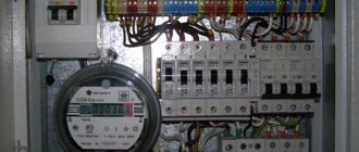
In the process of major renovation of premises or construction of industrial, administrative and residential facilities, new electrical wiring is laid. In distribution boards, circuit breakers are installed on the lines of individual high-power devices, groups of sockets and lighting. The power of the machines and the cross-section of the wires depend on the magnitude of the expected load currents during the operation of each group or individual line. Since several groups or individual lines can be powered from one phase, the machines are connected into one line at the input. The reliable functioning of the entire power supply system of a building, premises or a separate group of consumers in the control panel depends on the high-quality connection of a group of circuit breakers.
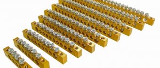
Varieties of combs
There is no universal connecting bus suitable for any circuit breaker. The machines have different dimensions, number of pins and other characteristics. Therefore, combs come in a wide variety.
Based on the shape of the contacts, there are 2 types of comb busbars:
- Pin (toothed). Universal contact suitable for any machine.
- Forked. Used where the tire needs to be clamped under screws.
The combs differ in length, that is, in the number of machines that can be connected to them. If necessary, a tire that is too long can be shortened with a hacksaw. But it is preferable to use products for a standard number of machines:
- 12;
- 24;
- 36;
- 48.
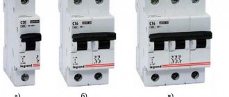
There are also differences in the number of connected phases. From this point of view, connecting busbars are of the following types:
- Per 1 pole (1P). Used to connect single-phase group circuit breakers.
- 2 poles (2P). RCDs, automatic circuit breakers and any other devices that require a phase and zero connection.
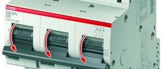
- 3 poles (3P). Used to connect three-phase group circuit breakers.
- 4 poles (4P+N). Three-phase machines and devices that require a neutral wire to operate (three-phase RCDs).
Pin connection bus for three-phase network
Important! If you had to cut one large tire into several small ones, then you need to pay attention to the resulting cut. Individual conductors must not be bent or shorted together. After cutting, you need to remove copper dust from the comb.
Criteria for choosing the method of connecting circuit breakers
First of all, they proceed from the design documentation, determine what characteristics of the circuit, how many machines are planned to be installed in the control panel at each phase, and the electrical parameters of these machines.
At industrial facilities, where many circuit breakers are connected to one phase in distribution boards on one DIN rail. Especially when disconnections are carried out from three phases to different groups of electricity consumers. It is rational to install factory-made connecting busbars; this will significantly reduce the large amount of work, increase the reliability of connections and the stability of operation of industrial electrical installations.
On distribution boards in residential premises there are automatic machines connected to powerful electrical appliances, a heating boiler, electric stoves, split systems, for floor heating. It is also recommended to install factory connecting busbars.
For lighting and socket groups, where power consumption is significantly less, jumpers can be installed with stranded or single copper wire of the appropriate cross-section. When installing connecting jumpers, special attention must be paid to the cross-section of busbars and wires in individual areas.
Design
The combs have a prefabricated design. The structure is based on a flat copper busbar. It has bends for installation on machines. Depending on the number of connected phases, there are 1 or 4 buses in one comb. They are insulated with non-flammable plastic. Usually white or gray.
The design is made in such a way that when assembled there are practically no exposed conductive parts. This increases the safety of operating personnel. And the junction box becomes less susceptible to dust.
Form of conclusions
The most common are comb buses with pin taps (pin type combs). The English name is pin. They fit most modern circuit breakers. The terminals of such tires are more difficult to bend during transportation. Therefore, during installation there are fewer problems with installing circuit breakers into the holes.
The second type of bends is fork-shaped (fork type). They are used relatively less frequently. Not suitable for all types of modern equipment. Connecting bars with forked terminals are not recommended for use with powerful loads. Usually they are placed in a panel with a maximum current of up to 63 A.
Double-pole fork-shaped comb
FAQ
- What combs are best placed on switches if there are connectors for pin structures and FORK plugs?
Both design options provide reliable contact; some believe that the connection area of the fork contacts is larger than the pin contacts. Such comparisons are not noted in the technical parameters.
- How to determine the cross-section of the bus contacts in order to find out the permissible voltage and load currents?
These parameters are indicated in the product passport upon purchase and are marked with markings on the body and embossing on the copper busbar.
Install the busbars in accordance with the maximum current parameters of the machine in the row.
- Installation of a solid state relay (installation diagram)
- Connecting the overcurrent relay
- How to choose a circuit breaker by power, current, pole
- How to check your electricity meter readings
- Installing a power limiter (diagram)
Pros and cons of connecting busbars
Comb connectors are replacing classic wire jumpers from the practice of electricians. This is explained by the advantages that they have in comparison with outdated installation methods:
- Connecting machines is an order of magnitude faster. It is much easier to insert and tighten the comb than to sit and cut the jumpers by hand.
- More reliable contact. By increasing the contact area between the terminal block of the machine and the comb output.
- Double reduction in the number of contacts inserted into the machine. Instead of 2 wires from the jumpers, you need to insert 1 pin from the comb. This factor increases the reliability of the junction box.
There are also disadvantages:
- When repairing the contact connections of the machine, it is necessary to remove the entire comb. Otherwise, the switch will not be able to be pulled off the DIN rail.
- To install additional circuit breakers, you will need to purchase a new longer busbar. Therefore, it is better not to use the comb on temporary equipment or to immediately install additional modular devices for the future.
- Price. Old jumper wires are practically free. They can be made even from scraps of wires lying around under your feet. You will have to buy a comb tire in a store.
Connecting machines with wires is cheaper
Additional Information. The comb requires periodic inspection and maintenance. It is important to pay attention to the temperature and color of the connector and, if necessary, tighten the screws of the circuit breakers.
Connecting circuit breakers in the control panel using wire jumpers
Connecting switches with wires is a more labor-intensive but cheaper process; there are two effective ways to install jumpers:
- Wires of the appropriate cross-section are cut into pieces of sufficient length to connect two adjacent machines. The insulation from the ends of the segments is removed by 8 - 10 mm, this is quite enough to ensure reliable contact; the exposed part of the wire should not protrude beyond the circuit breaker body.
- The second method, when the conductor is not cut into pieces, insulation is removed at the connection points, 1.5 - 2 cm is folded in half. In this form, the stripped area is inserted into the terminal hole and clamped with a screw.
Jumpers can be made with multi-core flexible and rigid single wires.
Tip No. 2 There are specialized tips for crimping the ends of multi-core jumpers, which are easily crimped with special pliers; in extreme cases, you can clamp them with pliers.
Connecting machines via a comb
When using a comb bus, circuit breakers are connected in a parallel connection. If the comb is designed for 1 pole, then 1 phase is suitable for each machine. Such a connector is usually called a phase connector. It is located at the top of the line of switches. There is 1 common incoming wire to the comb. She multiplies it into separate group machines.
If the bus is two-phase, then the machines receive a phase and a zero. In this case, two-pole protection devices are required.
Installation rules
When installing connectors, you must follow the electrical regulations applicable to such devices. This increases the safety and reliability of electrical equipment. The basic installation principles are:
- Before installing the comb, it is necessary to ensure the mechanical integrity of the interphase insulation. Test the terminals with a multimeter for short circuit. This will reduce the risk of phase-to-phase faulting.
- The plastic protruding part of the comb bus should be located on the lever side of the machine and completely cover the conductive parts. The comb is installed so that the copper leads are inaccessible for touching by service personnel.
- Some models of circuit breakers have 2 types of terminal blocks. Some are designed for connecting pin combs, others for fork combs. Before installation, you need to find out what exactly you are dealing with.
- Fork combs are used at currents up to 63 A. Overloading the product will lead to heating, melting of the insulation and phase-to-phase short circuit.
Connecting single-phase devices
Single-phase connection is the simplest. It is used for single-pole machines. The procedure is as follows:
- All protection devices are installed in a row. This requires a DIN rail.
- For each individual device, the screws in the terminal blocks are loosened to a certain point. This is done from the top side.
- One single-pole bus is inserted into the terminal blocks of circuit breakers. The pitch of its teeth should be 17.5 mm.
- The screws are tightened. The tightening is tight enough to securely fix the tire pins.
Connecting RCDs and differential circuit breakers
To connect single-phase RCDs and differential circuit breakers, you will need a double-row comb bus. It must be installed at the top of the protective devices. One bus is considered phase. Its pins should be connected to the L terminals of the RCD. The second bus is zero. Connects to N pins.
When assembled, the line will alternate between phase and zero. And the distance between the individual pins of one bus will be twice the width of a conventional circuit breaker, that is, 35 mm.
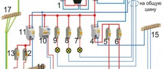
Basic connection diagrams for circuit breakers in distribution boards
This diagram shows the connection of machines in a single-phase network; circuit breakers 4-7-8-9-10-11 are logically connected with a single-pole bus.
| Name | Price |
| Comb bus 1-phase 63A (1m) | 600 rub. |
| PIN bus 3-phase 63A (1m) | 1600 rub. |
| Copper busbar 3-phase 100A (1m) | 1400 rub. |
One of the disadvantages of a bus connection is the high price; it must be borne in mind that the reliability of the connections ensures long-term trouble-free operation, which completely pays for this cost.
In this scheme, it is recommended to place the RCD and circuit breakers on the same DIN rail and connect it at the input with a four-pole bus.
Connecting three-phase circuit breakers and RCDs
With three-phase protection devices you will need a 3 or 4 pole comb busbar. A four-pole comb is necessary when, in addition to 3 phases, a neutral wire is also used.
Assembling the chain is carried out similarly to the previous method. The bus is located on top of the RCD or differential circuit breaker. The comb to which the L1 wire is connected must supply voltage to all L1 terminals of the protective devices. For L2, L3 and N - the same. In this case, L1, L2, L3 and N should not be connected to each other. After installation, it is necessary to turn off all machines and make sure that there is no such short circuit.
CS-CS.Net: Laboratory of the Electroshaman
ABB circuit breakers of the S200 and SH200L series and signal contacts for them
I have the urge to post on the blog again. This post has been requested for a long time, because I again have to explain to many clients, and at the same time to many people on forums, how to connect machines to each other, how to supply power, and whether it is possible to cram three or five wires into one machine. At the same time, I mention some special tricks of ABB machines and send everyone to read their catalog and look at pictures.
So today there will be no catalogs! And there won't even be any pictures. There will be PHOTOS! I apologize in advance: some of them were not as clear as I would like, but they convey the meaning of the actions.
So today we're looking at three things. Features of the clamps for the wires of ABB automatic machines of the S200 and SH200L series, special bus combs for powering the automatic machines in a bunch, and as a bonus - cunning additional signal contacts, which can sometimes come in handy. Let's go explore!
ABB S200 and SH200L series of automatic machines: Clamps and connection
I declare to everyone here and everywhere that I ONLY work with S200 , and DO NOT work with the SH200L . Now I will explain what this is connected with. Firstly, no matter how funny it may seem, the S200 series is the least counterfeited because it is more expensive. This is connected with all sorts of retail outlets in the markets, which are purchased from who knows where. I have personally seen some really cool ones that say SH20x (without L) and have a breaking capacity of 6 kA. However, according to the ABB catalog there are only two options:
- S200 (S201, S202, ... - according to the number of poles of the machine) with a breaking capacity of 6 kA
- SH200L (SH201L, SH202L, ... - according to the number of poles of the machine) with a breaking capacity of 4.5 kA
It’s funny that several comrades from Ukraine wrote to me that they have such SH200 - a common thing, and they are even in the local ABB catalogue. What kind of feature this is, I couldn’t find out. For Moscow, SH200 are definitely fake and obscurity.
Cheap series of machines are counterfeited because the buyer on the market (where they are sold) is not sophisticated enough and for him there is a “16A machine”, and it is not explained to him that this one, which is more expensive, is better. He takes whatever is cheaper, and therefore it is not profitable to trade expensive machines in the markets.
Secondly, I use category “B” machines , which are only available in the S200 . This is due to their greater sensitivity and increased reliability of protection. They are guaranteed to work on weak risers in old houses with gas or dilapidated wiring.
Thirdly, there is another very convenient difference, because of which I began to refuse to reduce the cost of shield assemblies. Earlier I said this: “Well, the shield turned out to have such and such components. It can be assembled a little cheaper if you use SH200L . For an apartment this is not so important, and you can slightly reduce the amount of materials.” Now I don’t make such concessions, and here’s why.
The S200 series machines have very convenient clamps for connecting wires! Look closely at the photo below and you will see the difference:
Difference in clamps for S200 and SH200L series
On the left is an S200 . On the right is SH200L . S200 series has a double clamp consisting of a special screw that lowers the pressure plate (in the form of a circle). Below there is a second hole. By default it is intended for connecting special bus wiring (comb). And normally it can be used to connect the second wire to one machine. Below I will show you what it looks like.
The clamp is made in such a way that the wire does not disappear from it anywhere, it does not “spread” around the machine, even if it is some kind of multi-core SIP. The clamp screw has an incredibly strong and convenient slot, which allowed me to safely assemble the panels with a screwdriver without fear of damaging the equipment (I use a good PH2 bit and a Makita screwdriver set to 10-12 force).
Another feature of the S200 is that it is at the same level as other System Pro M Compact (I remind you of the large post about the module review). In the very right edge there is a SH201L, the clamp of which is out of alignment, and everything else is compatible:
All clamps in the System Pro M Compact series have the same appearance
So, I often get asked questions (or I see Kulibin solutions in the forums) like “Make me one machine for all sockets! I’ll connect three (five) cables into it and that’s enough, but we’ll save space in the panel.” Logically, this may well be true, because ordinary sockets in rooms (rooms such as bedrooms, children's rooms) do not have a large load: it is known that the idea of proper electrics is not to turn on kilowatts of heaters, but to get rid of vines of extension cords so that the sockets are nearby, at hand , in all the necessary places.
But physically, unfortunately, no. There is a clear, immutable rule: one clamp = one wire (cable core) . And it should not be violated due to the fact that it is unknown how the clamping pressure will be distributed over several wires: equally, or some wire will be pressed weaker than others. Then it will heat up, the connection will deteriorate, and the clamp of the machine will melt from the heat. Or maybe the whole shield will burn out, like it happened in Irkutsk.
And... in the case of ABB S200 series automatic machines, we can BOLDLY break this rule! After all, do you remember that we have two separate “holes” for two wires? Great! We push two wires there. For the next photo, I took a NYM 5x6 stub and crimped it with an NShVI PV-3 1x10 tip:
Using the S200 series clamp for a standard connection of two wires
It is difficult for the NShVI to fit into the bottom hole for the combs. And it would be even more correct to push it the other way around: the thinner core from the NYM down, and the tip up. But we portray brutal electricians who supposedly don’t know what they’re doing. And we are succeeding!
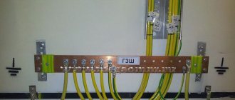
What does this feature do? Firstly, it allowed me to get rid of a ton of zero busbars for each RCD in my shields. Look, for example, at this shield (from this post about shield assemblies):
Another shield for another order, markings from GraphoPlast
Here there is only one breaker on the RCD, because under all the other RCDs (except one) there are two machines. This means that their zeros (two pieces per RCD) can be safely placed under this RCD and stuffed using the standard capabilities. That's why I like working with ABB =)
And secondly, all these clamps are so brutal that they are resistant even to emergency situations. This is when a drunk country electrician uses a crooked screwdriver to try to screw a bent and equally crooked piece of introductory aluminum into the machine. ABB S200 will survive everything =)
We make work easier: Group connection of machines - Bus wiring (combs)
Actually, I once already mentioned that I actively began to use special PS2/58 for a more competent and beautiful connection of a bunch of RCDs. Now I will repeat this point in a little more detail.
So, in some cases, we have situations where several RCDs or machines need to be supplied with the same power. Most often this applies to single-phase panels. Let's say there are five automatic lighting units, three units for air conditioners, a couple more... and they all fit nicely in one row. To power them, you can make jumpers between these machines. Take our favorite soft PV-3 (PuGV), NShVI (2) tips, connect them with a cable.
This is a very good way if you are assembling one shield for yourself, and do not want to deal with the nomenclature of combs, plugs and spend extra money on them. The disadvantage of this method is the extra wires. Because our jumpers stick out, making it difficult to connect wires to the circuit breakers on the rail above. All this then gets mixed up, mixed up and frightens the eyes. I once made shields just like this, for example in this order:
An example of a panel where jumpers are used instead of combs
For advanced shield assemblies, there is a standard solution. Technically it is called “Bus Wiring”, but in simple language it is called “Comb”. In its simplest form, it is a copper plate in a plastic insulator, which is cut and bent in the shape of teeth (usually L-shaped). That's why they called her the comb. Since the plate is solid, all its teeth are connected together. Here's your profit: they cut off as much as needed, screwed it under the entire row of machines, slipped in one supply wire - and got a beautiful wiring.
Let's look at a couple of basic combs:
Bus wiring (“Combs”) PS1/xx and PS2/xx
Two are presented here. The first is PS1/xx . "XX" here means number. This number shows the length of the comb. It is either “12” or much larger (60, 58, 57). Short combs are sold as a set: they are cut off at the factory, placed in a bag and equipped with plugs for the edges. Again, it is convenient if you assemble the shield once for yourself. Bought, installed - forgotten. And 12 - because most panels from ABB have exactly 12 modules on a DIN rail.
PS1/xx comb ( PS1/60 or PS1/12 ) is designed for connecting single-pole circuit breakers of the S200 (this is indicated by the letter “S” in the designation; the comb for the SH200L series will be called PSH1/60 ) in a row all together. With her everything is as simple as shelling pears. We put it in an L-shape, push the teeth just into that special groove, and on top is the power wire.
Connecting the wire and using the PS1/xx comb (S200 series, standard mode)
...and we immediately remember one nuance that many do not pay attention to and because of which their machine guns are then crooked in their dashboards. This applies to SH200L , whose clamps do not have a special hole for the comb. If you connect SH200L machines with a comb, you place the comb UPPER FEET! Our letter "G" becomes the letter "L". Like this:
PS1/xx comb settings for SH200L series (Non-standard mode)
This is necessary for this reason. Pay attention to the photo below. The SH200L series clamp presses everything stuffed into it not to the bottom, but to the top of the machine. This means that if we first push in the wire and then the comb, then one of the machines will skew: due to the inserted wire, the thickness of the clamped wire will be greater. That’s why we first put a comb in all machines, and then the wires. Then it will turn out that the clamps of all machines will exactly clamp the same comb. And only one of them will be opened wider due to the wire.
PS1/xx comb settings for SH200L series (Non-standard mode)
That's exactly why I gave up on such perversions and work only with the S200 series . Well, we remember that it is ABB that allows us to clamp two wires under one machine, insuring us from emergency situations and saving zero busbars in the case of an RCD.
Now let's move on to the RCD. Since no one has put one of them in the shield for a long time, the question arises of how to efficiently power them all together. PS2/58 (or PS2/12 comb helps us here . It's double. And her conclusions alternate. 1-2-1-2-1-2... or LNLNLN.. It's as simple as that. We saw (by the way, check out the method of cutting combs with a crosscut and scissors for plastic pipes). We shove two-module devices into a row. We twist it.
The PS2/xx comb allows you to connect phase and zero to several devices at once
...and once again we draw your attention to the fact that under this comb they fit: RCDs, two-pole circuit breakers, the new Differential Automatic Machines of the DS201/202C series.
The comb is inserted into standard clamps
...and again - the same double clamps. We push the power wire and rejoice!
Power wires are connected to the upper terminals
I’ll talk a little more about stubs. I don't use them because I'm too lazy to tinker with them. The normal use of the comb means that it will be sawed and then closed with plugs. I do it a little more cunningly: I saw the insulator separately, and cut the copper bars with metal scissors so that they do not extend beyond the insulator. This allows you not to worry about problems like “Oh, one cap was missing, fuck!” and solves the problem of electrical safety, because nothing sticks out from the edges of the comb anyway. Well, for my assemblies of shields, I, of course, buy combs in packs and cut them to the required length.
Update from 06/21/2015: in more detail about the difference between combs for SH200L and S200L
This piece is glued together from a separate post, since in this post it is more convenient to read it on the topic.
Combs (connecting bars) PS1 and PSH1
People here send me photos of shields (well, he constantly sent them and continues to send them), and I myself constantly come across photos of assembled shields on the Internet. And I constantly come across the same glitch, related to the fact that people think that the “comb” is the same for all machines and you can put it in any way you like - it will fit anyway. But this is NOT SO!
So, first of all! The most important thing to learn is that you don’t always have to be smarter than the manufacturer, who for some reason came up with special accessories for their specific machines. Sometimes, like ABB, the accessories for the machines must be branded if we want all the stuffing in our panel to fit properly and connect normally with each other.
For some (precisely for those who shove combs at random) it will be a discovery that ABB not only has machines that differ in series (full-fledged S200 and lightweight SH200L), but also combs also differ in series of those machines for which they are intended. It is also important to notice and remember that ordinary Chinese combs “from the market” have a pitch similar to that of a Chinese module - 18 mm. And ABB machines have a pitch of 17.5 mm, as provided for by the DIN standard.
So, Combs PS and PSH . As follows from the designation, they are intended for the corresponding machines. What features do such combs have?
- PS series : Designed for small module current - 63A (nominal). Must be inserted into special holes in S200 series machines. These combs have a specially shaped insulator that covers everything that sticks out.
- PSH Series . Designed (attention!) for a current of up to 40 (!) amperes, like the small SH200L module itself. They must be inserted into the machine together with the wire and clamped with a common screw. The shape of the comb insulator is simpler and will not cover anything if it is plugged into the S200 machine, for which it is not suitable.
Now let's look at everything in the photos. Here are the PS and PSH combs. Do you see how their insulator shape and copper thickness differ?
Combs (connecting bars) PS1 and PSH1
On the other side:
Comparison of PS and PSH comb pins
The PS comb is inserted into S200 machines from the bottom side and “bends” down, under the shield. And the remaining holes of the machine remain empty or the power wire is connected to them.
Installing a PS1 comb (shredder) into an S200 machine
This is how beautiful it looks from the side:
Comb PS1, side view
Now let’s install the PSH comb in the S200 machines. See what's happening? Bare copper is starting to stick out from the machines! It is by this kind of protruding copper that I can identify the combs in the shields in the photos!
Wrong comb PSH1 in the S200 machine
It's even clearer from the side. The PSH comb is not intended for S200 machines! No need to shove it there!
Protruding teeth of the PSH crouton in the S200 machine
But what to do if there is no money, regions where there are no combs other than China? Simply unfold the PSH comb the way it should be in the SH200L machines - up - and push it into those holes in the machines into which we usually connect the power wire.
Correct installation of the PSH comb in the machines
It will look like this, it will be more aesthetically pleasing and it won’t electrocute anyone.
Correct installation of the PSH comb in the machines (side view)
Well, just in case, I’ll tell you how the combs are designated, once again. They are designated as follows: PS/PSH<Poles>/<Teeth>
- PS - comb for S200 machines. PSH - for SH200L machines
- Poles is the number of comb poles (phases). There are from 1 to 4 poles.
- Teeth - this is how many teeth there are in the comb.
Let's look at commonly used combs. Regular PS, ready:
- 2CDL210001R1012 ABB PS1/12 1-phase comb busbar for 12 modules 63 A (for S200 series, ready-made)
- 2CDL220001R1012 ABB PS2/12 2-phase comb busbar (L, N) for 12 modules 63 A (for S200 series, ready-made)
- 2CDL230001R1012 ABB PS3/12 3-phase comb busbar (L1, L2, L3) for 12 modules 63 A (for S200 series, ready-made)
- 2CDL240101R1012 ABB PS4/12 4-pole comb busbar (L1, L2, L3, N) for 12 modules 63 A (for S200 series, ready-made)
Since the end of 2022, “ready-made” combs (that’s PS3/12 for sure) began to come in a different, sealed case that cannot be cut. In the catalog they are listed as uncut, so formally there are no problems. But in reality there are - they really can’t be cut properly.
New PS3/12 combs that won't cut
Now it's a plastic-sealed thing that looks like this inside:
New PS3/12 combs that won't cut (opened)
That is, yes, you can break the plastic, take out the copper and cut the comb - but you won’t be able to put it back together properly. I assembled it using super glue.
Therefore, if you need a three-phase comb for exactly 12 connections, take the PS3/12. And if it’s on a different date, then you’ll have to take a PS3/60 and cut it in place.
The usual ones for PS, with long sticks to make cutting easier:
- 2CDL210001R1060 ABB PS1/60 1-phase comb busbar for 60 modules 63 A (for S200 series, cut)
- 2CDL220001R1058 ABB PS2/58 2-phase comb busbar (L, N) for 58 modules 63 A (for S200 series, cut)
A tricky zero comb that I use in three-phase switchboards. It is in small quantities in ABB's warehouse, but it is usually ordered in 6-8 weeks. When I collected shields in batches, I kept a small supply. If people actively use it, then there is an opportunity to ask ABB to sub-order them to us at the Moscow warehouse.
- 2CDL210001R1057 ABB PS1/57N 1-phase comb busbar N (blue) for 57 modules 63 A (for S200 series, cut)
And now the same, but for the SH200L :
- 2CDL110001R1012 ABB PSH1/12 1-phase comb bus for 12 modules (for SH200L series, ready-made)
- 2CDL120001R1012 ABB PSH2/12 2-phase comb bus for 12 modules (for SH200L series, ready-made)
- 2CDL130001R1012 ABB PSH3/12 3-phase comb bus for 12 modules (for SH200L series, ready-made)
- 2CDL110001R1060 ABB PSH1/60 1-phase comb busbar for 60 modules (for SH200L series, cut)
- 2CDL120001R1058 ABB PSH2/60 2-phase comb busbar for 60 modules (for SH200L series, cut)
- 2CDL130001R1060 ABB PSH3/60 3-phase comb busbar for 60 modules (for SH200L series, cut)
And also those who still use DS941HR . Know that there are special combs for these differentials:
- 2CSL910001R1012 ABB BS9 1/12 1-phase comb busbar for 12 modules 63 A (for DS9x series)
- 2CSL910011R1012 ABB BS9 1/12NA 1-phase comb busbar N (blue) for 12 modules 63 A (for DS9x series)
That's all I have! Use the right combs!
Perverted things: Auxiliary and signal contacts for the S200 series
And here is the promised bonus! I don’t need these contacts yet, but I bought them to play around with and to review them. So what the hell is this. And the crap is very simple in design, and funny in purpose.
An additional contact is an additional accessory to the machine (they are also available for RCDs, differentials and even pulse relays), which in general allows you to determine the position of the machine lever: is it turned on (ON) or off (OFF).
The signal contact is another version of the additional contact, which is triggered when the module (automatic device, RCD, differential circuit breaker) is switched off by its internal releases (overload, short circuit, leakage current). In this post I confused signal and additional contacts, but later (when I revised the post in 2022) I corrected everything.
You can use all this in different ways. Two have come to mind so far. Firstly, telemetry and alarms. Let's say there is a machine that supplies power to the entire entrance riser. And if he passes out (or is cut off) - it would be good to find out about it immediately in the control room. So we make a signal contact (there are different series of machines, and some that will fit on the riser), and we immediately find out about the problem.
Check out how this is done, for example, in the SMISSLINE system (and here is my post about it):
An example of SMISSLINE buses, where each machine has both signal and auxiliary contacts installed
Here, a signal and an additional contact are connected to each machine. If the machine is simply turned off (turned off manually), only the additional one will work. And if the machine turns off due to a short circuit or overload, then the signal contact will also work.
Secondly, everyone now loves to stir up some smart homes or SMS notification schemes. It would be great to know the status of the main circuit breakers (input) along with the availability of power supply. Let's say, stick a signal contact on a general or fire protection RCD and receive its status remotely. If the RCD switches off, it means some kind of emergency has happened.
And thirdly, on the MasterCity forum, one friend gave an interesting problem. He had several air conditioners, the power of which was on the same line and on the machine. And a condensate pump was attached to each condo. And it was necessary to make a dependent circuit: if the A/C machine was cut off, then let the pumps be cut off at the same time. And, on the contrary, if the pumps were cut off, this would cause an emergency shutdown of the air conditioning machine. This is where additional contacts would come in handy!
So, today, out of all the fraternity of such contacts, I have two additional ones:
- 2CDS200970R0002 ABB S2C-H10 Auxiliary contact for S200 series circuit breakers 1xN.O. lower
- 2CDS200936R0001 ABB S2C-H11L Auxiliary contact for S200 series circuit breakers 1xN.C.+1xN.O. side
First, let's play around with the bottom contact. It's normally open. In this terminology, this means that it accurately reflects the state of the machine. If the machine is turned on, the contact is closed. If the machine is turned off, the contact is open.
Additional contact S2C-H10 (lower) and S200 series machines
The contact clicks into special grooves at the bottom of the machine. And a special plastic pusher is included with the contact. And in the amount of two pieces. Apparently, so that if you lose one... =)
To insert the push rod into the machine, you need to tighten its clamp so that the top screw goes deep.
Tighten the clamp screw so that it frees up a niche for installing the contact rod
Now we cock the machine gun (turn it on) and push the pusher inside:
Insert the contact rod into the niche
After that, click on the contact and enjoy life. The instructions for it say that you can carefully slowly move the lever of the machine and make sure that the microphone clicks in the contact. This means the mechanics are ok.
We snap the contact mechanism itself and rejoice =)
Please note that this contact does not cover the holes for connecting the wires, and does not interfere with them at all:
The snapped auxiliary contact does not interfere with the wire clamps at all.
Now let’s click it on the two-pole S202 circuit breaker:
The same contact snapped to a two-pole circuit breaker (S202)
Lateral additional contact . Unlike the lower one, this one is more powerful. The bottom contact can carry a current of 2A, this one - 10.
This contact has two different groups: one normally open and the other normally closed. This makes this contact universal in terms of switching. But then we lose as much as 0.5 modules in the shield.
Side auxiliary contact S2C-H11L
To snap such a contact to the machine, we must remove a special plug into which the pin from the contact mechanics will fit.
Contact S2C-H11L has a special lever, for which you need to break out the window
This is done using a regular screwdriver of suitable size. We just break it out and throw it away.
We break out the window in the machine using a suitable screwdriver
Now all we have to do is press the contact on the left until it clicks. That's all! =)
Snap the contact on the side (left)
It should be especially noted that both of these contacts snap together quite firmly and reliably. You can't remove them without effort. The bottom contacts have to be pryed off with a thin screwdriver, and the side contacts have to be carefully separated using, again, a screwdriver.
Here is our unfortunate “introductory” machine S202 with both types of contacts:
ABB S202 automatic machine with snapped side and bottom additional contacts
I began to use such contacts later, when I started using PLC switchboards. And not for monitoring the state of the machines, but for feedback of the position of the “Vacation” switch in the PLC. The PLC sees the position of this switch and at the same time turns off the water, turns off the light, or does some other action.
It became especially convenient to use additional contacts when ABB released the SD200 series switches - such a switch is built on the basis of a conventional machine and therefore all accessories (including additional contacts) are suitable for it. For example, in this photo from a switchboard in Dolgoprudny with IPM™, additional contacts on the switches allow you to find out whether the switchboard is fully powered on or not:
Example of using additional contacts with ABB SD200 switches
That’s all I have for today =) I’m waiting for adequate orders for shields =)
Typical installation mistakes
Connecting a comb bus is not a complicated operation. A basic understanding of how and where electrical current should flow is sufficient. However, even experienced electricians periodically make mistakes in connecting the comb:
- During installation, the maximum current of the product must be taken into account. It is even better to use a comb bus with a current reserve.
- In some cases, it is advisable to take tension into account. The insulation of a typical comb is rated at 500 V. Sometimes higher voltages are used in production.
- Don't forget about fork-shaped tires. Their maximum current is 63 A.
- Mistakes when choosing a comb. This type of connector is purchased after purchasing circuit breakers, when their exact number and location are known.
Installation features
The cross-section of jumpers or busbars between circuit breakers connected to the same phase is made based on calculations relative to the switch through which the largest load current passes. This mistake is often made by inexperienced installers; if you put jumpers in the circuit based on the currents of a machine designed for 10A, and there is a load of 25A in the circuit, then the contacts on this machine will definitely burn out. Factory busbars are made of one section along the entire length, observing the installation rule based on the maximum load current; in the circuit of automatic machines the assembly will function for a long time.
Distance between pin taps on busbars
In some cases, when circuit breakers on the same rail need to be connected to the same phase, but their shapes and dimensions are different. Problems arise: the bus contacts may not coincide with the terminals of the machines; in this case, connections are made with stranded or single wires. In this situation, it is allowed to use jumpers of different cross-sections, taking into account the sequence of connecting the circuit breakers. First of all, the circuit breaker with the highest power is connected, then the smaller one, and the last in the circuit is the circuit breaker with the minimum current load. As the rating of the machines decreases, the permissible cross-section of the wires on the jumpers decreases.
Tip No. 1 Experienced electricians recommend not to tempt fate and, if possible, if the size of the terminal opening on the machines allows, install jumpers of the maximum cross-section. In general, the cross section is determined based on the maximum current on the bus, so as not to count the tables created.
| current (A) | Power in 1 phase (kW) | Power of 3-phase network (kW) | Required wire cross-section (mm2) |
| — | — | — | copper |
| 1 | 0,21 | 0,51 | 1.1 |
| 2 | 0,41 | 1,1 | 1,1 |
| 3 | 0,71 | 1,6 | 1,1 |
| 4 | 0,91 | 2,1 | 1,1 |
| 5 | 1,1 | 2,5 | 1,1 |
| 6 | 1,4 | 3,3 | 1 |
| 8 | 1,6 | 5,2 | 1,5 |
| 10 | 2,3 | 5,4 | 1,5 |
| 16 | 3,4 | 8,5 | 1,5 |
| 20 | 4,5 | 10,4 | 2,5 |
| 25 | 5,4 | 13,2 | 4.1 |
| 32 | 7,1 | 16,7 | 6,1 |
| 40 | 8,7 | 21,2 | 10 |
| 50 | 11,1 | 26,4 | 10 |
| 63 | 14 | 33,3 | 16 |
| 80 | 17,5 | 52,6 | 25 |
| 100 | 22,1 | 65, | 35 |
The installation of jumpers in single-phase networks does not differ significantly from the installation of jumpers in three-phase circuits. Single-phase lines are divided into groups by connecting single circuit breakers to one phase. In the case of three-phase circuits, triple and combined circuit breakers are connected, while at the same time it is possible to connect single circuit breakers for each phase separately.
Comb Manufacturers
There are many comb tires on sale from different manufacturers. As a rule, these products are produced by the same companies that produce circuit breakers. The most famous brands include the following:
- ABB;
- Schneider Electric;
- EKF;
- Legrand;
- WAGO;
- domestic IEK.
Comb tire for Schneider Electric automatic machines
Additional Information. The comb tire is easy to manufacture. Therefore, its counterfeits are produced by all and sundry. The original busbar must have strong phase-to-phase insulation and high-quality flexible copper. Don't skimp on these products.
Comb connectors significantly simplify electrical installation. At the same time, the overall shield assembly time is reduced. However, you have to pay for such pleasure. Here everyone decides for himself whether he needs it or not.
If the choice is made in favor of combs, then you need to think about their technical characteristics. The comb must correspond to the total power of all consumers that will be fed through it. It is equally important to understand the design features. After all, there are models for 1, 2, 3 and 4 poles, and each is appropriate in its own situation.
Installation of tires on machines
After installing the circuit breakers in the switchboard on the DIN rail for all groups, the bus is simply inserted with the lead-out contacts into the upper connectors of the switches, after which the terminal screws are tightened.
12-16 contacts can be allocated on the busbars; if it is necessary to connect only eight circuit breakers, the busbar can be easily sawed with a hacksaw. To do this, it is better to pull out the metal plate, saw off the required section, insert it into the plastic case and saw it off 5 mm larger. This will prevent the exposed plate from protruding outward. Sometimes side dielectric plugs are used for these purposes.
After installing the bus, in test mode, without applying voltage, you can check the correct connection:
- For a single-phase circuit, turn on all the circuit breakers and check the phase line with a multimeter in continuity mode.
Single-pole bus with fork contacts
Connect the probes to the input of the first and in series to the output of each in the circuit connected to the bus. If there is contact, it means that all comb leads have entered the terminal holes of the corresponding switches and the circuit is operating normally. After checking, you can connect the load lines to the output of the machines.
- In a three-phase circuit, similar actions are carried out with the installation of a three-pole bus.
In this case, the circuit breakers in the line will alternate in phases 1-2-3, every fourth switch will be connected to phase 1, the fifth to phase 2, the sixth to phase 3, and so on in this sequence.
Therefore, the test call must be carried out taking into account this sequence.
- Two-pole and four-pole buses are used when not only phase lines, but also neutral wire lines pass through the switches.