How many tanks are in the water supply system?
Water supply system
in a passenger compartment car (Fig. 5.14) includes two interconnected tanks 13, located at the end of the car body.
Interesting materials:
Which race is usually the very last race in biathlon competitions? What is the load capacity of gas 53? What is the load capacity of the Zil 130? What is the carrying capacity of the Zil 131? What information should be contained in the fire extinguisher logbook at the site? What information is needed to make the right decision? Which domestic computer was the best second generation computer in the world? What command is given for marching? What command is given before the command to refuel? What is the commission at Belinvest Bank?
Catenary wires
Electric public transport appeared more than 130 years ago; today, against the backdrop of environmental problems, it has become widespread. Trams, trolleybuses, commuter trains and railway locomotives are now equipped with powerful electric motors. Electricity to power them is supplied from traction substations via a contact network. Its basis is the wires that come into contact with the current collector during the current collection process. Today there are overhead wires
, consisting of one or two wires. Double wires are used to improve the quality of current collection at current strengths of more than 1000A.
Features of overhead wire
There are a number of requirements for the wires used to create contact networks. The main ones are:
- high wear resistance;
- strength;
- high quality of current collection;
- smooth contact surface;
- slight windage.
All these requirements are met by contact wire brand MF, the abbreviation of which stands for “copper shaped”. It got its name because of its original cross-sectional shape, reminiscent of a figure eight. It was formed by the appearance of two grooves in the copper wire, used for reliable fixation of suspended fittings. Such
overhead
wires by cold rolling of copper wire. Where there are special requirements for the wear resistance of the wire, a bimetallic wire is used. It has a high-strength steel core covered with a copper layer. To reduce the windage of the contact network, a wire with an oval cross-section is used, which ensures good quality of current collection.
Contact wires on the railway
The railway today is the main consumer of overhead wire. The most commonly used wire is with a cross-section of 100, 120 and 150 sq. mm; it is used on hauls and main tracks of railway stations. On lines electrified with direct current, wire grades M-95 and M-120 are used. On AC lines, bimetallic cables twisted from bimetallic wires are used. Their advantage is high strength, wear resistance, and corrosion resistance. Contact wire
is used on the railway
and has a cross-section of 70 sq. mm; it is used to equip the tracks on which shunting locomotives operate. Abroad, the variety of wires for railway contact networks is even wider; the cross-section of the wire used varies from 65 to 194 sq. mm.
The material for the contact wire is electrolytic copper; in a number of countries bronze is used. A bronze alloy with the addition of cadmium enhances the quality of current collection and allows the use of higher voltages. Its wear resistance is twice as high as that of copper wire, but its high cost limits the scope of application of such contact wire.
Trolleybus contact wires
The trolleybus contact network is the most complex; its feature is the presence of two wires. Each trolleybus contact pole
has its own polarity, so they are carefully protected from possible rapprochement. In addition, the contact network is equipped with switches and systems for crossing different trolleybus lines. The wire has a classic shaped shape and is made from hard-drawn copper wire. On the main highways, a wire with a cross-section of 85 sq.mm is used; for rarely used and emergency tracks, a wire with a cross-section of 65 sq.mm is used. It is allowed to use a bimetallic wire with a steel working surface.
What does tension mean?
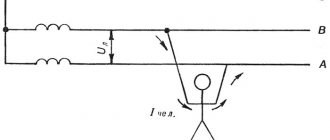
Voltage is the pressure from an electrical circuit's power source that moves charged electrons (current) through a conductive circuit, allowing them to do useful work (such as making a light bulb glow). In short: voltage = pressure, it is measured in volts (V).
Interesting materials:
What factors influence the location of agriculture? What films are considered science fiction? What films are coming out in March 2022? What fruit trees can be planted in spring? What fruits ripen at home? What fruits and vegetables do budgies like? What fruits and vegetables should dogs not eat? What fruits do Kakariki like? What are the functions of the essence? What are the functions of the Xiaomi fitness bracelet?
Disadvantages of using a contact rail
However, the advantages also come with disadvantages. Due to the fact that steel, due to its ferromagnetic properties, has a pronounced skin effect, it is not suitable for transmitting alternating current: due to the fact that the movement of charged particles in an alternating electric field will be grouped in the surface layer of a given metal, the useful cross-section of the conductor will change to a lesser extent, increasing electrical resistance.
In an overhead contact network, all live parts are located at a considerable height and do not pose any threat to others, and also remain “safe” from weather phenomena such as heavy snowfall. Electrical safety dictates many restrictions associated with the contact rail; basically, the rules boil down to the need to ensure that there are no people near the live rail, and the insulation of the rail.
At metro stations, if a passenger falls on the track, there is a special algorithm for getting him back after the stress is removed; a special ladder is used to climb to the station through the contact rail. It is also necessary to ensure 100% exclusion of people in the tunnel while trains are moving, and in the Russian metro for this purpose special monitoring devices are installed at all stations. In this case, the danger lies in the pantographs, which are located on both sides of the rolling stock. The presence of a contact rail on one side of the track in a tunnel can give a run-in hitch a false sense of security on the opposite side. Not only are moving pantographs themselves extremely dangerous structural elements to encounter in a narrow tunnel, but they are also energized if at least one of them, on any side of the car, touches the contact rail.
This is what the stairs to enter the metro station from the tracks look like. The staircase has a folding design
In general, of course, there are subways in which the contact rail is not isolated from the outside world at all, and electrical safety is ensured solely by organizational measures, but in Russia the contact rail must have an insulating casing (box), and this significantly increases the cost of the design.
Contact rail device
The contact rail is mounted directly into a porcelain insulator with a polyethylene gasket, which in turn is attached to the head of the holding bracket. The insulating box is attached directly to the head of the bracket. Thus, already at this level the contact rail remains a completely electrically insulated conductor. To supply voltage to it, a direct connection to the wire rail from the corresponding energy feeder is used.
Where the contact rail is connected to the feeder (note that the contact rail in this photo does not have a protective box)
The holding bracket is securely attached to the sleeper, and its height depends on the height of the track rails. Between the brackets a distance of up to 5.5 meters is maintained, and this distance does not depend on the length of the rails (by the way, the length of one rail is 12.5 meters).
Now there seems to be only one problem - abrasion of the contact shoe (which is pressed by the pantograph to the contact rail) on frequent joints. But the velvet path was invented not only for people, and for pantographs, contact rails are welded into single strands up to 100 meters long, with the obligatory presence of temperature joints to allow deformation-free expansion and contraction of the strand due to temperature changes. Several conductive pads must be welded onto the welded joint to reduce electrical resistance.
Pantograph shoe of a subway motor car
For smooth connection and disconnection of the pantograph shoe to the contact rail, end bends are used. Their design is quite simple; at the end of the bend, its height relative to the head of the track rail begins to increase until the surface of the contact rail becomes higher than the contact height of the shoe.
Source
What does the train power?
Classic electric trains receive energy from the contact wire or contact rail using current collectors. Current collectors can be placed on both motor and trailer cars; in the latter case, power is transmitted to the motor car through inter-car electrical cables.
Interesting materials:
What happens in the root division zone? What happened to Judas after the betrayal? What happened to Ostap? What did the Tin Woodman ask from Terrible Goodwin? What do they check at the check-in counter at the airport? What does Yeshua proclaim in his conversation with Pontius Pilate? What breaks down proteins, fats and carbohydrates? What does the number 3 mean? What develops singing? What's wrong with the TV, sound is there, no picture?
Prospects for the development of electric rolling stock
Today, due to the high cost of the current infrastructure and the presence of a huge fleet of rolling stock, it is not economically feasible to convert roads from direct current to alternating current, but instead of converting the contact network, engineers took a different route.
It is possible to change the rolling stock - the second way is to create dual-power electric locomotives capable of operating on both direct and alternating current, and switching operating modes on them is as automated as possible. Today, such machines not only exist on paper or as prototypes, such locomotives are successfully working for the benefit of Russian Railways - Double Power Electric Locomotives.
In preparing the material we used: Marquardt K. G. Contact network. 4th ed. reworked and additional Textbook for railway universities
Source
Urban and intercity electric transport have become familiar attributes of everyday life for modern people. For a long time now we have not thought about how this transport receives power. Everyone knows that cars are fueled with gasoline, bicycle pedals are pedaled by cyclists. But how are electric types of passenger transport powered: trams, trolleybuses, monorail trains, metro, electric trains, electric locomotives? Where and how is the driving energy supplied to them? Let's talk about this.
In the old days, each new tram service was forced to have its own power plant, since public electrical networks were not yet sufficiently developed. In the 21st century, energy for the tram catenary network is supplied from general purpose networks.
The power is supplied by direct current of relatively low voltage (550 V), which would simply not be profitable to transmit over long distances. For this reason, traction substations are located near the tram lines, at which alternating current from the high-voltage network is converted into direct current (with a voltage of 600 V) for the tram contact network. In cities where both trams and trolleybuses operate, these types of transport usually have a common energy supply.
In the territory of the former Soviet Union, there are two power supply schemes for overhead contact networks for trams and trolleybuses: centralized and decentralized. Centralized appeared first. In it, large traction substations equipped with several converting units served all lines adjacent to them, or lines located at a distance of up to 2 kilometers from them. Substations of this type are located today in areas of high density of tram (trolleybus) routes.
A decentralized system began to take shape after the 60s, when outbound lines of trams, trolleybuses, and metro began to appear, such as from the city center along the highway to a remote area of the city, etc.
Here, for every 1-2 kilometers of the line, low-power traction substations with one or two converter units are installed, capable of powering a maximum of two sections of the line, and each section at the end can be fed by a neighboring substation.
This way, energy losses are less, because the feeder sections are shorter. In addition, if an accident occurs at one of the substations, a section of the line will still remain energized from the neighboring substation.
In a trolleybus, the contact network is divided by sectional insulators into segments isolated from each other, each of which is connected to a traction substation using feeder lines (overhead or underground). This easily allows selective shutdown of individual sections for repairs in case of damage. If a fault occurs with the supply cable, it is possible to install jumpers on the insulators to power the affected section from the adjacent one (but this is an emergency mode associated with the risk of feeder overload).
The traction substation reduces high voltage alternating current from 6 to 10 kV and converts it into direct current, with a voltage of 600 volts. The voltage drop at any point in the network, according to regulations, should not be more than 15%.
The trolleybus contact network is different from the tram network. Here it is two-wire, the ground is not used to drain current, so this network is more complex. The wires are located at a short distance from each other, so particularly careful protection against proximity and short circuits is required, as well as insulation at the intersections of trolleybus networks with each other and with tram networks.
Therefore, special means are installed at intersections, as well as arrows at branching points. In addition, a certain adjustable tension is maintained, which protects the wires from tangling during the wind. That is why rods are used to power trolleybuses - other devices simply will not allow meeting all these requirements.
Trolleybus booms are sensitive to the quality of the contact network, because any defect can cause the boom to come off. There are standards according to which the bend angle at the point where the rod is attached should not be more than 4°, and when turning at an angle of more than 12°, crooked holders are installed. The current collector shoe moves along the wire and cannot turn with the trolleybus, so arrows are needed here.
Monorail trains have recently been running in many cities around the world: Las Vegas, Moscow, Toronto, etc. They can be found in amusement parks, zoos, monorails are used to explore local attractions, and, of course, for urban and suburban transport.
Some monorail trains are designed in such a way that they seem to be mounted on the track from above, just like a person sitting astride a horse. Some monorails are suspended from a beam below, resembling a giant lantern on a pole. Of course, monorails are more compact than conventional railways, but their construction is more expensive.
Some monorails have not only wheels, but also additional support based on a magnetic field. The Moscow monorail, for example, moves precisely on a magnetic cushion created by electromagnets. Electromagnets are located in the rolling stock, and permanent magnets are located in the guide beam web.
Depending on the direction of the current in the electromagnets of the moving part, the monorail train moves forward or backward according to the principle of repulsion of like magnetic poles - this is how a linear electric motor works.
In addition to rubber wheels, a monorail train also has a contact rail, consisting of three current-carrying elements: plus, minus and ground. The supply voltage of the monorail linear motor is constant, equal to 600 volts.
Subway electric trains receive electricity from the DC network - usually from the third (contact) rail, the voltage on which is 750-900 Volts. Direct current is obtained at substations from alternating current using rectifiers.
The contact of the train with the contact rail is carried out through a movable current collector. The contact rail is located to the right of the tracks. The current collector (the so-called “current collecting paw”) is located on the car bogie, and is pressed against the contact rail from below. The plus is on the contact rail, the minus is on the train rails.
In addition to the power current, a weak “signal” current flows along the track rails, which is necessary for the blocking operation and automatic switching of traffic lights. The rails also transmit information to the driver’s cabin about traffic light signals and the permitted speed of the metro train on this section.
An electric locomotive is a locomotive driven by a traction motor. The electric locomotive engine receives power from the traction substation through the contact network.
The electrical part of an electric locomotive as a whole contains not only traction motors, but also voltage converters, as well as devices that connect motors to the network, etc. The current-carrying equipment of an electric locomotive is located on its roof or hood, and is intended to connect electrical equipment to the contact network.
Adjusting the traction force and speed of an electric locomotive is achieved by changing the voltage at the motor armature and varying the excitation coefficient on commutator motors, or by adjusting the frequency and voltage of the supply current on asynchronous motors.
Voltage regulation is performed in several ways. Initially, on a DC electric locomotive, all its motors are connected in series, and the voltage on one motor of an eight-axle electric locomotive is 375 V, with a voltage in the contact network of 3 kV.
Electric power converters inside an electric locomotive are necessary to change the type of current and reduce the voltage of the contact network to the required values that meet the requirements of traction motors, auxiliary machines and other circuits of the electric locomotive. The conversion is carried out directly on board.
On AC electric locomotives, a traction transformer is provided to reduce the high input voltage, as well as a rectifier and smoothing reactors to produce direct current from alternating current. To power auxiliary machines, static voltage and current converters can be installed. On electric locomotives with asynchronous drives of both types of current, traction inverters are used, which convert direct current into alternating current of adjustable voltage and frequency, supplied to the traction motors.
An electric train or electric train in its classic form takes electricity with the help of current collectors through a contact wire or contact rail. Unlike an electric locomotive, electric train current collectors are located both on motor cars and on trailer ones.
If current is supplied to trailer cars, then the motor car receives power through special cables. Current collection is usually from the top, from the contact wire, and is carried out by current collectors in the form of pantographs (similar to tram ones).
Typically, current collection is single-phase, but there is also three-phase, when an electric train uses specially designed current collectors for separate contact with several wires or contact rails (if we are talking about the subway).
The electrical equipment of an electric train depends on the type of current (there are electric trains of direct current, alternating current or dual-system), the type of traction motors (commutator or asynchronous), and the presence or absence of electric braking.
Basically, the electrical equipment of electric trains is similar to the electrical equipment of electric locomotives. However, on most models of electric trains it is located under the body and on the roofs of the cars to increase passenger space inside. The principles of motor control for electric trains are approximately the same as for electric locomotives.
If you liked this article, share a link to it on social networks. This will greatly help the development of our site!
Source
How is the wind resistance of the contact network ensured?
Wind resistance is the ability of a contact network to provide current collection at a wind speed of design. ... In open areas with a steady wind directed across the track, as a rule, with ice, which changes the aerodynamic characteristics of the wires, self-oscillations of the contact suspension of the wires occur with a frequency of approx. 1 Hz.
Interesting materials:
What figure is called an angle in geometry? What geometric figure is called an angle on a plane? Which of the ancient Moscow streets retained its name during the Soviet years? What literature is called translated? What kind of car is called a crossover? What danger is called potential? What organization received its name during the reign of Alexander 1? Which plane is called the general plane? Which plane is called the level plane? Which subgroup is called a secondary group?
How many ECs are there in Russia?
Since 1926, mass electrification of the USSR railways began. In accordance with the GOELRO plan, by 1930 the electrification of railways with a total length of 372 km was provided. Currently, the total length of electrified railways in Russia
more than 43 thousand
Interesting materials:
How much does a 3 month old piglet eat? How many varieties of pears are there? How much does a Pig eat in a year? How much is diagonal 43? How much phosphorus is in Superphosphate? How many M10 nuts are in 1 kg? How many aerated concrete blocks are there in 1m2? How many aerated concrete blocks are in 1m3? How many aerated concrete blocks are in one cubic meter? How many gas blocks 400 in a cube?
