It is often necessary to reduce the rotation speed of a motor that performs certain tasks in a mechanism. Reducing the speed of an electric motor can be achieved using homemade devices and standard-made control circuits.
AC electric motors are often used in human activities, on metalworking machines, transport, crane mechanisms and other equipment. Motors convert alternating current energy into rotation of the shaft and components. Mainly asynchronous AC motors are used.
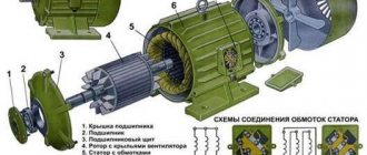
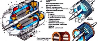
The rotor, as well as the stator of the motor, consists of coils of wire placed in a core made of special steel. The classification of electric motors follows from the method of laying the winding.
A winding of brass and copper rods is inserted into the core, and rings are installed along the edges. Such a coil of wire is called a short-circuited (SC) rotor. Small power electric motors have rods as well as discs that have been cast together. For electric motors with high torque, the parts are cast separately and then welded. The stator winding can be connected in two ways: triangle, star.
The phase rotor consists of a 3-phase rotor winding connected by slip rings and brushes to the power supply. The winding is star connected.
Calculation of the number of revolutions of an asynchronous motor
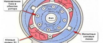
A common motor in machine tools and lifting devices is a squirrel-cage motor, so the calculation example should be taken for this type. The mains voltage is supplied to the stator winding. The windings are offset from each other by 120 degrees. The resulting electromagnetic induction field excites an electric current in the winding. The rotor begins to operate under the influence of EMC.
The main characteristic of engine operation is the number of revolutions per minute. We calculate this value:
n = 60 f/p, rpm;
where f is the network frequency, hertz, p is the number of stator poles (in pairs).
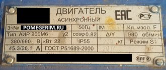
There is a plate with technical data on the motor housing. If it is not there, then you can calculate the number of revolutions of the equipment shaft yourself using other available data. The calculation is made in three ways.
- The calculation of the number of coils, which is compared with the standards for different voltages, follows the table:
- Calculation of operating speed by pitch of winding diameter using the formula:
2 p = Z1 / y, where 2p is the number of poles, Z1 is the number of slots in the stator, y is the winding pitch.
Select the appropriate engine speed from the table:
- We calculate the number of poles based on the core parameters using the formula:
2p = 0.35 Z1 b / h or 2 p = 0.5 Di / h,
where 2р – number of poles, Z1 – number of grooves, b – tooth size, cm, h – back height, cm, Di – tooth diameter, cm.
Based on the results of calculation and induction, the number of turns of the winding follows and is compared with the values of the motor according to the passport.
Mechanical characteristics
As the main one, it helps to conduct a detailed analysis of the operation of the electric motor. It expresses the direct dependence of the rotor speed on the electromagnetic torque n=f (M).
The graph shows that in sections 1-3 the machine operates stably. 3-4 - immediate segment of unstable work. Ideal idle speed corresponds to point 1.
Point 2 - nominal operating mode. Point 3 - the rotation speed has reached a critical value. Starting torque Mstart - point 4.
Our readers recommend! To save on electricity bills, our readers recommend the 'Electricity Saving Box'. Monthly payments will be 30-50% less than they were before using the saver. It removes the reactive component from the network, resulting in a reduction in load and, as a consequence, current consumption. Electrical appliances consume less electricity and costs are reduced.
There are technical methods for calculating and constructing mechanical characteristics taking into account data from the passport.
At the initial point 1 n0=60f/p (p is the number of pole pairs). Since nn and Mn are directly the coordinates of point 2, the rated torque is calculated using the formula Mn = 9.55*Рн/ nn, where Рн is the rated power. The value of nn is indicated in the engine passport. At point 3 Mkr=Mnλ. Starting torque at point 4 Mstart=Mn*λstart (values of λ, λstart - from the passport).
A mechanical characteristic constructed in this way is called natural. By changing other parameters you can obtain an artificial mechanical characteristic.
The results obtained make it possible to analyze and harmonize the mechanical properties of the engine itself and the working mechanism.
How to change the engine speed?
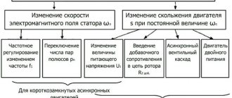
You can change the speed of the rotating moment of the equipment mechanism in various ways, for example, mechanical gearboxes with gear shifts, clutches and other devices. But this is not always possible. In practice, 7 methods are used to correct the rotation speed of variable speed drives. All methods are divided into two main directions.
- Correction of the magnetic field by influencing the frequency of the current, reducing or increasing the number of pole pairs, voltage correction. The direction is typical for motors with a squirrel-cage (SC) rotor.
- Slip is corrected by supply voltage, adding another resistor to the rotor circuit circuit, installing dual supply, or using a cascade of valves. This direction is used for rotors with phases.
Adjusting frequency and voltage using a frequency converter, by creating an additional coil with switching poles of pairs, are the most popular methods.
Variable Frequency Drives
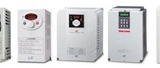
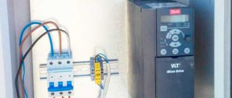
Installations such as variable-frequency drives (VFDs), also called frequency converters (FCs) ). These settings allow you to change the frequency and amplitude of the three-phase voltage supplied to the electric motor, due to which a flexible change in the operating modes of the control mechanisms is achieved.
High Voltage Variable Frequency Drive
VFD design
Let's give a brief description of existing frequency converters.
Structurally, the converter consists of functionally related blocks: input transformer block (transformer cabinet); a multi-level inverter (inverter cabinet) and a control and protection system with an information input and display unit (control and protection cabinet).
The input transformer cabinet transfers energy from the three-phase power supply to a multi-winding input transformer, which distributes the reduced voltage to a multi-level inverter.
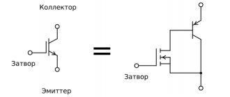
A multilevel inverter consists of unified cells - converters. The number of cells is determined by the specific design and manufacturer. Each cell is equipped with a rectifier and a DC link filter with a bridge voltage inverter using modern IGBT transistors (insulated gate bipolar transistor). The input AC current is initially rectified and then converted into alternating current with adjustable frequency and voltage using a solid-state inverter.
The resulting sources of controlled alternating voltage are connected in series into links, forming a voltage phase. The construction of a three-phase output power system for an asynchronous motor is carried out by connecting links according to the “STAR” circuit.
The protection control system is located in the control and protection cabinet and is represented by a multifunctional microprocessor unit with a power supply system from the converter's own power source, an information input/output device and primary sensors of the converter's electrical operating modes.
Common regulator circuits
There are many frequency converters for asynchronous motors, as well as various regulators for them. It is possible to independently make a device for adjusting the frequency using transistors or thyristors. The device works both in everyday life and for machine tools, crane mechanisms, and various adjustable drive units.
A powerful frequency and voltage regulator is shown in the diagram. The device smoothly changes drive parameters, saves energy, and reduces maintenance costs.
To apply this scheme in everyday life, it is difficult. If you use a triac as a working element, the circuit is simplified and looks different.
The adjustment will take place by operating a potentiometer, which determines the phase of the input pulse and opens the triac.
The effect of operating machines that process metal and lifting devices also follows from the rotation of the engine, as do its operational parameters themselves. There are many devices on sale for adjusting frequency, but it is quite possible to assemble such a device on your own.
How to choose a frequency converter?
If you analyze the prices and functions of frequency converters, you can understand that the price determines the number of built-in functions of the frequency converter. Expensive models have great functionality. But to select a device, it is better to be guided by the required conditions of use.
- Frequency generators come with two types of control: scalar and vector. With scalar control, the device operates at certain values of the output potential difference and frequency; they work in primitive household appliances, for example, fans. With vector control, the current strength is set quite accurately.
- When choosing a device, power parameters play a decisive role. The amount of power expands the scope of use and simplifies maintenance.
- When choosing a device, the operating voltage range of the network is taken into account, which reduces the risk of its failure due to sudden changes in potential difference. If the voltage increases excessively, the network capacitors may explode.
- Frequency is an important factor. Its value is determined by production requirements. The lowest value indicates the possibility of using the speed in the optimal operating mode. To obtain a larger frequency range, frequency generators with vector control are used. In reality, inverters with a frequency range of 10 to 10 Hz are often used.
- A frequency converter that has many different outputs and inputs is convenient to use, but its cost is higher and configuration is more difficult. There are three types of frequency connectors: analog, discrete, digital. Reverse communication of input commands is carried out through analog connectors. Digital terminals input signals from digital type sensors.
- When choosing a frequency converter model, you need to evaluate the control bus. Its characteristics are matched to the inverter circuit, which determines the number of pads. The best choice is a frequency generator with a reserve number of connectors for further modernization of the device.
- Frequency drivers that can withstand heavy overloads (15% higher than the motor power) have preferences when choosing. To avoid making mistakes when purchasing a frequency converter, read the instructions. It contains the main parameters for operating the equipment. If you need a device for maximum loads, then you need to choose a frequency converter that keeps the current at peak operation higher than 10% of the nominal value.
Driving at low speeds with early shifting
Often, driving school instructors and old drivers recommend that beginners drive “tight” - switch to higher gear when the crankshaft reaches 1500–2000 rpm. The former give advice for safety reasons, the latter out of habit, because previously the cars had low-speed engines. Nowadays, such a mode is only suitable for a diesel engine, whose maximum torque is in a wider speed range than that of a gasoline engine.
Not all cars are equipped with tachometers, so inexperienced drivers with this driving style should be guided by driving speed. The early switching mode looks like this: 1st gear - moving from a standstill, transition to II - 10 km/h, III - 30 km/h, IV - 40 km/h, V - 50 km/h.
Such a switching algorithm is a sign of a very calm driving style, which gives an undoubted advantage in safety. The downside is the increased wear rate of power unit parts and here’s why:
- The oil pump reaches its rated output from 2500 rpm. The load at 1500–1800 rpm causes oil starvation, especially the connecting rod bearings (liners) and compression piston rings are affected.
- The combustion conditions of the air-fuel mixture are far from favorable. Carbon deposits are heavily deposited in the chambers, on valve plates and piston heads. During operation, this soot heats up and ignites the fuel without a spark at the spark plug (detonation effect).
- If you need to sharply increase engine speed when driving at the very bottom, you press the accelerator, but acceleration remains sluggish until the engine reaches its torque. But as soon as this happens, you engage a higher gear and the crankshaft speed drops again. The load is large, there is not enough lubrication, the pump pumps antifreeze poorly, which causes overheating.
- Contrary to popular belief, there is no gas savings in this mode. When you press the gas pedal, the fuel mixture becomes richer, but does not burn completely, which means it is wasted.
Owners of cars equipped with an on-board computer can easily convince themselves of the uneconomical nature of driving under tension. It is enough to turn on the display to show instantaneous fuel consumption.
This type of driving greatly wears out the power unit when the car is operated in difficult conditions - on dirt and country roads, with a full load or a trailer. Owners of cars with powerful engines of 3 liters or more, capable of sharp acceleration from the bottom, should not relax either. After all, to intensively lubricate the rubbing parts of the engine, you need to keep the crankshaft at least 2000 rpm.
How to connect a frequency converter
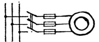
If the cable for connection is 220 V with 1st phase, a “triangle” circuit is used. You cannot connect a frequency converter if the output current is higher than 50% of the rated value.
If the power cable is three phase 380 V, then a “star” circuit is made. To make it easier to connect power, contacts and terminals with letter designations are provided.
- Contacts R, S, T are intended for connecting the power supply in phases.
- Terminals U, V, W serve as the motor connection. To reverse, just change the connection of the two wires to each other.
The device must have a block with a ground connection terminal. More details on how to connect are here.
How to maintain frequency converters?
For long-term operation of the inverter, it is necessary to monitor its condition and follow the maintenance instructions:
- Clean internal elements from dust. You can use a compressor to remove dust with compressed air. A vacuum cleaner is not suitable for these purposes.
- Periodically monitor the condition of the components and replace them. The service life of electrolytic capacitors is five years, fuse links are ten years. Cooling fans last 3 years before replacement. The wire loops have been used for six years.
- Monitoring the DC bus voltage and the temperature of the mechanisms is a necessary measure. At elevated temperatures, the thermal conductive paste dries out and damages the capacitors. Every 3 years, a layer of conductive paste is applied to the power terminals.
- The operating conditions and operating hours must be strictly observed. The ambient temperature should not exceed 40 degrees. Dust and humidity negatively affect the condition of the working elements of the device.
Frequency converter payback
Electricity is constantly becoming more expensive, and managers of organizations are forced to save in different ways. In industrial production, most of the energy is consumed by mechanisms with electric motors.
Manufacturers of devices for electrical machines and units offer special devices and instruments for controlling electric motors. Such devices save electrical energy. They are called inverters or frequency converters.
The financial costs of purchasing a frequency generator do not always justify the cost savings, since their cost is comparable to the cost of saved energy. It is not always possible to quickly equip a mechanism with an inverter. What difficulties arise in this? Let's look at ways to start asynchronous motors to understand the advantages of inverters.
Types of speed control
There are several types of control of an asynchronous electric motor, among which the most common in recent years has been the method of vector or vector sensorless speed control. It is often found in a frequency converter, which initially uses scalar control without terminals to connect a speed sensor.
Actually, the type of regulation of an asynchronous motor by a frequency converter depends on the class of the latter. And frequency regulators are divided according to several criteria.
- By type of control - manual and automatic control devices.
- Depending on the type of output load, the frequency converter is divided according to the method of execution:
- for devices for electric drives of pumping and fan equipment;
- drive mechanisms for general industrial purposes;
- frequency converters for electric motors that are operated in difficult conditions (with overloads).
Frequency converters of the latest generations, in addition to variations that differ in design, may also have a different set of functions. The latter include 2 types of control (manual and automatic) for the rotation speed and its direction, a potentiometer on the main panel, and a system for adjusting output frequency ranges (0–800 Hz).
