How to make a 24 volt DC power supply
If an electrical circuit is not powered by a battery, then it requires a DC power source to maintain optimal voltage and current levels. The DC power module supplies AC power from the wall outlet, converting it to DC power, and stabilizes the output power before passing it on to the rest of the circuit. This piece of technology is a critically integral part of circuit and electronics design, whether it is used by a professional or an amateur, you must understand how the power supply works. This guide will walk you through creating a 24 volt DC power supply. Power supplies for LEDs can be viewed on the supplier's website.
Security Considerations
Before building a 24-volt DC power supply, you need to learn about some of the safety aspects that come with this project. If something goes wrong, the connected power source can seriously injure you when directly connected to the AC power in your home. There are steps you can take to minimize the chance of injury. You should consider building this project on an antistatic mat or you can wear antistatic gloves. Although the components used are relatively reliable, it is best to avoid static interactions between your hands and the power source. More importantly, make sure the power is always off while you are building or making changes to the circuit. Double check everything before turning on the power.
Transformer connection
The main part in any DC power supply is the voltage transformer. This component takes the entire AC power level and scales it to a usable range at a certain ratio. To get to 24 volts, you need to know the voltage supplied from the electrical outlet. In the US, as well as some other countries, it is 110 VAC. For the rest of the world, wall voltage runs around 220 VAC. This means, for example, that American builders should purchase transformers with a 4.5:1 ratio that scales voltage up to
24.4 V. Conversely, in Russia and other countries around the world, workers must use a transformer with a 9:1 ratio.
To connect the transformer, attach the ground wires from the power supply to the two input terminals of the transformer using some solder. The two transformer outputs are ground and scale the output voltage.
Implementation of a bridge rectifier
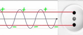
AC voltage constantly fluctuates between positive and negative potential in a sine wave. In order to convert this direct current voltage to positive 24 volts, you need to take the absolute voltage value from the output transformer using a bridge rectifier.
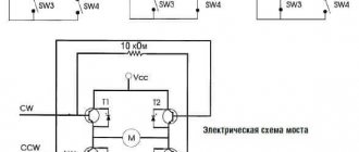
There are two ways to implement a bridge rectifier into a DC power supply. The first is to use a manufactured bridge rectifier. This electrical component has four pins. You need to connect the two input pins to the transformer outputs to each other through a 1-kOhm resistor. The side of the resistor attached to the negative output of the bridge rectifier should also go to ground, while the connection between the positive output of the bridge rectifier and the resistor at the output should serve as the termination of the connection.
Alternatively, you can use four diodes to make your own bridge rectifier. To do this, you need to connect all four diodes in series so that they form a ring. Make sure that two adjacent diodes are polarized in the same direction, while the other two are in the opposite direction. The transformer outputs are connected to a junction in the middle of each of two pairs of diodes that face the same direction. The positive and negative outputs of the rectifier bridge can be made from the other two nodes in the diode ring. These results should be connected to the 1K load resistor, ground, and output circuit as described in the previous paragraph.
Adding a Low Pass Filter
In order to stabilize the power supply, implement a passive RC low-pass filter, you need to implement a 100-uF capacitor in parallel with the load resistor, where this capacitor should go to ground. You can use an oscilloscope to check the RC filter to make sure it is working correctly.
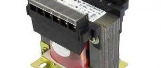
The device of a simple transformer
The main element of the transformer is the relay. The coils themselves are installed with different windings. Magnetic cores are available with cores. In terms of current conductivity, they differ quite significantly. It is also important to mention that some modifications include special extenders. In this case, much depends on the operating frequency parameter.
Insulators in transformers are designed to protect the core from overloads. To rectify direct current, transceivers are installed in devices. They are produced in orthogonal and tuning types.
Application areas of LED strips
Using tape to illuminate a mirror
The main function of LED devices is to organize artificial lighting in a specific room or outside a building. In this case, the LED strip replaces conventional light bulbs, being located along the perimeter of the ceiling or in a pre-marked area. This approach to decorating free spaces allows you to improve the quality of the light picture and evenly illuminate the objects being served. Thanks to this, it is possible to increase the comfort of people’s stay in rest areas or in the work area.
Typically, for these purposes, tapes with elements of increased brightness, characterized by a warm white glow, are used. The use of low-power lighting devices, even if they are evenly distributed around the entire perimeter, will require the installation of an additional lamp.
Use for decorative purposes
LED strip under a suspended ceiling
Modern LED lighting devices are very popular in decorating practice and are widely used in the following areas:
- lighting of shelves, construction niches and stairs;
- architectural zoning of work spaces;
- highlighting elements of landscape areas with flower beds and trees;
- decoration of building facades, as well as individual architectural details.
In addition, their help is resorted to when it is necessary to focus attention on elements of the environment: furniture, mirrors, paintings and other objects. To meet constant demand, manufacturers have developed many varieties of LED strips, which provide various visual effects.
Downgrade modifications
A step-down transformer from 220 to 24 volts is often found with a power of 100 watts or more. Devices of this type are used, as a rule, for electric drives. Many models have magnetic cores with relays with strip cores. It is also important to note that the windings in 3 kW devices are installed concentrically. However, modifications with three-layer analogues are available on the market. There are two total outputs for step-down devices.
Some modifications are available with terminals. A step-down transformer 220 to 24 volts weighs no more than 5 kg. The models differ quite significantly in terms of current conductivity. In this case, the type of transceiver must be taken into account. Domestic transformers are mainly sold with orthogonal analogues. However, foreign companies prefer trimmed transceivers. The current overload indicator for models is on average 5.5 A. Some devices are available with switches for phase adjustment.
Toroidal models
The toroidal transformer 220 to 24 volts differs in that it contains a comparator. Due to the specified element, the clock frequency from the network is changed. It is also important to mention that many devices are equipped with zener diodes. The magnetic cores in the devices are installed as usual.
The windings for transformers themselves are of the concentric type. These devices are most often used for low-power engines. They are also suitable for many types of compressors. As a rule, there are no regulators in devices. Insulators are used of the composite type. On average, the current conductivity parameter of the models does not exceed 50 µS. In turn, devices with a power of 80 W can withstand an overload of 3 A.
LED strip brightness 24V
LED strips are offered in a wide range of brightness, which directly depends on the installed LEDs and the density of their placement on the LED strip. Above, we already looked at the LEDs installed on LED strips, when we looked at the power of LED strips and the brightness of each type of LED was indicated in the table.
Let's take, for example, one of the popular LED strips with SMD 5050 LEDs. The power of one such LED is up to 0.3 W, the emitted luminous flux is 25 lm. In a powerful LED strip, the density of such LEDs is 120 pieces per 1 meter, which is more than 25 W with a luminous flux of about 3000 lm. Even one meter of such tape should be enough to illuminate a large room in a three-room apartment.
Oil models
The 220 12–24 volt oil transformer is equipped with a special heat exchanger. Channels are used directly for coolant. The cores in many modifications are of the tape type. Three-layer windings are most often used. Relays deserve special attention. They are installed with different conductivity. On average, for oil configurations this parameter fluctuates around 60 µS.
Coils in devices are installed with magnetic cores. There are two direct terminals for connecting equipment. Some configurations are produced with terminals. Oil-based devices are ideal for electric drives. Transceivers in all models are installed only of the orthogonal type.
How to make a device with your own hands?
Making a 220 to 24 volt transformer with your own hands is quite difficult. First of all, for a step-down modification you will need a large coil with good current conductivity. In order to ensure stable operating frequency, the winding must be of concentric type. Directly to connect equipment, terminals are used, which are simply conductors.
In this case, conventional expanders are installed. They can be used from any broken transformer. If we consider modifications with switches, then we will have to make a separate stand for them. To prevent failures from occurring frequently, insulators are used. Nowadays, composite analogues are considered to be the most reliable.
80 W model
A 220 to 24 volt DC 80 watt transformer is most suitable for conventional compressors. Models of this type are quite rare in production. Their energy consumption is insignificant, but the power for a normal electric drive is definitely not enough. Magnetic cores in devices are usually used with a low-voltage winding.
In this case, the cores are of the stamped type. If we consider configurations with high current conductivity, then they have special comparators. However, most often conventional bends are installed. There are also models with stabilizers. In this case, the overload current parameter averages 3.5 A. Switches on 80 W models are never used.
Color of LED strips 24V
If we consider only monochrome single-color LED strips, then their color will be determined by the installed LEDs. LEDs are generally installed in standard colors: blue, red, yellow, green.
Much less common are LED strips of other colors: crimson, turquoise, violet, ultraviolet and infrared. LED strips in the infrared and violet spectrum are special and are not usually used in everyday life.
Infrared, for example, can be used to illuminate objects for night vision cameras, and ultraviolet are used in greenhouses to illuminate plants or in nightclubs to make luminescent paints glow brightly in the dark.
LED strips with white LEDs are probably one of the most popular now. They are further divided according to shades of white into three different types: warm white, neutral and cool.
These three types of white shades correspond to certain thermal temperature ranges on the Kelvin scale: - warm white up to 3500 K; — neutral white from 3500 K to 5200 K; — cold white above 5200 K.
100 W device
A 220 to 24 volt (100W) transformer can be used for electric drives. Many modifications are equipped with reliable protection systems. Most often, manufacturers indicate the IP20 marking. All this suggests that the model’s grounding system is used with composite insulators. If we talk about magnetic cores, they are used with a secondary winding.
Quite often, cores are of the sheet type. However, there are many stamped analogues on the market. In terms of quality, they are not much inferior to sheet cores. Current conductivity for 100 W configurations averages 70 µS. If we talk about overloads, then a lot in this situation depends on the manufacturer. Devices with transceivers are rare. However, 100 W transformers with stabilizers are in great demand.
Advantages of electronic converters
The main advantages of devices built on the basis of ET include the following features of the circuit:
- the output transformer of the power supply will not start without connecting a load to it - it will go into active mode only if a lamp with a light bulb is connected to it;
- in addition to the gentle operation of electronic circuit elements, this property of the electric vehicle allows you to save on consumed electricity;
- The product easily implements a system of protection against dangerous overloads and short circuits.
More complex half-bridge circuits are often taken as a sample used for making a home-made power supply on such a transformer. They are usually built on the basis of drivers such as IR2153 or similar electronic components. As an additional option, they are equipped with an indicator LED that signals the presence of high-frequency oscillations.
Transformer 120 W
Transformer 220 to 24 volts 120 W is suitable for electric motors of different power. The cores are installed in sheet type in many configurations. Magnetic cores, in turn, are available with a high-voltage winding. The devices have two pins as standard. Some models are produced with terminals for connection to equipment. There are different cooling systems today. However, most often we are talking about a normal decrease in temperature due to air circulation.
Coils in transformers are often mounted on support rings. In some cases, models have extenders. Switches are also used in transformers. Transceivers are used of both orthogonal and tuning types. In this case, much depends on the operating frequency of the network. If it does not exceed 40 Hz, then you can safely use orthogonal transceivers. Otherwise, only trim components are suitable for normal operation of the device. Stabilizers are used quite rarely.
What is LED strip 24V
Everyone is now familiar with LED strips, and when this name is mentioned, it immediately becomes clear what we are talking about. If we define a 24V LED strip, then it is a special thin printed circuit board with a width of 8 to 20 mm with contact pads on one side, to which SMD LEDs and current-limiting resistors are soldered.
The LEDs on such a board are placed at an equal distance from each other. To connect all the LEDs on a long 24V LED strip there are two contacts to which the 24V voltage is connected, observing the polarity.
Single band devices
A single-range 220 to 24 volt transformer is capable of operating in a network with a frequency below 45 Hz. In this case, comparators are installed in all models. Due to them, the current conductivity indicator can be easily stabilized. Transceivers are mostly orthogonal. The insulators themselves are specified for composite models. Magnetic cores for current conversion are used on the high-voltage winding. In this case, the coils must have support rings. Single-range transformers do not have heat exchangers.
Multi-band modifications
A multi-range transformer 220 to 24 volts can be used quite easily from a network with a frequency of over 45 Hz. Jumps in the system rarely occur in models. Due to this, electrical equipment works better, and energy consumption is not very high. Comparators in such modifications are of the two-pole type.
The current conductivity of the models exceeds 80 µS. In turn, the overload parameter is usually 5.5 A. Insulators in this case are installed on the taps. Switches are used to avoid various electromagnetic faults. Heat exchangers in structures are used in various capacities. To strengthen them, supports and slats are used. Many models have a liquid cooling system. Magnetic cores are used with high-voltage windings.
Transformers with dielectrics
Models with dielectrics are used for compressors. In production, devices of this type are quite in demand. They are capable of operating from a single-phase circuit.
It is also important to consider that the frequency of the models is on average 35 Hz. Thus, large current overloads rarely occur. Insulators are not used in the presented models. The dielectrics are installed directly near the magnetic core.
Let's consider the operation of a 24-volt stabilizer using the example of a power source for an air humidifier for an incubator. His nutrition is precisely this value. The boost stabilizer circuit is shown in the figure. Its main element is the UC 3843 microcontroller. This circuit was given in the documents for this chip model.
Features of the circuit
The input voltage range is in the range of 9.5-15 V. We ordered a humidifier with a current consumption of 0.5 A, so the rated current consumption of the converter was chosen twice as high, that is, 1 A.
The output voltage is 24 V. The outside view of this assembled device is shown in the photograph, and the figure shows the printed circuit board.
Instead of a powerful Schottky diode, an S 10C 40C assembly diode was used. You can use other Schottky series diodes with a current in the forward direction of at least 5 A, and a voltage in the reverse direction of about 40 V. Instead of a transistor, any field-effect transistor with the “n” channel type, which is designed for 50 V drain-source voltage, is suitable for switching.
The optimal choice would be transistors with minimal open channel resistance. You can select the required field-effect transistor in any online store. The circuit under consideration uses an NDP 603 AL transistor. The throttle is equipped with a Ch22 core with an outer diameter of cups of 22 mm. The core is assembled with a gap of 0.22 mm. The choke coil has 18 turns of enameled winding wire with a diameter of 1 mm.
The inductor is fixed to the board using an insulating washer. Instead of such a core with ferrite cups, you can use a yellow-white ring. These rings are used in computer power supplies. In this case, the outer diameter of the ring is 20.2 mm, and the inner diameter is 12.6 mm. Its height is 6.35 mm. The number of turns of the coil is 33 pieces from the same wire.
It is possible to use a ring with a larger diameter, reducing the number of turns to 25. Diodes and transistors are fixed directly to the device body, without fail through dielectric spacers. With such a converter output power, the diode and transistor can operate without a cooling radiator using pulse mode.
But in emergency cases, the optimal solution would be to use small metal plates as heat removal. If the installation is carried out correctly and all parts are in good working order, then such a 24-volt stabilizer will begin to work immediately.
Flyback switching power supply
This is one of the types of switching power supplies that have galvanic isolation of both primary and secondary circuits. This type of converter was immediately invented, which was patented back in 1851, and its improved version was used in ignition systems and in horizontal scanning of televisions and monitors, to supply high-voltage energy to the secondary anode of the kinescope.
The main part of this power supply is also a transformer or maybe a choke. There are two stages in its work:
- Accumulation of electrical energy from the network or from another source;
- Output of accumulated energy to the secondary circuits of the half-bridge.
When the primary circuit opens and closes, current appears in the secondary circuit. The role of the disconnecting key was most often performed by a transistor. To find out the parameters of which you must use the reference book. This transistor is most often controlled by a field-effect transistor using a PWM controller.
PWM controller control
The conversion of the mains voltage, which has already passed the rectification stage, into rectangular pulses is performed with some periodicity. The turn-off and turn-on period of this transistor is performed using microcircuits. The PWM controllers of these keys are the main active control element of the circuit. In this case, both forward and flyback power supplies have a transformer, after which re-rectification occurs.
In order to ensure that the output voltage in the SMPS does not drop with increasing load, a feedback loop was developed that was inserted directly into the PWM controllers
This connection makes it possible to completely stabilize the controlled output voltage by changing the duty cycle of the pulses. Controllers operating on PWM modulation provide a wide range of output voltage changes
Microcircuits for switching power supplies can be of domestic or foreign production. For example, NCP 1252 are PWM controllers that have current control and are designed to create both types of pulse converters. Master pulse generators of this brand have proven themselves to be reliable devices. NCP 1252 controllers have all the quality features to create cost-effective and reliable power supplies. Switching power supplies based on this microcircuit are used in many brands of computers, televisions, amplifiers, stereo systems, etc. By looking in the reference book, you can find all the necessary and detailed information about all its operating parameters.
24 V DC voltage stabilizer
In the wide field of radio-electronic devices, the KR 142 EN 9B microcircuit as a stabilizer with three terminals with a constant voltage of 24 V can be used to connect logic circuits, as well as measuring instruments, audio devices with high-quality playback.
External elements can be used to speed up transition processes. An input capacitor is needed only in cases where the regulator is located at a distance of no more than five centimeters from the capacitor, which acts as a power supply filter.
Main technical parameters:
- Internal fault current limiter.
- Transistor output protection.
- Internal thermal protection.
- No need for external elements.
- Allowable output current 1 ampere.
- Entrance.
- Grounding.
- Exit.
Car stabilizer for 24 V
Let's consider one simple electronic homemade product. This will be a 24 volt stabilizer. But this is not an ordinary stabilizer, but a reliable and powerful linear device. We've been using it for a long time. The radar detector in the car is connected to power through this circuit. It is equipped with internal stabilization. However, sometimes it fails, and one day the detector failed.
We did not send it in for repairs, but simply pulled out the burnt stabilizer from it and connected it from a separate stabilizer made by ourselves. It has been working fine for about two years now. But now a similar scheme is needed again. Not just for a car, but for household purposes.
It is necessary to connect a low frequency amplifier to the power supply. Its power supply voltage is 24 volts. The stabilizer is based on the L 7824 microcircuit. This microcircuit can provide a current of 1.5 A. However, at a significant current, it gets very hot and reduces its stability. To solve this problem and increase the current with which stabilization will take place, a simple circuit has been developed.
In this circuit, amplification will occur through the operation of a transistor connected in parallel. The circuit is simple and does not require expensive, scarce parts. It can be mounted using a hinged installation method to check operation.
A cooling radiator is required for such a circuit, since the circuit is linear and significant power is dissipated on the semiconductor. The linearity of the circuit is a positive point for the amplifier, since there is no extraneous interference from the PWM modulator. The circuit board was etched in a solution of citric acid and hydrogen peroxide.
Protection
As I said at the beginning of the article, the power supply must protect PC components from damage in emergency situations. Therefore, when choosing a block, you need to look at the presence of protection circuits.
- Over-Voltage/Undervoltage Protection (OVP/UVP): OVP protects the hardware from problems with the block itself, and UVP protects the block from high external voltage.
- Single Line Overload Protection (OCP): Prevents all power from being sent to any one power line. This is done to ensure that any component cannot fail due to excess power.
- Overload Protection (OPP): Roughly speaking, OCP on the 12V line is the OPP for the entire power supply.
- Overheat protection (OTP).
- Short Circuit Protection (SCP).