H.2. CLASSIFICATION OF ELECTRICAL DEVICES
Electrical measuring instruments can be classified according to the following criteria: measurement method; the type of quantity being measured; type of current; degree of accuracy; operating principle
. There are two measurement methods: 1) the direct assessment method, which consists in the fact that during the measurement process the measured value is immediately assessed; 2) the comparison method, or the zero method, which serves as the basis for the operation of comparison devices: bridges, compensators. Electrical measuring instruments are distinguished by the type of quantity being measured: for measuring voltage (voltmeters, millivoltmeters, galvanometers); for measuring current (ammeters, milliammeters, galvanometers); for measuring power (wattmeters); for energy measurement (electric meters); for measuring the phase shift angle (phase meters); for measuring current frequency (frequency meters); for measuring resistance (ohmmeters), etc. Depending on the type of current being measured, devices of direct, alternating single-phase and alternating three-phase current are distinguished. According to the degree of accuracy, devices are divided into the following accuracy classes: 0.05; 0.1; 0.2; 0.5; 1.0; 1.5; 2.5; and 4.0. The accuracy class should not exceed the given relative error of the device, which is determined by the formula:
where A is the readings of the device being verified; A0 - readings of the reference device; Amax - maximum value of the measured value (measurement limit). Depending on the principle of operation, systems of electrical measuring instruments are distinguished. Devices of the same system have the same operating principle. There are the following main instrument systems: magnetoelectric, electromagnetic, electrodynamic, induction.
3.3. MAGNETOELECTRIC SYSTEM
The devices of this system (Fig. 3.3.1) contain a permanent magnet - 1, to which poles - 2 are attached. In the interpolar space there is a steel cylinder - 3 with a frame glued to it - 4. Current is supplied to the frame through two spiral springs -5. The operating principle of the device is based on the interaction of the current in the frame with the magnetic field of the poles.
This interaction causes a torque
, under the action of which the frame and along with it the cylinder will rotate at an angle.
The coil spring in turn produces a counter torque
. Since the torque is proportional to the current, , and the counteracting torque is proportional to the angle of twist of the springs, we can write:
where k and D are proportionality coefficients. From what has been written it follows that the angle of rotation of the frame
and the current in the coil
where is the sensitivity of the device to current, determined by the number of scale divisions corresponding to a unit of current; CI is a constant current, known for each device. Consequently, the measured current can be determined by the product of the rotation angle (measured on a scale) and the current constant CI. The advantages of this system include high accuracy and sensitivity, low energy consumption. Disadvantages include the complexity of the design, sensitivity to overloads, and the ability to measure only direct current (without additional means).
3.4. ELECTROMAGNETIC SYSTEM
Devices of this system (Fig. 3.4.1) have a fixed coil - 1 and a moving part in the form of a steel core - 2, connected to an indicator needle - 3, an opposing spring - 4. The measured current, passing through the coil, magnetizes the core and draws it into the coil . When the torque and braking torques are equal, the system will calm down. The measured current is determined by the angle of rotation of the moving part. The average torque value is proportional to the square of the measured current:
Since the braking torque created by the spiral springs is proportional to the angle of rotation of the moving part, we will write the equation of the device scale in the form:
In other words, the angle of deflection of the moving part of the device is proportional to the square of the effective value of the alternating current.
The main advantages of electromagnetic force include: simplicity of design, operational reliability, and resistance to overloads. The disadvantages include: low sensitivity, high energy consumption, low measurement accuracy, uneven scale.
Induction devices
to contents
Device. The induction device consists of two stationary electromagnets 2 and 3 (Fig. 329) and a movable aluminum disk 4, mounted on the same axis with the arrow.
When alternating currents I1 and I2 pass through the coils of electromagnets, two magnetic fluxes F1 and F2 are created, shifted relative to one another in phase, which penetrate the disk. These flows, when changing, induce eddy currents Iв1 and Iв2 in the disk. As a result of the interaction of eddy currents with the magnetic fields of both electromagnets (current Iв1 with flow Ф2 and current Iв2 with flow Ф1), a torque M arises, under the influence of which the moving part of the device rotates. The counteracting moment in voltmeters, ammeters and wattmeters is created by a spiral spring 1 or stretch marks.
The average value of the torque M over the period is proportional to the product of the effective values of magnetic fluxes Ф1 and Ф2 and the sine of the phase shift angle φ between these fluxes:
M = c1φ1φ2 sinφ (102)
where c1 is a constant value for the device.
Rice. 329. Design of an induction measuring mechanism
To obtain the greatest value of torque, the phase shift angle between the flows is set to 90° by including additional active and reactive resistances in the coil circuits. Under this condition, the average torque in voltmeters and ammeters will be proportional to the product of the effective values of the currents I1 and I2 flowing through the coils of the electromagnets. This value will also determine the angle of rotation of the arrow:
φ = kI1I2 (103)
In wattmeters Δ = kUI cos φ = kP, since the current I1 is proportional to the current I in the circuit, I2 is proportional to the voltage U, and the angle φ is equal to the angle 90° - φ.
Application. Induction devices, as well as electrodynamic ones, can be used as an ammeter, voltmeter and wattmeter. The electromagnet coils are turned on in these cases in the same way as the coils of an electrodynamic device (see Fig. 327).
The advantages of induction devices are high resistance to overloads, high torque and low sensitivity to external magnetic fields. Disadvantages include relatively low accuracy and dependence of readings on alternating current frequency and temperature influences.
Induction devices are used mainly as wattmeters and electricity meters in industrial installations and on AC electric locomotives.
Scheme of an induction single-phase electric meter:
1 – electromagnet of the series circuit (current); 2 – parallel circuit electromagnet (voltage); 3 – counting mechanism; 4 – braking mechanism (permanent magnet, which creates a counteracting torque necessary to ensure unambiguous measurement); 5 – aluminum disk; 6 – load in the circuit (for example, lighting lamps); Фu – flux created by the current in the voltage circuit (parallel to the load); Фi – flux created by load current
to contents
Did you know,
What is the focus of Michelson's experiment?
The A. Michelson, Michelson - Morley experiment
is truly a circus trick that hypnotized physicists for 120 years.
The fact is that in its formulation and conclusions a substitution was made, similar to the substitution in a school joke problem on intelligence, which asks: - How many apples are there on a birch tree, if there are 5 on one branch, 10 on another branch, and so on? At the same time, attention students are deliberately distracted from the fundamental fact that, in principle, apples do not grow on birch trees. Michelson's experiment raises the question of the movement of the ether relative to an interferometer at rest in a laboratory system. However, if we are looking for ether as the basic matter from which all the matter of the interferometer, laboratory, and the Earth as a whole consists, then, naturally, the ether will also be motionless, since the earthly matter is just ether structured in a certain way, and in no way can move relative to itself. It’s amazing that this circus trick captured the minds of physicists in all seriousness for 120 years, although its prototypes are found in fairy tales of all peoples of all times, including Baron Munchausen, who pulled himself out of a swamp by his hair, and designed to show children possible scams and thereby protect them in adulthood. Read more in the FAQ on ethereal physics.
3.5. ELECTRODYNAMIC SYSTEM
This system consists of two coils (Fig. 3.5.1), one of which is fixed and the other is movable. Both coils are connected to the network, and the interaction of their magnetic fields causes the moving coil to rotate relative to the stationary one.
From the equation it is clear that the scale of the electrodynamic system is quadratic. To eliminate this drawback, the geometric dimensions of the coils are selected in such a way as to obtain a scale close to uniform. These systems are most often used to measure power, i.e. as wattmeters, then:
In this case, the wattmeter scale is uniform. The main advantage of the device is its high measurement accuracy. Disadvantages include low overload capacity, low sensitivity to small signals, and a noticeable influence of external magnetic fields.
System operation period
The induction heating system is presented in many markets as completely perfect. And one of the advantages of such heating is its long service life. Basically, sellers claim that the system will work for 25 years.
Of course, longer work and the promised period are possible, but for this option you need to choose quality. The coil and copper winding must be made of the highest quality possible.
It is also imperative that the coolant itself is made of good thick steel. In this case, long-term operation of the boiler and the entire system is possible.
There are also requirements for boiler users. If you want your induction heating to last for a long time, then you must follow all the rules.
The heating mode must be strictly according to the instructions. In this embodiment, it is possible to ensure that the system operates for several decades.
However, having decided to cope on your own, you need to select detailed instructions on how to properly make induction heating.
3.6. INDUCTION SYSTEM
Induction system devices are widely used for measuring electrical energy. The schematic diagram of the device is shown in Fig. 3.6.1. The electric meter contains a magnetic circuit - 1 of complex configuration, on which two coils are placed; voltage - 2 and current - 3. An aluminum disk - 4 with an axis of rotation - 5 is placed between the poles of the electromagnet. The operating principle of the induction system is based on the interaction of magnetic fluxes created by current and voltage coils with eddy currents induced by a magnetic field in the aluminum disk.
The torque acting on the disk is determined by the expression:
where ФU is part of the magnetic flux created by the voltage winding and passing through the meter disk; ФI - magnetic flux created by the current winding; — shift angle between ФU and ФI. Magnetic flux FU is proportional to voltage Magnetic flux FI is proportional to current: In order for the meter to respond to active energy, the following condition must be met:
In this case
those. torque is proportional to the active power of the load. The counteracting torque is created by the brake magnet - 6 and is proportional to the speed of rotation of the disk:
In steady state, the disk rotates at a constant speed. Equating the last two equations and solving the resulting equation for the angle of rotation of the disk
Thus, the angle of rotation of the counter disk is proportional to the active energy. Consequently, the number of disk revolutions n is also proportional to the active energy.
§ 93. Induction measuring instruments
This system is characterized by the use of several stationary coils powered by alternating current and creating a rotating or traveling magnetic field that induces currents in the moving part of the device and causes its movement.
Induction devices are used only with alternating current as wattmeters and electrical energy meters (less commonly ammeters and voltmeters). Let's get acquainted with the principle of operation of induction devices.
In Fig. 216 shows an electromagnet 1 and an aluminum disk 2 that can rotate on an axis. An alternating current passing through the winding of an electromagnet creates an alternating magnetic flux, inducing an emf in the aluminum disk.
Rice. 216. Induction of eddy currents in a disk by an alternating magnetic flux
From § 65 it is known that the induced emf. lags in phase by 90° from the magnetic flux Φ1, which creates this emf. The current i1 generated in the aluminum disk coincides with the emf. in phase and also lags behind the magnetic flux Φ1 by 90°. Current i1, interacting with magnetic flux Φ1, can create a force under the influence of which the disk will rotate. But in this case this will not happen (Fig. 217, a).
Rice. 217. Curves of magnetic fluxes and eddy currents induced in the disk
The interaction force F, proportional to the current i1 and magnetic flux Φ1, changing its direction four times during the period, will not allow the disk to rotate. If a second electromagnet is placed next to the disk, then its magnetic flux Φ2 will create an induced current i2 in the disk. If we ensure that the flows Φ1 and Φ2 are mutually shifted in phase, then the currents i1 and i2 will be shifted in phase and the angle between Φ1 and i2 or Φ2 and i1 will no longer be 90°. From Fig. 217, b it is clear that in this case the interaction force will prevail in one direction, as a result of which the disk will rotate. If the flows Φ1 and Φ2 are out of phase by 90°, then the force acting on the disk will be greatest.
The relationship between the magnitude of the torque M acting on the disk, the magnitude of the flows Φ1 and Φ2 and the shear angle between them Ψ can be written
where C is a constant value for a given device, depending on the design of the electromagnets and disk, the number of turns of the coils, the material of the windings, etc.
Induction devices are divided into two groups: devices with a traveling magnetic field and devices with a rotating magnetic field.
Let us first consider the structure and operation of an induction device with a traveling field (Fig. 218).
Rice. 218. Schematic diagram of an induction device with a traveling field
On the magnetic circuit 1 there is a coil 2, consisting of a larger number of turns of thin wire and connected in parallel to the network. Parallel coil 2 creates a magnetic flux Φυ, proportional to the network voltage U.
A coil 6 is placed on the U-shaped core 5, consisting of a small number of turns of large-section wire and connected in series to the network. The magnetic flux ΦI of the series coil 6 is proportional to the magnitude of the load current I. Both variable magnetic fluxes Φυ and ΦI induce currents in the disk, which, interacting with the fluxes, create a torque
under the influence of which the disk turns, and with it the axis and pointer of the device turn.
Since ΦU ≡ U, ΦI ≡ I, we can write
Using a magnetic shunt 3, you can change the value of the magnetic flux Φυ. The moving system is calmed using a horseshoe-shaped permanent magnet 7.
In Fig. 219 shows the structure of an induction device with a rotating magnetic field. Two windings are wound onto magnetic core 1, assembled from separate sheets of electrical steel, with one winding 2 located on two opposite pole protrusions of the magnetic core, and the other 3 on two other, also opposite, protrusions. Between the poles on the axis there is an aluminum cylinder 4. An arrow 5 and a spiral spring 6 are also attached to the axis. Inside the aluminum cylinder there is a cylindrical steel core 7, the purpose of which is to reduce magnetic resistance. When alternating current passes, windings 2 and 3 create two magnetic fluxes.
Rice. 219. Induction device with a rotating magnetic field
It was said above that in order to obtain the greatest torque, it is necessary to create a phase shift between the magnetic fluxes equal to or close to 90°. This is achieved by winding one pair of coils from a small number of turns of thick wire. Such a winding represents active resistance, and the current in it is in phase with the voltage. Another pair of coils is wound from a large number of turns of thin wire, which causes a shift between current and voltage of close to 90° due to the large inductive reactance of this pair of coils. The phase shift between the flows can also be obtained by selecting and including additional active and inductive reactances. The magnetic field moving around the circumference of the air gap will thereby rotate at a certain speed relative to the axis of the moving system of the device. This field, crossing the aluminum cylinder 4, will induce eddy currents in it, which, interacting with the magnetic field, will rotate the cylinder in the direction of field rotation. From a consideration of the principle of operation of induction devices with a rotating magnetic field, it is clear that they operate on the same principle as two-phase asynchronous squirrel-cage motors.
The device is calmed by eddy currents induced in the upper parts of the aluminum cylinder when it moves in the field of two permanent magnets (one of them is not shown in the drawing). External magnetic fields do not affect the operation of induction devices due to the presence of a strong own magnetic field in them. The advantages of induction devices are also structural strength, resistance to overloads, and operational reliability. The disadvantages of induction devices are: their suitability only for alternating current, scale unevenness, dependence of readings on temperature and frequency, low accuracy (1.0-1.5%). Power consumption in induction devices is 2-4 watts.
3.7. CURRENT AND VOLTAGE MEASUREMENT
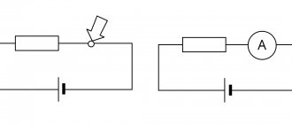
Current is measured with a device called an ammeter. There are four schemes for connecting an ammeter to a circuit. The first two (Fig. 3.7.1) are designed to measure direct current, and the second two circuits are designed to measure alternating current.
The second and fourth schemes are used in cases where the rated data of the ammeter is less than the measured current value. In this case, when determining the true value of the current, the conversion coefficient must be taken into account:
where Iist is the true current value, Imeas is the measured current value, kpr is the conversion coefficient. Voltage is measured with a voltmeter. Here, four different device connection schemes are also possible (Fig. 3.7.2).
These circuits also use methods to extend the voltage measurement limits (second and fourth circuits).
20) Measuring current transformers.
Current transformer
- a transformer, the primary winding of which is connected to a current source, and the secondary winding is closed to measuring or protective devices that have low internal resistance.
Instrument current transformer
- a transformer designed to convert current to a value convenient for measurement. The primary winding of the current transformer is connected in series to the circuit with the measured alternating current, and the measuring instruments are connected to the secondary winding. The current flowing through the secondary winding of a current transformer is proportional to the current flowing in its primary winding.
Current transformers are widely used for measuring electric current and in relay protection devices for electrical power systems, and therefore they are subject to high accuracy requirements. Current transformers provide measurement safety by isolating the measuring circuits from the high voltage primary circuit, often hundreds of kilovolts.
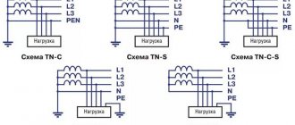
Connection diagrams for measuring current transformers
In three-phase networks with an isolated neutral (networks with a voltage of 6-10-35 kV), current transformers are often installed on only two phases (usually phases A and C). This is due to the absence of a neutral wire in 6-35 kV networks and information about the current in a phase with a missing current transformer can be easily obtained by measuring the current in two phases. In networks with a solidly grounded neutral (networks up to 1000V) or an effectively grounded neutral (networks with voltages of 110 kV and above), current transformers must be installed in all three phases.
In the case of installation in three phases, the secondary windings of the current transformers are connected according to the “Star” circuit (Fig. 1), in the case of two phases - “Partial star” (Fig. 2). For differential protection of power transformers with electromechanical relays, the transformers are connected according to the “Triangle” circuit (to protect the transformer winding connected in a star when connecting the protected transformer “triangle-star”, which is necessary to compensate for the phase shift of secondary currents in order to reduce the unbalance current). To save measuring elements in protection circuits, the “Current phase difference” circuit is sometimes used (should not be used for protection against short circuits behind power transformers with a delta-star connection).
Important parameters of current transformers are the transformation ratio and accuracy class.
Source
3.8. POWER MEASUREMENT
To measure DC power, simply measure voltage and current. The result is determined by the formula:
The ammeter and voltmeter method is also suitable for measuring total power, as well as active power of alternating current, if cosj = 1. Most often, power measurement is carried out by one device - a wattmeter. As mentioned earlier, the electrodynamic system is the best for measuring power. The wattmeter is equipped with two measuring elements in the form of two coils: serial and parallel. The first coil carries a current proportional to the load, and the second coil flows proportional to the network voltage. The angle of rotation of the moving part of the electrodynamic wattmeter is proportional to the product of current and voltage in the measuring coils:
In Fig. 3.8.1 shows a diagram of connecting a wattmeter to a single-phase network.
In three-phase networks, one, two and three wattmeters are used to measure power. If the load is symmetrical and connected as a star, then one wattmeter is sufficient (Fig. 3.8.2, a). If in the same circuit the load is asymmetrical in phases, then three wattmeters are used (Fig. 3.8.2, b). In the “triangle” connection of consumers, power is measured with two wattmeters (Fig. 3.8.2, c).
3.9. RESISTANCE MEASUREMENT
Electrical resistance in DC circuits can be determined indirectly using a voltmeter and ammeter. In this case:
You can use an ohmmeter - a direct reading device. There are two ohmmeter circuits: a) serial; b) parallel (Fig. 3.9.1).
The scale equation of the sequential pattern of intention is:
where r is the resistance of the galvanometer circuit. When the angle of rotation of the moving part of the device is determined by the value of the measured resistance Rx. Therefore, the instrument scale can be directly calibrated in Ohms. Key K is used to set the instrument needle to the zero position. Parallel type ohmmeters are more convenient to use for measuring small resistances. Resistance measurements can also be carried out with ratiometers. In Fig. 3.9.2 shows a schematic diagram of the ratiometer.
For this scheme we have:
Deviation of the moving part of the ratiometer:
Thus, the reading of the device does not depend on the voltage of the power source and is determined by the value of the measured resistance Rx.