Everyone knows power supply systems with voltages up to 1000 volts at the end-user level. They come in only two types:
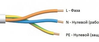
- three-phase (three phases and a working zero), where the voltage between phases is 380 volts, and between each phase and zero - 220 volts.
- single-phase (one of three phases from a common input to the facility, and a working zero), the voltage between each phase and zero is 220 volts.
But with security systems, the situation is much more complicated. To organize artificial grounding, GOST provides 5 systems: TN-C, TN-S, TN-CS, TT, IT.
Electrical Installation Rules (ELR) determine the conditions on the basis of which designers choose a grounding system for a facility. It is reflected in the design documentation and cannot be changed after the facility is put into operation.
In most cases, the TN grounding system is used, which requires mandatory grounding of the neutral of the power source. In this case, open current-carrying parts of final electrical installations can be connected to the neutral of the power source in various ways.
Each of the proposed artificial grounding systems has its own advantages and disadvantages. At the same time, any of them is aimed at solving issues of safe operation of electrical installations and the presence of people at the site.
Designations in grounding systems
The system designations use Latin letters:
- T (ground);
- N (neutral or functional zero);
- I (isolated);
- C (connection of protective and functional “zero”);
- S (separate application of protective and functional “zero” throughout the entire network).
In system designations, the first letter determines the type of grounding of the power source, the second letter indicates the type of grounding of the open components of the electrical receiver.
Properly designed and implemented grounding is one of the basic conditions for ensuring electrical safety of facilities where household or industrial electrical equipment is operated. When performing grounding, you must be guided by the requirements of the PUE (Electrical Installation Rules).
TN: grounding system with solidly grounded neutral
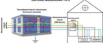
In this system, protection is carried out by connecting a solidly grounded neutral to non-insulated components of the electrical installation. In the TN grounding system, the conductor is PE, that is, the “zero” conductor. That is, when arranging it, housing screens and parts of electrical consumers that conduct current must be connected to a common “zero” - a conductor that is connected to the neutral.
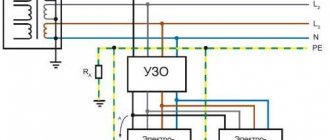
The functional “zero” in this case is designated by the letter “N”, and the combination of the “zero” functional and protective conductor is “PEN”. This grounding system has three subtypes TN-CS, TN-C and TN-S. The differences between them lie in the different ways of connecting the “PE” and “N” conductors.
This system does not use the method of neutral grounding using an arc suppression reactor, which in other types of systems is used as a compensating device.
Types of artificial grounding systems
The main document regulating the use of various grounding systems in Russia is the PUE (clause 1.7), developed in accordance with the principles, classification and methods of constructing grounding systems approved by a special protocol of the International Electrotechnical Commission (IEC). Abbreviated names of grounding systems are usually denoted by a combination of the first letters of the French words: “Terre” - earth, “Neuter” - neutral, “Isole” - isolate, as well as English: “combined” and “separated” - combined and separate.
- T - grounding.
- N - connection to neutral.
- I - isolation.
- C - combination of functions, connection of functional and protective neutral wires.
- S —separate use of functional and protective neutral wires throughout the entire network.
In the names of artificial grounding systems given below, the first letter can be used to judge the method of grounding the source of electrical energy (generator or transformer), and the second letter indicates the consumer. It is customary to distinguish between TN, TT and IT grounding systems. The first of which, in turn, is used in three different versions: TN-C, TN-S, TN-CS. To understand the differences and methods of constructing the listed grounding systems, each of them should be considered in more detail.
TN-C: system with working and protective “zero” in one conductor
The standard TN-C grounding system is a 4-wire current supply circuit with “zero” and three phase wires. This system involves combining zero working and protective conductors into one throughout its entire length. In other words, in TN-C the PEN conductor is common; it is used both for connecting current receivers and for “grounding” their cases (open conductive components).
“Grounding” the housing is necessary in case of damage to the insulation or a break in the phase wire, in which case it may short out to the housing. With this scheme, this will trigger the automation, which will turn off the voltage.
TN-C has some disadvantages. The most critical disadvantage of this grounding system is the lack of protection circuits in case of burnout or mechanical damage (break) of the “zero”. In such a situation, voltage is created on the housings of equipment and devices, which poses a threat to life. Another drawback is that it does not use a PE grounding conductor - that is, the sockets that are connected to it are not grounded, which leads to the need to ground any connected electrical equipment.
Important! Those who live in a house that uses a TN-C grounding system need to know that when forced to connect household appliances to zero in bathrooms, additional potential equalization lines cannot be used.
At the moment, TN-C is morally outdated. It is still used in private homes and buildings built in the early and mid-20th century. It can also be used where the risk is low - for example, in street lighting.
IT system
The IT system is intended for use in institutions where highly sensitive instruments can be used (laboratories, medical facilities).
The peculiarity of IT comes down to the fact that the neutral of the transformer substation is insulated in relation to the ground, or special instruments and devices with high resistance are used for grounding.
But open areas of electrical installations are grounded in the classical way - through a grounding loop.
The use of an IT system ensures minimal exposure to electromagnetic fields on sensitive equipment.
IMPORTANT TO KNOW: How to ground a washing machine.
TN-S: effective, but expensive
TN-S, in comparison with the TN-C grounding system, is a more modern, efficient and safe system in which the solidly grounded neutral of the transformer (or generator) is used to connect conductors with a “zero” on the side of the current source. When using it, the risk of high voltage occurring on the housings of electrical equipment is eliminated - even if the power line is damaged.
Meanwhile, there are two reasons why TN-S is not widely used in Russia. The first is that the Russian energy industry is mainly focused on 4-wire, 3-phase power supply circuits. The second reason is the high cost of using the TN-S grounding system.
During installation, when connecting three phases, you will need to use 5 wires to connect the equipment to the power source. For a single-phase connection, 3 wires are required. Due to the prevalence of 4-wire circuits for three phases in Russia, the use of TN-S will be inappropriate, since in this case it will be necessary to extend a separate line consisting of 5 wires from the transformer substation.
The new edition of the PUE, as well as GOST R50571, contains instructions for installing the TN-S system at facilities that require a high degree of electrical safety. Also, these regulatory documents prescribe its arrangement during construction and major repairs of buildings.
The essence of grounding
Why do you need grounding if everything works fine without it? Moreover, in normal operation no current flows through the protective ground wire at all.
The key word here is “protective”. Who does grounding protect and from what? It protects human bodies from the effects of electric current. And what it protects against is to ensure that dangerous voltage does not appear on the human body under any circumstances, and that current does not flow through the person.
Let's imagine the situation. There is some electrical appliance, for example an iron. The iron is connected through this plug.
Old plug without grounding pin
Older readers remember these very well; they were constantly unwinding, and attaching a flexible wire to them was a pain.
The body of the iron is partially metal. What happens if a phase suddenly gets on the body? In principle, nothing, the iron can even continue to work. But its body will be at a potential of 220V relative to ground. And since we all walk on the earth, if we touch the metal body of such an iron, current will flow through us.
And then - depending on your luck. If the skin and floor are dry, it will just tug a little...
But if the body of the iron is grounded, then when the phase wire hits the body, it will connect to the ground and go into the ground. In this case, an actual short circuit will occur and the circuit breaker of this line will be knocked out. And the body will remain as it was at zero potential.
In other words, if a phase suddenly gets onto the body of the device, this is no longer a human problem. This is a problem with the device itself and the circuit breaker, which must disconnect this device from the phase wire.
Why does the circuit breaker turn off? If the phase wire touches the protective (grounding) conductor, this is equivalent to a short circuit, that is, the maximum possible current in the circuit. And the machine will work due to electromagnetic protection.
Let me remind you that there is a time-current characteristic of the circuit breaker, and during a short circuit the circuit breaker will operate in the right zone of the characteristic, where the shutdown time tends to zero. Read more in my article about choosing a circuit breaker.
That is, the current in the protective grounding wire flows only at the moment of an accident, the rest of the time it is useless. Therefore, they used to save on it and use a two-wire power system, in which there is only zero and phase.
TN-CS: connection of a combined “PEN” with a solidly grounded neutral
TN-CS is a common grounding system that provides a higher level of electrical safety than TN-C while being less expensive than TN-S. The principle of this type of connection is to supply power using a combined “PEN”, which is connected to a solidly grounded neutral. Upon entering the building, it is divided into a protective zero (“PE”) and a conductor, which on the consumer side performs the function of “N”, that is, the working zero.
In accordance with the requirements of the PUE (clause 1.7.135), at the point where the working and protective zero are separated, busbars or clamps must be used for the connected conductors. The combined “PEN” must be connected to the bus or terminal of the protective zero “PE”.
According to clause 1.7.135 of the PUE, at the point where the PEN conductor is divided into the neutral protective (PE) and neutral working (N) conductors, it is necessary to provide separate clamps or busbars for the conductors, connected to each other. The PEN conductor of the supply line must be connected to the terminal or bus of the neutral protective conductor. In this case, the cross-section of the jumper located between the tires should not be less than the cross-section of the combined PEN.
Pros: the TN-CS grounding system is more reliable than TN-C: it eliminates the risk of a zero break, and the cost of its installation will be only slightly higher than for this outdated system.
Disadvantages: burnout or breakage of the PEN wire along the line from the facility to the substation leads to the formation of life-threatening voltage on the surface of electrical appliances. Because of this, when installing a TN-CS system, it is necessary to ensure reliable protection against damage to the combined PEN line.
About maintenance of electrical installations of residential buildings
However, at present, the system for servicing electrical installations of residential buildings is far from perfect. It does not create insurmountable obstacles to residents’ free access to electrical risers and electrical switchboards. This circumstance may be the reason for some negative impacts on the electrical installation of a residential building, which reduce the level of protection against electric shock and, therefore, reduce the benefits of using the first option compared to the second option.
When performing electrical installation work by residents who are ordinary people, the likelihood of erroneously connecting the terminals of any electrical equipment intended for connecting neutral conductors to the protective conductor of the electric riser, and the open conductive parts of class I electrical receivers to its neutral conductor, increases sharply. Similar errors can also appear when replacing existing electrical wiring in apartments and their incorrect connection to electrical risers, when the protective conductors of electrical wiring are mistakenly connected to the neutral conductors of electrical risers, and the neutral conductors of electrical wiring are mistakenly connected to their protective conductors.
Such errors are more likely in electrical installations of residential buildings, the electrical risers of which are made of conductors that do not have color and alphanumeric identification that meets the requirements of GOST 33542-2015. The likelihood of making errors increases even more in cases where conductors that do not have proper color identification are used when connecting any electrical equipment or electrical circuits to electrical risers.
The current situation is aggravated by the low qualifications of personnel operating electrical installations in residential buildings. When they carry out repair and maintenance work in the electrical installation of a residential building, it is possible to mistakenly connect the protective terminals of class I electrical equipment and even the electrical switchboard to the neutral conductor of the electric riser, and their neutral terminals to the protective conductor of the electric riser. That is, both the uncontrolled work of residents and the actions of unqualified operating personnel can lead to a decrease in the level of electrical safety.
TT grounding system: a new product in the Russian energy sector
This system implies “solid” grounding of the neutral of the power line. In this case, the grounding of open parts of the electrical installation capable of conducting current is carried out using a device that is “autonomous” from the solidly grounded neutral. With a 3-phase connection, the voltage is transmitted through 4 wires, in which the fourth represents “N”, that is, functional zero. A grounding conductor (most often modular-pin) is mounted on the consumer side. Then the protective zero conductors are connected to the grounding switch, which are connected to the housing components.
In the Russian Federation, the TT grounding system was approved relatively recently. It has become widespread in overhead power lines, which are used to supply electricity to rural areas, country houses, cottage villages and other suburban settlements. Another area of use of this system is power supply lines for temporary mobile trade facilities in urban environments.
TT has become a successful replacement for the TN-CS system, which in the specified area of application does not guarantee the reliability of the protection of the combined “PEN”.
When using this type of grounding, it is necessary to provide protection against lightning strikes. You also need to use special automation that provides protective shutdown. One more point - the PUE contains instructions on the use of the TT grounding system - supplying current to electrical installations with its use is practiced only when electrical safety cannot be ensured in the TN system.
Features of the TT system
The TT system is designed to provide grounding for buildings where it is impossible to create the necessary electrical safety conditions for the use of TN subsystems.
First of all, such a condition is the unreliability of overhead power lines and the absence of backup grounding on the supports.
TT is also used to ensure the safety of mobile buildings and buildings with conductive surfaces (kiosks, containers, trailers made of metal).
The peculiarity of this system is that grounding loops are used separately for the substation and the room, so there are no neutral conductors between them.
In addition, in this system no intersection is allowed between N and PE conductors. That is, each of them must have its own grounding circuit.
Thanks to such design solutions, it is possible to ensure insulation of conductive surfaces, as well as buildings, from a possible power line break.
Let us note that when organizing a TT, the use of residual current devices (RCDs) is required for all groups of power lines to provide protection against accidental contact with live parts of electrical appliances, as well as for safety in the event of a current leak in the house.
It has high safety ratings and is perfect for private homes, temporary buildings, etc.
The disadvantages of CT include the need for careful selection of protective circuit breakers and the correct calculation of their operating parameters.
In addition, there is a possibility of simultaneous failure of the RCD and phase breakdown on the body of the electrical device.
As a result, the entire PE conductor line and open conductive areas become energized.
IT: grounding system with isolated neutral "I"
The two main features of this system are the presence of a protective ground line (“T”) and an independent neutral “I”. When using IT, a minimum of wires are used to transfer current from the source to the consumer. In this case, it is necessary to ensure reliable connection to the grounding electrode of all components of electrical equipment housings capable of conducting current. Another nuance of the IT grounding system is the absence of a functional zero “N” on the current source-electric consumer line.
