What is a phase meter
A phase meter measures the level of phase shift in relation to two electrical oscillations that occur at a constant frequency. They can also recognize the angle in a circuit that consists of three phases.
- To start working, the device is connected to the required circuit. Then you need to make a connection to the voltage circuit. Additionally, you need to connect to the network that will need to be measured.
- If the line is three-phase, then the connection is installed on each phase. In order to measure the current, you need to connect a device in this line to each winding of the transformer.
- You can simplify your task by leaving the initial voltage connection to three phases, replacing in this case the original connection of the primary winding with a secondary one.
In simple terms, the device measures phase shift. The school curriculum said that changes in current and voltage are always represented by a sine wave graph. If everything is perfect, then they should match. But this is the material of how they teach at school, that is, it should be in theory. Practice usually shows otherwise.
User manual
Quite simple instructions for using a phase indicator suggest several types of device.
Let's look at the most popular samples:
- asynchronous motor brand I517M;
- lamp phase indicator;
- electronic phase indicator with multi-colored probes.
- Perhaps the most popular is the I517M asynchronous motor. The three-phase device accurately indicates the correct phase connection using the hand on the clock. If the indicator disk rotates in its direction (and this is determined using an additionally applied contrast-type mark), then the alternation order has been set correctly. By the way, the terminals for the device are the stator winding terminals. If the phase order was violated, the direction of rotation will be reversed. If one of the phases is disconnected, the rotation of the disk will stop.
Another popular phase indicator is a device with a conventional incandescent lamp as a base.
However, no one limits the use of modern LEDs or neon bulbs. They can also be used in construction, since they are only signaling devices. Their connection is made through capacitors, which determines the efficiency of use of the device. True, you still need to know exactly where the resistor is located. Because the resistance of the circuits will differ depending on the connection to a capacitor or resistor. If in the first case there is a brighter illumination, then the intensity of the glow in the second may be weak or completely absent. Thanks to this simple principle, the phase sequence on the motor is determined. However, there are more complex devices. They often use an electronic principle of operation, which assumes the presence of a graphical technique. However, you can assemble it yourself. To analyze the voltages, the phase currents of the components on three asymmetrical type branches are studied. The different loads on the phases are capacitive or active in nature. Correct phase connection should be characterized by a threefold voltage difference on different branches (of course, if the sequential order was observed). With a load of 60 Volts across the resistor, the neon lamp will give a light signal. This way the correct phasing will be determined. Attention! This operating principle is key for the “tube” phase indicator circuit. . If the locations of the desired phases on the branches change, the load on the resistor inevitably decreases
And even with a slight voltage drop, the neon light will not light up. There just isn't enough nutrition. And based on this sign, we can safely conclude that the phasing is incorrect. When engine operation will imply a change in rotor rotation due to the reverse mechanism.
If the locations of the desired phases on the branches change, the load on the resistor inevitably decreases. And even with a slight voltage drop, the neon light will not light up. There just isn't enough nutrition. And based on this sign, we can safely conclude that the phasing is incorrect. When engine operation will imply a change in rotor rotation due to the reverse mechanism.
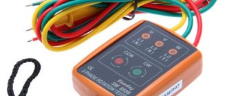
As a rule, a phase indicator consists of a housing and a gallant trio of probes. The latter are often marked with a color or some symbolic letter. In the case of multi-colored markings, the colors usually used are red, yellow and green. These probes allow you to get a light or sound reaction to connection to phase-type conductors. For example, in the case of continuous sound, we should talk about incorrect phasing. Conversely, an intermittent sound indicates that the engine is operating correctly. Sometimes devices have a special button. But not everyone can boast about it.
What types of phase meters are there?
There are only two types of phase meters. One of them is digital, and the second is electrodynamic. They work almost identically.
But it is believed that digital ones are still inferior in accuracy to another type. Moreover, they can clearly see all the changes that occur in the network.
There is also professional equipment that is used exclusively in laboratories.
- It is usually intended for electrical installations that require repair.
- The principle of their operation is the same as those that are widely used for domestic needs.
- If you need to adjust some electrical equipment, it is better to resort to an electrodynamic phase meter.
- They are often placed in a universal device that can be used in any area.
Panel devices are also used precisely. Often they are simply collected into one scheme and used as a single whole, used to measure certain indicators. It’s convenient that you can assemble such a device for yourself. Then it will meet certain requirements.
Necessity of application
There are situations during which the connection of a three-phase network must be carried out in phase rotation order. The fact is that the direction in which the rotor rotates when connecting an asynchronous motor to the network cannot be accurately indicated unless we strictly follow the phasing procedure.
For example, when it comes to operating a fan for the corresponding system or a drive for operating a pump, it is necessary to clearly know the direction of rotation. This ensures the execution of the technological cycle. Therefore, it is important to maintain consistent connections in this case. In order to solve this problem, you should resort to using a special device called a phase indicator. This allows you to understand why it is needed. The scope of application of the phase indicator is quite wide and is constantly growing.
If the phasing is set correctly, then the order of the phases goes from A to B and ends with C. The same order determines the direction of rotation of the engine. For example, if the wires that power the windings are connected in the correct order, then the motor rotor operates conditionally in a clockwise direction. However, in a situation where two of these phases are changed, the direction of rotation of the rotor will be disrupted. Then the technological process in which the engine is involved will simply be disrupted. This will cause the equipment used in the drive to be damaged and fail. After this, if you perform the reverse procedure with the phases, the engine operating order will return to normal and the process will be correct.
Electrodynamic type
The design of this type of phase meter assumes a simple ratiometric circuit. It accurately detects movement. The device has two tightly connected frames that form an angle of 60 degrees. They are attached to the axis, and they are already fixed to the nodes. Thus, there is no mechanical resistance.
- The device is equipped with a mechanism that can rotate through the angle at which the phases move. It is also equipped with a linear scale, on which the deviation value is recorded.
- One current coil of the device is fixed, while the other two remain movable. Current passes through these moving elements, so an electromagnetic flux is formed between all elements.
- When magnetic fluxes touch each other, torques are generated. Their size is equal to the distance between the elements of the invention. By the amount of current in the moving coil, you can determine the amount of rotating torque.
- This can also be determined by the current in a static coil. Also, these parameters depend on the characteristics of the device and on the indicator by how much the phase angle shifts.
The moving element will rotate until the rotating moments become equal.
As already mentioned, the advantages of such a device include its accuracy and low cost. But there are also disadvantages - high power consumption and indicators that depend on frequency parameters.
Popular models on the market
The most popular phase meters are devices of the D5721 and D5782 brands.
This type is used in single-phase current-carrying networks, the frequency of which is 50-60 Hertz. Weight more than 6.5 kg. Performs measurements of voltage and current phase displacement.
Megeon 40850 has small dimensions. The measurement process takes place in a fairly short time, while its accuracy is high. This device is equipped with LEDs, alligator clips, and a built-in buzzer.
The invention weighs 810 grams, second class safety. It is capable of operating at air temperatures from -10 to +40 degrees, and takes measurements in electrical equipment under voltage from 200-400 volts.
Ts302 takes measurements in a three-phase line, and the current frequency can vary from 50 to 10,000 Hertz. This type easily tolerates vibration.
Digital type phase meter
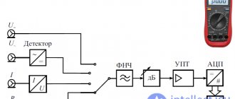
In the photo of the phase meter it is noticeable that digital devices may differ from each other. It depends on the principle used in their manufacture. Some of them can be manually controlled and still produce very accurate results.
- The principle of their operation is this: when a measurement is taken, a pair appears, which can be represented as a sine wave.
- It affects the phase shifter, and it is already under the control of the desired mechanism.
- The indicators are measured until the phases coincide. If this is adjusted, the phase shift is monitored by a phase-sensitive device.
The detector sends a signal to the guiding mechanism. Data can be obtained when the parameters match.
This device has its advantages - it is easier and more convenient to use. But this, in turn, determines its high cost.
Necessity of application
So, the need for phase rotation arises when working with a three-phase electrical network. Without strict phasing, there will be no guarantee that the direction of rotation of the rotor of an asynchronous motor will be correct. And without a clear direction, it is impossible to implement a specific technological cycle. This is precisely the problem that a phase indicator should solve.
Attention! Moreover, the scope of application of the device can be any, since the technological development of electrical networks does not stand still. It can be used both in the operation of ventilation systems and to ensure the operation of any pumps
With correct phasing, the sequential order will ensure the rotor moves in the given direction (for example, clockwise). To do this, the wires must be connected in a certain way. If the sequence of their connection is changed, then the rotation of the rotor will simply be disrupted. And then the entire technological process will be at risk. Up to and including the destruction of all equipment. However, when the correct phase sequence is restored, its operation should resume.
How to use a phase meter
Instructions for using the phase meter are included in the box for each device. Be sure to check if your operating conditions match those recommended by the manufacturer. Also make sure that the range matches the metrological characteristics. Only after these conditions are met can the circuit be assembled.
Several stages of use:
- Read the instructions carefully. The manufacturer indicates in it not only the principles and methods of operation, but also some nuances that will help in the future;
- The arrow of the device must be set to 0. Use a corrector for this;
- Look at the position of the buttons to make sure they are off;
- Now you can connect probes to the required connectors;
- Turn on the device. The power light should light up;
- Now you should wait a while, about 15 minutes, for the phase meter to warm up before work. Do not ignore this step, it will affect the accuracy of the indicators;
- Record the voltage;
- Now you should press the buttons in accordance with the selected voltage. The frequency range is set according to the same principle;
- Next, the input with 4 poles is used;
- Set 20 by switch;
- Now you can set the device to 0. Use the regulator for this.
How to choose
Before you buy it, think about how and where you will use it. Will it be a stationary home use or will it require more power on a production site.
- For your home, you can buy an inexpensive analog version, but if we are talking about an enterprise or production, you don’t have to save money and buy a digital version.
- The internal structure will also affect the price. This can be either the most common type or a modern one with many applications and built-in functions.
Pay attention to the dimensions too. If you need to measure phases in different places, it is better to buy a small device that is easy to carry. Highly qualified specialists can purchase a large and multifunctional device.
Undoubtedly, brand awareness will also affect the price. It is important to consider the price-quality ratio and find a middle ground for yourself.
Photos of the best phase meters
Share with friends