Home » Electrical installation » Electrician's tools » What is a phase meter?
A phase meter is a special device that belongs to the electrical measuring series. Its function is to measure the phase angle relative to a pair of electrical oscillations with a constant frequency.
What is a phase meter?
Using this device, you will have a wonderful opportunity to determine the angle that shows the phase shift in a three-phase voltage network. This is precisely its main area of use. In this article we will talk about the device and operating principle of the phase meter. You will also learn the rules for its use.
What is a zero sequence
In order to understand how TZNP works, you first need to remember what a three-phase network is. A three-phase network is an alternating sinusoidal current network. In a three-phase circuit, the phases are shifted relative to each other by 120 degrees. This is what it looks like on the graph:
Interesting!
The basic ideas and provisions of three-phase power supply networks were developed by Mikhail Osipovich Dolivo-Dobrovolsky. He developed a three-phase asynchronous motor with a short-circuit rotor of the squirrel cage type, with a wound rotor and a starting rheostat, a spark arrester grid, a phase meter, and a dial frequency meter.
If you depict this on a vector diagram, the image will resemble a three-pointed star. Provided that the currents and voltages between the phases are equal, such a system will be called symmetrical. The geometric sum of these vectors is zero.
Important! There are direct and reverse phase sequences. The phases are designated by the letters A, B and C
Then the sequence ABC is forward, CBA is reverse. In this case, the phase shift angle in both cases is 120 degrees. With a zero sequence, the vectors of all phases are directed in the same direction; accordingly, the resulting vector is significantly higher than that (3 times compared to the zero sequence) in the normal state of the system.
In the event of an interphase fault, the currents in all phases will increase, but the system will still remain symmetrical. And zero sequence voltages and currents are equal to zero, as in the normal state of the circuit.
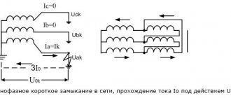
As a result of a single-phase ground fault, the system will become asymmetrical and zero-sequence currents I0 and U0 will be observed. Suppose phase C is closed, then the currents of phases A and B will rush to zero, and in phase C to a third of Is.
Then:
I0=1/3(Ik+0+0)
Hence Ik=I0*3. These currents arise under the influence of short-circuit voltage or Uk0 between the terminal of the transformer or generator winding and the point at which the short circuit occurred.
Phase indicator
Author: admin, 05 Feb 2015
In this article we will look at the operation and diagrams of phase indicators, I will also tell you how to make a simple phase indicator with your own hands, why you need a phase indicator, how to use it and types of phase indicators.
Phase indicators are devices designed to determine the order of phase alternation
Please note - it is the order of alternation, i.e. not a single phase indicator will show you where phase A, B and C are, it will only show direct (A-B-C, B-C-A, C-A-B) or reverse (A-C-B, C-B -A, B-A-C) phase alternation. But in most cases this is enough, for example, if you connect a new input to the electrical panel and do the same alternation as the old input, then all the electric motors will rotate in the right direction
For phasing, for example, transformers, you will need to check the phases of the same name with a simple two-pole indicator. On ones with different names it will glow, on ones with the same name it won’t. But let's return to the phase indicators.
The industry produces a large number of different models of phase indicators, the most common brands were FU-2, EI5001 (analogous to I517m), VC-805... Instructions for using phase indicators EI5001 and VC-805 can be downloaded on the regulatory documents page.
Let's look at the FU-2 phase indicator shown in the picture above. The phase indicator has three terminals designated according to the phases “A”, “B” and “C”. Three alligator clips, or three probes, are connected to these clips; for convenience, electricians mark them with colored electrical tape in accordance with the color marking of the phases according to the PUE. (A - yellow, B - green, C - red).
They use the FU-2 phase indicator as follows : connect the “crocodiles” to the busbars or exposed phase wires, after which they briefly press the button located on the left side of the housing. If the white disk with slots rotates in the direction indicated by the arrow next to the disk (clockwise), then the order of phase alternation is direct. If the disk rotates against the arrow, then the phase sequence is reversed.
If you don’t have a phase indicator on hand, you can make a simple phase indicator with your own hands. To do this, we need 4 incandescent lamps of 220V, 25-60 W, sockets for them and a non-polar capacitor with a capacity of 2-3 μF.
Circuit of the simplest phase indicator
The diagram shows:
- L1-L4 - incandescent lamps 220V, 25-60 W.
- C1 - non-polar capacitor 2-3 µF, 500V.
- A, B, C - probes corresponding to phases A, B, C.
Circuit operation
If, when the probes touch the phases, the lamps of phase “A” (L1, L2) light up at full incandescence, and the lamps of phase “B” (L2, L3) light up at half-incandescence, then the order of phase alternation is direct.
Scheme at work
Of course, such a phase indicator turns out to be quite bulky and inconvenient, so let’s consider another phase indicator circuit, somewhat more complicated, but much smaller.
It is possible, in principle, to modify this phase indicator by replacing the chains of lamps with chains of a series-connected quenching resistor and a light bulb from a flashlight, or by adapting LEDs.
Phase indicator circuit on a thyristor
phase indicator on a thyristor
The diagram shows:
- R1 - resistor C5-35(PEV) 5 W, 1.8 kOhm.
- R2 - MLT-1 resistor, 10 kOhm.
- D1 - diode KD105V.
- VS1 - thyristor KU202N.
- L1 - lamp МН26-0.12.
Circuit details
Resistors can be of any brand with a value close to the specified one. R1 for a power dissipation of at least 5 W (depending on the lamp used), R2 for a power of at least 1 W.
Diode D1 can be taken from brand KD209.
The thyristor can be replaced with T112-10-5, T112-25-10.
Circuit operation
Terminal “0” is connected to zero, Terminals “A” and “B” are connected to any two phases. If the light bulb glows brightly, it means the terminals are connected to the same phases “A” and “B”, but if the light bulb lights up dimly or does not light up at all (can be adjusted by selecting the value of R1), then the terminals are connected in reverse.
Without going into details, I will say that such operation of the circuit is due to different opening angles of the thyristor; if you are interested, you can “rummage” on the Internet.
It will be interesting to read:
Battery charger
Installation of a pass-through switch
Sockets in series
Categories:
Screwdrivers
Another type of dielectric tool up to 1000 V are screwdrivers with different blade options.
More modern models are marked PZ; the previous generation of screwdrivers was marked PH. The difference between PZ is that the tip has additional guides (we are talking about a cross slot).
The handles are made of high quality plastic and are also coated with a protective substance.
A number of manufacturers produce more advanced screwdrivers. They are equipped with a current indicator. Contact with a phase in the electrical circuit immediately makes itself known by the fact that the indicator on the product lights up.
In addition to its main functions, such products also perform informative functions.
Kinds
All phase meters according to the operating principle are divided into three types:
- Electrodynamic;
- Digital;
- Electromechanical.
The first two types are in greatest demand, but it is recommended to use digital devices. They are characterized by greater accuracy and low noise levels.
According to the number of phases, phase meters are:
- Single-phase - for carrying out measurements in a 1-phase circuit.
- Three-phase - for 3-phase circuits.
Electrodynamic
Until recently, electrodynamic (electromagnetic) phase meters were in greatest demand. Structurally, this device consists of a simple ratiometric mechanism that allows accurate measurement of phase displacement.
The device has two frames that are rigidly connected to each other. The angle between the mentioned elements is 60 degrees. The frames are mounted on axes fixed to support units. Thanks to this feature, the device has no mechanical resistance.
The device has a special element that rotates through an angle that characterizes the magnitude of the current phase shift. Using a linear scale, the technician can record the measurement and determine the current offset setting.
The electrodynamic phase meter is based on a fixed current coil, as well as two more similar, but movable elements. The displacing coils have their own currents flowing, which contributes to the appearance of a magnetic flux in all coils - moving and stationary.
When the coil flows interact, a pair of rotating moments appears, the magnitude of which depends on the distance between the moving elements of the device. The mentioned moments have different directions, which are opposite in magnitude.
POPULAR WITH READERS: How to find out the level of illumination in rooms
The torque indicators depend on the currents flowing in the moving coils, as well as on the current level in the fixed coil. In addition, the mentioned indicators depend on the design features of the coil and the angular phase shift.
As a result, the moving element of the phase meter rotates under the influence of the mentioned moments until a situation where equilibrium does not arise, that is, the moments become equal.
The phase meter itself often has a gradation that allows you to accurately measure the power factor.
The advantages of the device are reliability, high accuracy of readings, and affordable price.
The disadvantage is the dependence of the measured parameters on the frequency indicator. Another disadvantage is the increased power consumption from the source being studied.
Digital
As noted, this is the preferred type of device due to its more convenient use and high accuracy. Such devices are manufactured using various technologies.
For example, a compensation phase meter makes the most accurate measurements, despite the need for manual use. The device operates on a different principle. During the measurement process, a pair of U appears, having a sinusoidal type, and the main purpose of the device is precisely to calculate the shift between phases.
First, U is fed to a phase shifter, which is controlled from a special device. The measurement process occurs smoothly until the phases coincide. During the setup process, the phase shift value is calculated using a phase-sensitive device.
The output signal is transmitted from the detector to the control device. The given algorithm is implemented by encoding pulses. Once balancing occurs, the phase shifter code reflects the information of interest.
At the present stage, digital phase meters use a technique that is based on discrete counting. The essence of the method is to go through two stages.
First, a process will be carried out to convert the phase offset into a signal parameter with a certain duration. Next, the length of this pulse is changed using discrete counting.
The device includes:
- Converter that converts phase displacement into pulse;
- Time selector;
- An element that generates discrete pulses;
- Control device and counter.
The advantages of digital type phase meters are lower error due to calculations performed over several periods, greater accuracy and ease of use. Disadvantages - higher price.
User manual
To understand the use of the phase meter, the main attention is paid to the operating instructions (included with the device). There are a few steps you need to take before you begin.
First, you should make sure that the operating conditions correspond to those recommended by the manufacturer, and the frequency range is in accordance with the metrological characteristics. After this, the circuit itself is assembled.
The phase meter is operated according to the following algorithm:
- First you need to read the instructions that come with the product. The document reveals the nuances and rules for using the device.
- Using the corrector, the arrow is set at the 0 mark.
- Make sure the buttons are not actuated.
- Connect the input probes to the required connectors.
- Press the key that supplies power to the device. Pay attention to the lighting of a special indicator.
- Wait a while for the device to warm up well. This is necessary to achieve maximum measurement accuracy. On average, the exposure time should be about 10-15 minutes.
- Find the input voltage.
- Press the button depending on the choice of external voltage and set the required frequency range.
- Press “>0<” for a pair of channels and “+”.
- Connect the channel probes to the 4-pole input.
- Set the limit switch to position “20”.
- Then move the meter needle to the “zero” position using the regulator.
What is the source of negative and zero sequence currents?
Zero sequence current is:
The sum of the instantaneous values of the currents of the three phases of a three-phase system The zero-sequence system differs significantly from the direct and reverse ones in that there is no phase shift. The zero current system essentially represents three single-phase currents, for which the three wires of the three-phase circuit represent the forward wire, and the return wire is the ground or the fourth (zero), through which the current returns.
Negative sequence components (current, voltage) arise when any asymmetry appears in the network (phase loss, inclusion of an asymmetric load, single-phase or two-phase short circuit). Zero sequence components appear when one or two phases are broken, single-phase or two-phase short circuit to ground. (for phase-to-phase faults without ground, the components are equal to zero) Negative sequence current, as is known from, appears during any asymmetrical short circuit, and briefly during a three-phase short circuit. The zero sequence current is used to increase the sensitivity of starting the RF transmitter during a short circuit to ground, and the starting relay of the phase current of the spacecraft is used for symmetrical short circuits
In practice, the zero-sequence current is obtained by connecting the secondary windings of current transformers into a zero-sequence current filter (Fig. 7.11). From the diagram it can be seen that the current in the KA relay is equal to the geometric sum of the currents of the three phases: The current in the relay appears only during a single-phase or two-phase short circuit to ground. Short circuits between phases are symmetrical systems, and accordingly, the current in the relay Ip = 0.
ZOH phase current is when phases a, b, c are 120 degrees apart from each other. When three phases are turned in one direction - zero sequence current. This occurs during single-phase ground faults in networks with a grounded neutral. Therefore, TZNP - zero-sequence current protection is used to protect against ground faults - a zero-sequence current has appeared, which means there is a ground fault, the protection is triggered. . Negative sequence currents are when the phase sequence is disrupted. They occur during interphase short circuits; for protection I use TZOP - negative sequence current protection. That's it in a nutshell. Negative sequence components (current, voltage) arise when any asymmetry appears in the network (phase loss, inclusion of an asymmetric load, single-phase or two-phase short circuit).
Zero sequence components appear when one or two phases are broken, single-phase or two-phase short circuit to ground. (for phase-to-phase faults without earth, the components are zero) Zero sequence currents are essentially a single-phase current, branched between three phases and returning through the earth and circuits parallel to it. Because of this, the circulation path of zero-sequence currents is sharply different from the path along which positive or negative sequence currents pass. For the practical implementation of the method of symmetrical components, it is necessary to construct three equivalent circuits: direct, negative and zero sequence. The configuration of these circuits and the parameters of their elements are generally not the same.
The positive sequence diagram is the same as for calculating the three-phase fault current. From this circuit, the resulting EMF and the resulting positive sequence resistance are found: and . The beginning of this circuit is the point of zero potential of the power sources, the end is the location of the short circuit to which positive sequence voltage is applied. Negative sequence components occur when any asymmetry appears in the network: single-phase or two-phase short circuit, phase loss, load unbalance.
Zero-sequence components occur during ground faults (single- and two-phase) or when one or two phases are broken. In the case of a phase-to-phase fault, the zero sequence components (currents and voltages) are equal to zero.
This method is used by many relay protection and automation devices. In particular, the operating principle of a zero-sequence current transformer is based on the addition of current values in all three phases of the protected area. In normal (symmetrical) mode, the sum of the phase current values is zero. In the event of a single-phase fault, zero-sequence currents will appear in the network and the sum of the current values in the three phases will be different from zero, which will be recorded by a measuring device (for example, an ammeter) connected to the secondary winding of the zero-sequence current transformer.
For three-phase transposed power lines, the result of this transformation is the exact matrix of eigenvectors (modal transformation matrix). It is the same for both current and voltage.
Main technical characteristics of a digital phase meter
1) operating frequency range 0.002…2000, kHz;
2) input voltage range 0.002…2, V;
- How to check the voltage with a multimeter in the network: measuring the voltage in a 220 volt outlet
3) phase difference measurement limits ±180°; 0…360°.
4) the main error in measuring the phase difference (with relative instability of the signal frequency of no more than 10–4 per 10 minutes), where j is the measured phase difference in degrees; A
– ratio of input voltages, dB.
5) the input resistance of the device is more than 1 MOhm, the input capacitance is 30 pF.
Operating principle. In the F2-16 phase meter, the measured phase shift is converted into a time interval (Fig. 3.4, a
and b
). With the help of forming devices (FU), short-term pulses are generated from the voltages under study at the moments when the voltages pass through 0 V
Rice. 3.4. Block diagram and timing diagrams of a phase meter with conversion of the phase shift into a time interval
side of increase. These pulses arrive at the inputs S
and R
trigger T, and rectangular pulses are formed at its output. The duration of the trigger pulses t is proportional to the measured phase shift: . The average voltage at the trigger output, proportional to the measured phase shift
,
measured by a built-in digital DC voltmeter. In this case, the pulse amplitude is selected in such a way that the voltmeter readings numerically coincide with the phase shift, expressed in degrees.
With this method of measuring the phase shift, a systematic error may arise due to the asymmetrical limitation of the voltages under study in the FU. In this case, the voltage at the output of the limiter, for example in FU1, will have a constant component (Fig. 3.4, c
). The differentiating circuit included in the FU does not allow a constant component to pass through, therefore the moments when the voltage passes through zero are shifted (shown in Fig. 3.4, c
arrows). Changing the t interval leads to an error in measuring the phase shift.
Structural scheme. The F2-16 phase meter is made according to a two-channel scheme; the reference channel (OC) and the measuring channel (IC) are identical (Fig. 3.5). To eliminate the error due to asymmetrical limitation, the phase meter uses two triggers. The limiter amplifiers are made according to a push-pull circuit, so their output voltages u
3,u
4 and
u
5,
u
6 are antiphase (Fig. 3.6).
Rice. 3.5. Block diagram of phase meter F2-16
The role of differentiating chains is performed by level discriminators. Discriminators OK are triggered when voltage u
3,u
4 in the direction of increase, and the IR discriminators are triggered when voltages
u
5,
u
6 pass through 0 in the direction of decrease.
Trigger T2 is switched by a positive pulse u
7 and a negative pulse
u
9. Trigger T2 is switched by pulses
u
8 and
u
10, respectively, which are shifted by half a period relative to
u
7 and
u
9. Rectangular pulses
u
11 and
u
12 with an amplitude of 6 V with T1 and T2 are added in the adder, forming
u
13. A bias voltage of 12 V is also supplied there. A direct current amplifier (DCA) separates the DC component and changes its polarity, after which the voltage is measured by a digital voltmeter.
If in the first channel, for example, the limitation is asymmetrical, then the pulses u
7 and
u
8 are shifted, as shown by the arrows in Fig.
3.6. u
pulse will become shorter, and the
u
12 pulse will become longer, so the resulting constant component will remain unchanged.
Rice. 3.6. Timing diagrams explaining the operation of the F2-16 phase meter
The F2-16 phase meter has a phase shift measurement mode of ±180°. In this mode, using the voltage switch u
7 and u
8 are swapped, the adder is supplied with a bias voltage of not –12, but –6 V. Voltage graphs for this mode are shown in Fig. 3.6 on the right.
Electromagnetic
It is used only in electrical circuits with direct current and includes components such as a magnetic conductor element, a control type winding, and a short-circuited turn.
The delay in switching is created due to the short-circuited winding. It contains one turn, which is fixed on the core component of the magnetic circuit. This turn has the appearance of a sleeve. It is made from metal - aluminum or copper.
To provide a delay interval for operation, an auxiliary magnetic flux is provided. Adjustment is possible by changing the gap parameters or the tension of the return spring. Adjustable within 5 s.
The relay is common in circuits that control the acceleration or braking of an electric drive. The time delay is affected by temperature. If the winding temperature deviates by 10°C, then the delay changes by 4%.
How to make it yourself
Next, we will briefly tell you how to make a generator with your own hands, which can be used in natural conditions or in de-energized places.
Of course, the power of these devices cannot be compared with a radioisotope specimen, but due to the difficult availability of plutonium and its harmful qualities for the human body, one has to rejoice at this.
A thermoelectric element will be required. It is better to use them not in a single copy, connecting them in parallel, this will increase the power.
Using one element, the power may not be enough to charge even the simplest gadget.
You will also need a metal case, for example, a used and no longer needed power supply from a personal computer, and a processor cooling element.
Proven brands
The first company on the list has been working for the second decade in the research, design and production of dielectric tools capable of protecting workers from voltages up to 1000 V.
The plant provides a guarantee for its products. The ROST company has achieved success not only due to the quality of the products supplied, but also for the warranty and post-warranty service of its products.
STOK is working on creating a specialized tool for cutting wires, cables, and removing insulating layers from them. The company produces sets of tools for a wide range of purposes.
Why might a breakdown occur?
During the constant operation of an electric motor, a lot of unforeseen circumstances can occur that will disable it. And in order to be prepared for all these difficulties, you need to know them and be able to prevent them.
Here's what can damage an electric motor:
- Low voltage in the electrical network.
- The voltage is too high for which the motor is not designed.
- Poor power supply and poor signal quality.
- Constant jumps in the system.
- Incorrect installation or non-standard operating rules of the electric motor.
- Increased temperature in a running engine and frequent overheating.
- Poor cooling of equipment.
- Increased temperature in the space around the engine.
- Low atmospheric pressure due to engine operation in mountainous areas.
- Problems with the engine fluid.
- Frequent turning on and off of the engine.
- Increased inertial load on the engine. This indicator is different for each model.
- Overheating due to blocked rotor or phase loss.
We will consider the simplest and most popular device for this further.
Power factor control
How it works in practice. If you see that the cosine index is close to one, you should understand that the ratio of energy that is consumed is used as accurately as possible for useful work. If the arrow goes to the left, electricity begins to be spent on useless heating of devices connected to the network, such as electric motors, windings of various transformers, or simple cable lines. This is accompanied by a decrease in network voltage, which entails an increase in power consumption by all equipment to ensure standard useful operation.
We figured out what a phase meter is, as well as how it works and what it shows. Acceptable values of the device will be coefficients in the range of 1-0.95, with a deviation towards inductance, to the right. But, if the value turns into inductance, then how to compensate for this?
This is not a problem, since at all electrical substations special batteries of capacitors are installed, which compensate for the so-called reactive power. Just from the description it is not difficult to understand what such devices do. They equalize and compensate for the inductance present in the network, which creates negative resistance, and therefore level the angle formed between the voltage and current axes, which will later be demonstrated by a device such as a phase meter.
This approach also has its downsides. If such capacitors have a constant capacitance, this leads to problems that arise when connecting to the network for users who have a small level of inductive reactance. In this case, the power ratio changes.
In such a scenario, compensation becomes not only ineffective, but also harmful in places. The principle of operation of the phase meter is to detect such problems. If not necessary, compensation installations are designed in such a way that they can operate in automatic mode and, if not necessary, do not interfere with the electrical network.
This is controlled by special machines that turn on the installation only at a certain value of the cosine of the angle. This happens by changing the battery capacity, thereby adjusting the desired level of current and voltage ratio in the network. Such installations are very powerful and operate under a voltage of several thousand volts.
Automatic systems are usually installed in large enterprises where there is a significant consumption of electricity due to a huge number of high-power devices. In local substations, which are located in residential areas of the city and in rural areas, the installation capacity is calculated during installation, after which it does not change.
Types of phase meters
As when choosing any other device, here the buyer is faced with a simple question - which phase meter is better to choose?
Phase meters that operate on the panel principle can be of two modifications - equipped with a pointer interface, or a more modern digital one. There are no differences in the quality of work between them, but switches are more common among specialized personnel who work with electricity, since they more clearly demonstrate changes in the network.
There are also phase meters that are used only in laboratories. They are more often used in desktop installations, electronic devices and devices in need of repair. The principle of their operation is absolutely identical to conventional phase meters.
The current standard for complex electrical equipment used for overlays is that all measuring instruments are available in the version with dials. Moreover, most often they are part of some kind of universal device that finds many areas of application.
The same thing happens with panel devices, the creation of which also uses the principle of universality. Many of them are also combined into one multitasking device that can simultaneously work with many quantities, which is determined by the mode of use and the needs of the user.
Synchronous generators
Personnel who are allowed to work with synchronous generators do not need instructions for using the phase meter, since they are qualified electricians. Such people know that the power of a synchronous generator is directly proportional to the power of the rotor, in particular to the level of current that is excited in it.
During their work, specialists must monitor and constantly monitor changes in the value of the cosine of the angle, which is shown by the phase meter. Based on this value, adjust the current level inside the circuit. Usually, during normal operation, an automatic system is responsible for all this, which regulates the required values.
But a specialist is needed during emergency situations, such as starting a generator for operation, or during its failure, when you need to reboot and start it manually. For this purpose, a generator panel is used, in which a phase meter is mounted.
In this case, you do not need to know how to correctly connect the phase meter, since it is already connected to the circuit. It constantly monitors changes in the network, and when the arrow moves to the right, a warning is triggered, because in such a situation, significant overheating of the generator and its stator winding can occur.
- How to properly connect a duct fan
- Details about TML tips
In which industries is a soldering iron used?
If the arrow points to the right and the load switches to capacitive, the alarm also triggers. This is because in this mode the generator begins to independently consume energy from the network, and this is already an emergency situation in operating mode.
APPLICATION OF ELECTROMAGNETIC RELAYS
Perhaps, relays operating using the electromagnetic principle are most widely used in the field of distribution and production of electrical energy.
Relay protection of high-voltage lines ensures trouble-free operation of substations and other connected equipment.
The control elements used in relay protection installations are designed for connection switching at operating voltages reaching several hundred thousand volts. The widespread use of relay protection for high-voltage lines is due to:
- high durability of relay elements;
- quick response to changes in parameters of connected lines;
- ability to work in conditions of high intensity electromagnetic fields and insensitivity to the appearance of parasitic electrical potentials.
Also, through relay protection installations, power lines are backed up and damaged sections of the power network are immediately taken out of service, for example, when a line is shorted to ground or live parts are broken. To date, more reliable means of protecting power lines than relay protection have not yet been invented.
In addition, currently the electromagnetic type of relay is widely used in control systems for production and conveyor lines. Most often, this type of control systems is used in industries with high parasitic potentials making it impossible to use semiconductor control systems.
For example, there is a known case when, during the modernization of conveyor line control systems at one of the elevators, new equipment built with the latest semiconductor elements constantly failed.
As it later turned out, the cause of the breakdown was static electricity that occurs when grain moves along the conveyor belt, and since the potential equalization system was not provided in these premises, the question arose about moving the control panel to a protected room.
This was associated with enormous material costs. As a result, it was decided to switch to relay control units that are insensitive to static voltage.
The operating principles underlying the functioning of electromagnetic relays are used in remote load control devices - starters or contactors.
The principle of operation of these devices is in many ways similar to the operation of relays, with the only difference being that these devices are designed for switching power circuits, the current strength in which can reach 1000 A, and in the case of particularly powerful installations, even higher.
In addition to low-voltage equipment, relay units are used to control capacitor units, which are used for smooth starting of high-power electric motors.
But the most significant application of electromagnetic type relays is their use in the first electronic computers, as logical elements capable of performing the simplest logical operations. Despite the low performance, these first computers were superior in reliability to the next generation of tube-based computer systems.
The simplest examples of using an electromagnetic relay in everyday life are control relays in various types of household appliances: refrigerators, washing machines, etc.
2012-2020 All rights reserved.
The materials presented on the site are for informational purposes only and cannot be used as guidelines or regulatory documents.
Phase meter
These instruments for measuring various parameters of electricity are used both for scientific research purposes and for monitoring operating equipment. Displaying the electrical parameters of equipment requires the simultaneous placement of a large number of devices. Therefore, they are manufactured in a special panel design. In this case, ammeters, voltmeters, frequency meters, phase meters and phase indicators can be manufactured on the basis of various measuring mechanisms.
Phase meters, based on the principle of converting alternating current into direct current using diodes, contain a magnetoelectric measuring mechanism. An example of such devices are small-sized panel phase meters Ts1424. They are used to measure cosφ in three-phase power networks. Mandatory conditions for the use of these phase meters must be:
- uniform load;
- symmetry of stress.
Devices are connected to a series circuit either directly or through a current transformer.
Electromagnetic phase meters contain several fixed coils. They create magnetic fluxes that affect a movable structure made using a ferromagnet. The coils have a special spatial arrangement. Each of them carries a current that has a phase shift that is specific and different from the currents in the other coils. An example of such phase meters is the E144 model. This is a small-sized, sealed and shock-resistant phase meter with direct reading. Used in mobile electrical equipment to measure cosφ in three-phase power networks. Mandatory conditions for the use of these phase meters must be:
- uniform load;
- symmetry of stress.
Devices are connected to a series circuit either directly or through a current transformer. The diagram of the E144 device is shown below:
It has three stationary windings, marked in the diagram as 1, 2 and 3. Windings 1 and 2 are made in two sections. Between the sections there is a moving part of the device in the form of a core made of a soft magnetic iron alloy shaped like the letter Z, which rotates on an axis. The winding sections have a spatial arrangement relative to each other of 60 degrees. Winding 3 is made as a cylindrical coil coaxial with the axis of the moving core.
Electro- and ferrodynamic phase meters are used in DC and AC electrical circuits. Their work is based on the interaction of two coils. These moving and fixed coils create magnetic fluxes, which determine the interaction between them. If the coils do not have a core, then the device is called an electrodynamic phase meter. If a steel core is available, use a ferrodynamic phase meter. Ferrodynamic devices are more sensitive, but less accurate. Phase meters are used as mobile laboratory devices.
An example of an electrodynamic phase meter would be the D5781 model. This portable shielded device is designed to measure the phase shift angle and cosφ in single-phase electrical networks. In three-phase power networks, the D120 ferrodynamic model is used to measure the phase shift angle and cosφ. The diagram, as well as an image of this phase meter, are shown below.
The listed models of phase meters are far from the only ones of their kind. But there are still a lot of them in working equipment. Further development of electrical measuring instruments is based on the use of digital signal processing. The same applies to phase meters. Although now analog devices are also produced. Modern phase meters are shown below in the image:
Popular models on the market
Let's look at several models of phase meters that are in greatest demand today.
Phase meters D5721 and D5782
They are used to operate in 1-phase AC circuits with a frequency of 50 (60) Hertz and allow you to measure the phase displacement between the harmonic components of current and voltage.
The device has a high accuracy class (0.5) and allows you to measure angles in the range from 0 to 360 degrees. The weight of the device is no more than 6.5 kg, and the dimensions are 23*28*14 cm.
Megeon 40850
This phase indicator model belongs to the category of portable (compact) devices that allow you to perform measurements with high speed and accuracy.
To diagnose the correct phase sequence or the presence of errors, LEDs installed on the front panel are used. There is also a built-in buzzer.
The advantages of Megeon 490850 are its readiness for work and compliance with the 2nd safety class. During the measurement process, “crocodiles” are used (included), which simplifies the process of using the device.
The package includes the device itself, alligator clips (3 units), wrist strap (3 units), instruction manual, as well as a case for storing and transporting the device.
The gross weight of the product is only 810 grams, and the dimensions of the box are 15*10*15 cm. The device takes measurements at voltages from 200 to 400 V. Protection level IP65. Optimal operating temperature is from -10 to +40 degrees Celsius.
Ts302 - three-phase phase meter
The main purpose of the Ts302 phase meter is that it can be used to quickly and accurately measure the phi coefficient in an alternating network. The frequency of the current can be different - from 50 to 10 thousand Hz. The dimensions of the device are 12*12*9.5 cm, accuracy class - 2.5.
The model under consideration is characterized by increased resistance to shock and vibration. The operating principle of the meter is based on converting the input sinusoidal signal into rectangular pulses with subsequent conversion to direct current.
Parameter I depends on the phase shift angle. The Ts302 includes an electrical meter and an indicator of the magnetoelectric system.
Concept of an asynchronous electric motor
As can be seen in the photo of an asynchronous motor, such a unit is an electric machine, the purpose of which is to convert electricity into mechanical energy. In other words, such equipment, consuming electric current, produces torque. It is this that allows you to rotate many units.
The name "asynchronous" means "non-simultaneous". If you study the description of asynchronous motors, you will notice that in such devices the rotor rotates at a lower frequency than the electromagnetic field of the stator.
This lag or, as it is also called, slip can be calculated using the following formula:
S = (n1 - n2)/ n1 - 100%, where
n1 – frequency of the stator electromagnetic field;
n2 – shaft rotation frequency.
Relay protection stages (RP)
Like any industrial product, electricity has its own quality, here are its parameters:
- voltage (volts) and current (amps) range;
- network frequency (hertz);
- alternating current is indicated by a sine wave; it contains extraneous noise that somewhat disrupts the rhythm of the harmony;
- and some other parameters that are unclear to non-specialists.
We will show the principle of operation of relay protection with examples. Each parameter has its own relay protection. Their role:
The relay continuously monitors its condition. For example, the frequency, if it falls below 50 hertz, or the voltage on the power line is 110 kW. Compares the actual reading to a range called the set point.
If the standard goes beyond the standard, the equipment switches the logo part.
Let’s skip a number of narrowly used terms and say what the result is: a special device removes voltage from power lines. Relay protection and automation performs not one, but several protections - main and backup.
Tags: ampere, asynchronous, sconce, type, harm, choice, generator, engine, house, , sign, measurement, like, computer, capacitor, contactor, , magnet, magnetic, matrix, power, load, voltage, neutral, opn , variable, transfer, constant, potential, touch, principle, wire, project, start, , work, calculation, relay, repair, rheostat, row, network, system, connection, resistance, means, ten, type, current, current, transformer, three-phase, , installation, phase, filter, photo, shield, electricity, electric motor, power supply
Synchronous electric motors
As with the previous option, the power of the engine, and therefore the productivity of its operation, depends on the voltage that is excited in the network. This task lies with the excitatory station, which regulates the level of current excitation. Such an electric motor has a special operating mode, during which it is capable of releasing so-called reactive energy into the network, thereby taking on the role of a device that compensates reactive power.