A multimeter is a device for changing a number of electrical parameters. Often in everyday life there is a need to use a multimeter, but not everyone knows how to do it. As a result, all work is left for later, and new equipment is sent to a landfill due to the inability to detect a defect. With the help of this article, even a beginner will learn how to use the device correctly.
What can be measured with a multimeter
So what does this miracle device measure, the price of which starts from 300 rubles. for the simplest specimens and ends with several thousand?
Even the cheapest models offer basic measurement functions - DC and AC voltage values, resistance. Advanced models have sensors that allow you to find out the ambient temperature, test circuits for short circuits, measure the capacitance and performance of various types of capacitors, and check the gain of transistors. There is a function for measuring the voltage drop at the pn junction, measuring sound, various parameters of transistors, a low-frequency generator for measuring the frequency of the current, and so on. Some models generate sine or square wave signals.
Correct operation of the device will help you protect your health from electric shock and find damage in electrical appliances.
Adviсe
A multimeter is a necessary tool for working with electrical appliances, which will help you check if they are working properly.
Digital version
To carry out correct measurements, connect the device according to the diagrams, carefully follow the selected test mode of the digital multimeter. We also invite you to watch a video with examples of using a digital multimeter.
Design and principle of operation of a multimeter
The design of the devices differs into 2 types
- Stationary;
- Wearable.
The cheapest pocket models are with a dial indicator. This is a small ammeter with a built-in set of high-precision resistors of different values. The ohmmeter has a built-in power supply.
Stationary models are powered from a direct or alternating current network. These are high-precision instruments for testing circuits and electrical components. They are used at stands, in laboratories and large service centers.
Additionally, they can be connected to a computer network via the RS232 bus. On their basis, huge measuring systems are created that record and process information.
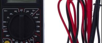
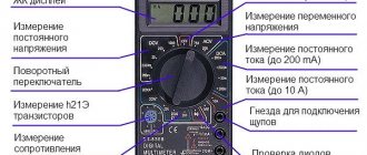
Device structure:
- electronic screen;
- name of designation;
- value switch;
- power button or special control position;
- probe sockets;
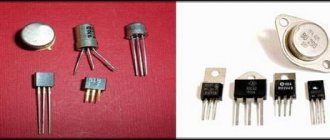
- special connectors for testing transistors (not available on all models);
- buzzer or dial indicator LED;
- power supply.
The main element is the designation scale (name). Inaccurate setting of parameters can lead to burning of the radio component, fuse or the device itself.
The operating principle is based on the use of a dual integration analog-to-digital converter. This is implemented using a controller. The converter compares the received signal with the reference signal and displays the value on the screen.
Analog
Without going into too much scientific definition, an analog device differs from a digital device by the presence of dial gauges. Pointer models are valued by amateurs and professionals for the smooth movement of the pointer. The downside is that the measurements are not very accurate.
Digital
A digital instrument differs from an analog instrument in clear and accurate readings, which are displayed in numbers on the dial. This is why he is valued.
Varieties
There are two options for the multimeter:
- analog;
- digital.
Analog
In analogue, the reading is looked at by the movement of the arrow relative to the scale, where there are special symbols (voltage, current, resistance). If you use a Chinese model, you may experience inconvenience due to the way the scale is applied. Although there is a significant error in the results, this design of the device is still popular due to its affordable cost. If you require accurate measurement readings, you must use a trim resistor.
Digital
All data is displayed on the screen, which can be LED or LCD. The ease of use and accuracy of readings attracts consumers.
Digital version
New graphical multimeters can be compared to simple oscilloscopes because they display the waveform. And some developments may be compatible with a computer, and then the device can be controlled through it. That is, the multimeter incorporates more and more functions, allowing you to simplify your work and replace several devices at once.
Features of Chinese multimeters
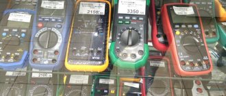
When visiting Chinese online trading sites, your eyes widen at the variety of devices. It seems that the characteristics are the same, but the names and prices are different. I hope it won’t be a revelation to anyone that almost all multimeters are manufactured at one factory, and brands are ordered by trading organizations.
However, the accuracy of the devices is decent - the error is less than 1%. This is normal even for European models.
Most multimeters are powered by AAA batteries rather than Krona batteries, which have a shorter cell life. Even inexpensive models are equipped with display backlighting, which is important for installers.
Well, as a rule, the price for them is not high, so if they are used harshly, it is not a shame to replace them. But, regardless of the price, installers’ devices last for several years in harsh conditions, even with a broken case.
Application
There are times when a person, being a professional in some field not related to electricity, has absolutely no idea why a multimeter is needed. This is possible because until recently, literally a couple of decades ago, these devices were produced only in analog versions and were quite expensive.
They were used mainly by professional electricians, they were cumbersome, and sometimes required the use of an additional power source.
Recently, multimeters have been made compact, inexpensive, and have become much easier to use. Any thrifty owner now has at least the simplest model from a large family of these devices.
After all, if the cause of a malfunction of any household appliance is established, then eliminating it may be within the power of an ordinary person who does not have the professional knowledge and skills of an electrician. Moreover, often, having such a useful measuring device at hand, its owner does not always use all the functions of the multimeter.
The multimeter is used when repairing electrical appliances, debugging circuits, and electronic devices. In everyday life, it can be used in repairing electrical household appliances, electrical parts of cars, motorcycles, troubleshooting electrical networks, installing wiring, and repairing radio equipment. The scope of application is very wide.
Symbols on the multimeter
A multimeter is an electrician's dream. There is no need to use multiple devices to switch from one operation to another.
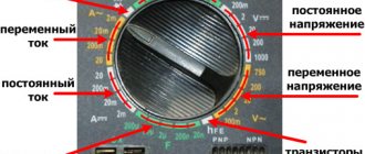
The instrument scale is an important element. Incorrect operation leads to measurement errors or malfunction of the device. To do this, you need to know all the symbols on it.
The scale consists of circular sectors with icons indicating parameters. Each sector is responsible for a specific parameter. They are all divided by lines.
The kit includes probes. Golden rule: plus is red, black is responsible for the rest. Probe connection sockets:
- "COM" socket. This is a minus, mass. The black probe connects here. This is important when measuring polar parts.
- Hole “VΩCX+”. This is the positive socket to which the red wire is connected. It is used in all measurements except current.
- "10A" socket. Used to measure current up to 10 A. The value can be any - 20 A, 30 A. This is a very high current. It is important not to burn the device. If an inscription appears near the “UNFUSED” socket, then the measurement is carried out without a fuse. The multimeter can only be connected in series during the operation.
- "MACX". A probe is connected here to measure low currents - up to 0.2 A.
The red triangle with the warning label "MAX 750" indicates the voltage measurement limit. The number may vary.
If the measurement limits are not known, set the maximum on the scale. Do not touch the metal part of the probe under any circumstances - if in some cases this will lead to a measurement error, then in severe cases it will lead to electric shock.
Decoding the multimeter scale symbols by sector:
- "DCV" - constant voltage;
- "ACV" - alternating voltage measurement;
- "DCA" - constant current scale;
- "ACA" is the AC icon.
Designations on the resistance scale in the standard version: 20 Ohm, 200 Ohm, 2 kOhm, 20 kOhm, 200 kOhm, 2 MΩ, 20 MΩ, 200 MΩ. They may be different. To measure, the pen is placed in the “Ω” sector.
On some models, constant voltage is indicated by a dash with the letter V: “V—”. Alternating voltage - the letter V with a wave.
Alternating current
The symbol for alternating current is similar to alternating voltage - a wavy line followed by the letter A. To measure alternating current, rectifier diodes are introduced into the circuit. The tseshka is poorly suited for measuring this parameter. For this you need a current clamp.
D.C
The designation for direct current is similar to direct voltage - a solid or broken line near the letter A: “A—”. Direct current is designated "DCA" or simply "DC". The regulator is exhibited in this sector. To measure the parameter, we connect the circuit - the device in parallel. The parameter is measured in one conductor, so we include a multimeter in it, which, in addition to passing current, takes measurements.
We use dialing
If you look closely at the front panel of the tester, you can see several additional functions that we have not yet talked about. Some of them are used only by experienced radio technicians, so there is no point in telling a home electrician about them (they are unlikely to be useful in everyday use anyway). But there is another important tester mode that you may use - dialing (we have indicated its designation in the picture below). For example, to find a break in the neutral wire in a circuit, you need to ring the electrical wiring, and if the circuit is closed, you will hear a sound indication. To do this, you just need to connect the probes to the required 2 points of the circuit.
Again, a very important nuance - the power on the section of the circuit that you are going to call must be turned off. For example, if you decide to test the wiring in your house, turn off the input circuit breaker in the distribution panel while you work. It is highly not recommended to use a multimeter with the power connected!
How to connect wires to a multimeter
Let's look at connecting electrical wires to the meter. Such wires are called probes. A probe is an electrical wire with a metal tip at the end and a plastic current-protective sheath.
Main connectors for probes:
- The black wire is considered zero, negative, grounding. Connects to the connector marked “COM”.
- To measure current less than 200 mA, there is a connector marked “VΩmA”. It is better not to try to measure a current strength of a higher value - either the fuse or the multimeter itself will not withstand it.
- Connectors for measuring high currents are designated “10 ADC”. This means that the tester is capable of measuring current from 200 mA to 10 A. The number may be different - it shows the measurement limit.
Video on the topic
Detailed instructions on how to work with a dial-type multimeter are given below in the video:
To understand all the features of the popular DT9205A tester model, watch the video below:
For more information on how to check a thermocouple using a multimeter, see the video:
A multimeter is an electrical device with combined functionality. It is used to determine network voltage, current, electrical resistance, and this list is only a minimum set of functions.
How to set up a multimeter
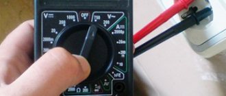
Let's look at how to properly use a digital multimeter for dummies. After turning on the device, move the knob selector to the desired measurement sector - voltage, current, ohmmeter, temperature, ringing or others. Knowing the approximate parameters of the measured quantities, we set a larger value in the sector. If the value is incorrectly selected, when measuring the voltage, 1 will appear in the most significant digit. This will indicate infinite voltage. The pointer tester will simply go off scale and point the needle point blank. If we don’t know the value of the parameter being measured in advance, then we set the highest value and touch it with the probes. If the value on the screen is lower than the next segment limit, then turn the knob to a lower value. In analog, this process is repeated if the needle reacts somehow, almost without deviating from zero.
Detailed instructions for using the tseshka come with each copy. It is important to learn how to work with the device that you have, because the differences are sometimes significant.
We measure the current strength
In order to independently measure the current strength in a circuit with a multimeter, you must first decide whether direct or alternating current flows through the wires. After this, you need to find out the approximate value in Amperes in order to select the appropriate socket for connecting the black probe - “VΩmA” or “10 A”. We recommend that you initially insert the probe into the connector with a higher current value and if a lower value is displayed on the display, switch the plug to another socket. If again you see that the measured value is less than the setting, you need to use a range with a lower value in Amperes.
Please note that if you decide to use a multimeter as an ammeter, you need to connect the tester to the circuit in series, as shown in the picture:
How to use a multimeter
For those who purchased a tester, the answer to the question of how to use a multimeter is relevant. The superdevice measures many parameters, replacing a dozen conventional testers.
Setting up a certain device is simple - you just need to use the scale switches and probes correctly.
Resistance measurements
The resistance measurement function allows you to measure the resistance of a resistor, understand its health and analyze its characteristics. There are several measurement indicators - from 200 Ohms to 2 Megohms and more. If you mix up the measurement scale, nothing will happen to the device; the needle will simply either sway a little and not allow you to accurately track the value, or it will go off scale.
The response limit between the probes is 70 Ohms. If it is less, a beep sounds. This function is convenient for checking the circuit for a short circuit.
Voltage measurements
The tester allows you to measure different types of voltage. Algorithm to work as a tester, a multimeter for beginners to measure the voltage from a battery:
- For the test, we will set the measurement limit on the scale. There are several values for DC voltage. To determine your choice, inspect the battery - the operating voltage of the element is written on the marking.
- We set the maximum value to be slightly higher than that displayed on the power source - this way the measurement will be more accurate.
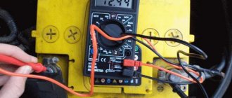
- We connect the tester to the power source or in parallel to the voltage measurement area. We stick the black probe into the “minus” hole of the multimeter - “COM” and to the “minus” of the power source. The red one goes into the hole marked “VΩmA”, the other end goes into the “plus” of the battery.
- Numbers indicating the power supply voltage will appear on the LCD screen. Let's look at the meaning.
If the tested voltage value is unknown, turn the switch up and decrease the maximum as testing progresses.
Alternating voltage is removed in a similar way. The voltage type switch must select its type, rearrange the measurement limit. Then we insert the probes into the holes in the sockets of the tank, and after that into the network. Here you cannot confuse “plus” and “minus”, so the order of connection is not important.
Measuring current with an ammeter
We remove the red probe from the standard position into the current measurement socket - “10A”, “20A” or “MACX”, depending on the expected current strength. It's always better to start with larger values and work your way down to smaller ones.
Diode check
On the measurement scale we find an image of a diode. This test is for diodes and circuits less than 50 ohms. The diode only rings in one direction. A faulty diode will ring in both directions. Serviceable - in one direction it will show 1 and the buzzer will sound, in the other it will show a specific value.
Checking capacitor capacity
You can check the capacity of this electronic part in different ways:
- In testing mode. It is more convenient to observe the arrow model. If there is a breakdown, the needle deviates and immediately returns back.
- Check without soldering. To do this, we select a similar capacitor with the same parameters and solder it into the circuit parallel to the one being tested. If the device works, then the first part was faulty. This method is not applicable to high voltage circuits.
- The main one is desoldering from the circuit. Polar capacitors are checked by correctly connecting the “pluses” and “minuses” of the multimeter and the capacitor. If this rule is ignored, the electrolyte boils with breakdown of the dielectric and an explosion occurs. The dielectric is paper, and the top of the part is artificially weakened, so only the top breaks, and does not explode the circuit completely.
- When measuring non-polar devices, the polarity of the power supply does not need to be observed.
Polar capacitors with a capacity of more than 0.25 µF are checked as follows:
- The element is discharged by short-circuiting the legs with a metal object.
- Switch to ohmmeter mode.
- Touch the probes to the legs, taking into account the polarity.
The capacitor charges for a few seconds. When the buzzer beeps at the zero mark, the condenser has a short circuit. At 1 - internal break. Such electrical parts are thrown away. If the unit does not come out immediately, the condenser is working properly.
There is less fuss with non-polar ones. We set the ohmmeter to megaohms. The device readings should exceed 2 Mohms.
Temperature measurement
Although the device has an appropriate connector and sensor, for measurement you will need to connect a temperature probe. The common range of measured temperatures is 20 - 1000 degrees. Special temperature probes have a wider measurement range.
Ringing mode
This is one of the most requested features. It was possible to check the integrity of the circuit before - with an ohmmeter. Now, in addition to indicating the continuity of the circuit, a buzzer sound is heard on the screen. It is from this that the phenomenon received the nickname “chain continuity.” Sound increases the speed of solving - no need to be distracted by the screen. We put the handle in the ringing position and check the chain with probes. There is sound - that means everything is in order and we move on to the next section of the circuit. The ringing mode is a useful property for mass measurements in bundles of wires when searching for one faulty one.
Measuring resistance
Well, the safest thing in relation to the safety of the multimeter is to use a device to measure the resistance of circuit elements. In this case, you can set the switch to any range of the “Ω” sector, and then select the appropriate setting for more accurate measurements. A very important point - before using the device to measure resistance, be sure to turn off the power in the circuit, even if it is a regular battery. Otherwise, your tester in ohmmeter mode may show an incorrect value.
Most often, you have to measure resistance with a multimeter when repairing household appliances yourself. For example, if the iron does not work, you can measure the resistance of the heating element, which is most likely faulty.
By the way, if, when measuring the resistance on a section of the circuit with a multimeter, you saw the value “1”, “OL” or “OVER” on the display, then you need to move the switch to a higher range, because at the setting you select, an overload occurs. At the same time, if “0” is displayed on the dial, move the tester to a smaller measurement range. Remember this point and using a multimeter when measuring resistance will not be difficult!
Checking the electrical wiring
When installing new or repairing old wiring, there is always a need to test the cables, as well as check the functionality of electrical installation products and circuit breakers. All these operations can also be successfully carried out using a multimeter.
Correct use of a multimeter, this universal measuring instrument with many functions and capabilities, helps to significantly improve the operating conditions of equipment.
A multimeter helps to timely identify the need for its repair, while increasing the maximum service life. This ultimately allows owners to avoid unnecessary costs for repairs and renovations.
