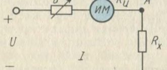
Dependence of ammeter and voltmeter readings on the conductor used in the circuit
First, let's conduct an interesting experiment. Let's assemble an electrical circuit from a current source, a switch, an ammeter and a voltmeter. We will also include conductors made of various materials in this circuit. They are fixed on a special panel. We will connect a voltmeter in parallel to these same conductors (Figure 1).
Our conductors are designated as follows: AB - iron wire, CD - nickel wire, EF - copper wire.
These conductors have the same length and cross-section.
Figure 1. Dependence of current on the conductor used in the circuit
First we connect the iron wire AB . Let us record the readings of the ammeter and voltmeter after closing the key.
Now let's switch to nickel wire CD . We will notice that the current in the circuit has decreased.
Let's try the third conductor: EF . Now the current has increased significantly .
Have you forgotten that in our experiment there was also a voltmeter? We connected it to each of the conductors in turn.
Each time we got the same voltage value. It didn't change.
Use of substances for the manufacture of conductors and isolates
Which substances have the highest resistivity values? Of course, with dielectrics. For example, ebonite and porcelain practically do not conduct electricity. That's why they are used as insulators .
Pure metals have the lowest resistivity. Silver and copper are the best conductors of electricity.
What substances are conductors used in practice made from? Most often, copper, aluminum and iron wires are used for wiring electrical circuits.
In Table 1, you may also have noticed the resistivity values for alloys of several substances. They have quite large values. For what? They are usually used for the manufacture of devices that need to have a high resistance for normal functioning, but still pass current.
Dependence of current on the properties of conductors
You already know that current depends on voltage. After all, voltage is a characteristic of the electric field.
But in our experience the tension remained constant. This means that the current strength has another dependence.
The current strength in the circuit depends on the properties of the conductors included in the electrical circuit.
Resistivity values of some substances
Table 1 shows the resistivity values of some substances.
| Substance | $\rho$, $\frac{Ohm \cdot mm^2}{m}$ | Substance | $\rho$, $\frac{Ohm \cdot mm^2}{m}$ |
| Silver | $0.016$ | Manganin (alloy) | $0.43$ |
| Copper | $0.017$ | Constantan (alloy) | $0.50$ |
| Gold | $0.024$ | Mercury | $0.96$ |
| Aluminum | $0.028$ | Nichrome (alloy) | $1.1$ |
| Tungsten | $0.055$ | Fechral (alloy) | $1.3$ |
| Iron | $0.10$ | Graphite | $13$ |
| Lead | $0.21$ | Porcelain | $10^{19}$ |
| Nickelin (alloy) | $0.40$ | Ebonite | $10^{20}$ |
Table 1. Resistivity of some substances (at $t = 20 \space \degree C$)
Please note that these values are valid at a temperature of $20 \space \degree C$.
The resistivity of a substance depends on temperature.
Experiments have shown that at a certain temperature for each substance, a dielectric can become a conductor (semiconductor). It has also been experimentally proven that with increasing temperature the resistivity of metals increases.
Causes of Electrical Resistance
What is the reason for the resistance?
Remember the lesson “Electric current in metals“. Electrons, moving under the influence of an electric field, acquire some direction. But at the same time, the chaotic nature of their movement remains. We also compared this movement to a flock of midges that is carried away by the wind.
So, electrons are brought into ordered motion by an electric field. At the same time, they interact with ions of the crystal lattice. What happens? Orderly movement slows down . Now fewer electrons pass through the cross section of the conductor in $1 \space s$. This means the current decreases.
Let us draw a conclusion from our reasoning.
The reason for resistance is the interaction of moving electrons with ions in the crystal lattice.
It is logical that different conductors will have different resistance values. The whole point will be in the differences in the structure of their crystal lattice. In addition, the length of the conductor and its cross-sectional area will be important. We will talk about this in the following lessons.
Experimental results
What conclusions can we draw after all the calculations?
- Of two nickel wires of the same thickness, longer wire has greater resistance.
- The nickel wire with a smaller cross-section a greater resistance . In this case, the length of the wires was the same
- Nickelin and nichrome wires have different resistances with the same dimensions
Exercises
Exercise No. 1
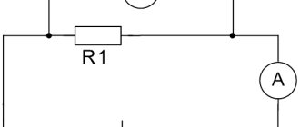
Draw a diagram of the circuit shown in Figure 1 and explain the experiment carried out on this drawing.
The electrical circuit diagram is shown in Figure 2. The conductor is indicated by a rectangle.
Figure 2. Electrical circuit diagram for the experiment.
During this experiment, various conductors are used. At the same time, the values of the devices are recorded. The current strength varies depending on which conductor is connected to the circuit. The voltage at the ends of different conductors remains constant all the time.
This experiment proves the connection between current strength and a property of a conductor called electrical resistance.
Exercise No. 2
Express the following resistances in ohms: $100 \space mOhm$;
$0.7 \space kOhm$; $20 \space MOhm$. Given: $I_1 = 100 \space megohm$ $I_2 = 0.7 \space kOhm$ $I_3 = 20 \space megohm$
Show solution and answer
Hide
Solution:
$I_1 = 100 \space mOhm = 100 \cdot 0.001 \space Ohm = 0.1 \space Ohm$, $I_2 = 0.7 \space kOhm = 0.7 \cdot 1000 \space Ohm = 700 \space Ohm$, $I_3 = 20 \space MΩ = 20 \cdot 1 \space 000 \space 000 \space Ohm = 20 \space 000 \space 000 \space Ohm$.
Answer: $I_1 = 0.1 \space Ohm$, $I_2 = 700 \space Ohm$, $I_3 = 20 \space 000 \space 000 \space Ohm$.
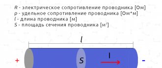
Unit of resistivity
To determine the unit of measurement of resistivity, we turn to the formula $\rho = \frac{RS}{l}$.
The unit of resistance is $1 \space Ohm$, the cross-sectional area is $1 \space m^2$, the length is $1 \space m$.
Let's put all this into the formula:
$[\rho] = \frac{1 \space Ohm \cdot 1 \space m^2}{1 \space m} = 1 \space Ohm \cdot m$.
The cross-sectional area of the conductor is usually small, so it is convenient to express it in $mm^2$. Therefore, the resistivity of a conductor is often measured in $\frac{1 \space Ohm \cdot 1 \space mm^2}{1 \space m}$.
Ideal current source
The ideal current source is an active element whose current does not depend on the voltage at its terminals. It is assumed that the internal resistance of an ideal current source is infinitely large, and therefore the parameters of the external electrical circuit, on which the voltage at the source terminals depends, do not affect the source current. The symbols of an ideal current source are shown in Fig. 1
The arrow in the current source or the signs “+” and “—” indicate the positive direction of the current i(t)
or the polarity of the source, i.e. the direction of movement of positive charges.
Nowadays it is customary to denote current sources with the letter J, and the lower conventional graphic image is most often used.
Ideal current source
As the resistance of an external electrical circuit connected to an ideal
At a current source, the voltage at its terminals and, accordingly, the power developed by it increase indefinitely. Therefore, an ideal current source, as well as an ideal voltage source, is considered as a source of infinite power.
A current source of finite power is depicted as an ideal current source with a passive element connected in parallel to its terminals, which characterizes the internal parameters of the source and
Representing a theoretical concept, a current source is used in a number of cases to calculate electrical circuits.
Some semblance of a current source can be a device consisting of a battery connected in series with an additional high resistance. Another example of a current source can be a five-electrode amplifying electron tube (pentode). Having an internal resistance incommensurably greater than the resistance of the external electrical circuit, these devices deliver a current that is almost independent of changes in the external load over a wide range, and it is in this respect that they are similar to a current source.
Why does the conductor “resist”?
The voltage U applied to the ends of the conductor creates an electric field inside it, which sets in motion the free electrons of the substance. Electrons, having received additional kinetic energy, begin to move in an orderly manner in one direction, thereby creating an electric current in the circuit.
As they move, electrons collide with neutral and charged atoms that make up the conductor and lose energy. The mass of an atom exceeds the mass of an electron by thousands of times, so their collision leads to a change in the direction of electron motion and a loss of speed (“braking”).
This creates resistance to the flow (increase) of current.
Rice. 1. Electric current in a conductor is limited by the collision of electrons with atoms.
Measuring internal resistance.
There are several methods for measuring internal resistance. Two of them are specified in GOST R IEC 61960-2007. Before measuring using any of the methods below, the battery must be fully charged. Tests are carried out at a temperature of 20±5ºC.
Measuring internal resistance using the AC method (a.c.)
This method measures impedance, which at 1000 Hz is approximately equal to resistance.
Electrical impedance (complex electrical resistance) (English impedance from Latin impedio “to hinder”) is the complex resistance between two nodes of a circuit or two-terminal network for a harmonic signal.
Description of the methodology from GOST
For one to five seconds, we measure the root-mean-square value of the alternating voltage Urms, which occurs when an alternating current with a root-mean-square value Irms passes through the battery, following with a frequency of 1000 Hz. Internal resistance Ra.c., Ohm is calculated using the formula Ra.c.= Urms / Irms.
Irms (rms – Root Mean Square – root mean square value).
The alternating current must be of such a value that the peak voltage does not exceed 20 mV.
This method is difficult to implement at home without special equipment. The popular YR1035 device does an excellent job of measuring with an accuracy of 0.01 mOhm. Chargers SKYRC MC3000, Opus BT-C3100V2.2, Liitokala Lii-500 are also measured using the AC method, but with very mediocre accuracy.
Measuring internal resistance using the direct current (dc) method
This method can be performed at home using a regular voltmeter and ammeter and a pair of suitable load resistors. As resistances, it is quite possible to use several car incandescent lamps or an improvised resistor made of nichrome wire.
Description of the method from GOST
- We discharge the battery with direct current I1= 0.2 In. At the tenth second we measure the voltage value U1 at the battery terminals.
- We increase the discharge current to the value I2=In. In the next second, we measure the value of voltage U2 at the battery terminals.
Internal resistance Rd.c., Ohm is calculated using the formula Rd.c. = (U1-U2)/(I2-I1)
- Iн – rated battery discharge current.
Circuit for measuring internal resistance using the direct current (dc) technique
The resistances R1 and R2 are selected in such a way that currents I1 and I2 of the required magnitude flow. You need to focus on the rated discharge current of the battery.
The voltmeter must be connected directly to the source poles to eliminate the influence of voltage drop on the wires.
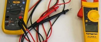
How to use a multimeter correctly: instructions for dummies
Let's look at how to measure several electrical characteristics.
Potential
Algorithm for determining voltage:
- Set the mode to ACV or DCV position in the expected interval.
- Connect the black wire to the COM connector, the red wire to the VΩmA connector.
- Connect the tips of the probes to the circuit contacts. For example, insert batteries into the holes of a socket or onto the poles.
- Take a measurement.
The number displayed on the display is the voltage value in volts. The minus sign indicates that the polarity has been reversed. If the multimeter supports the hold function, the value can be locked using the HOLD button. This is convenient for a large chain of measurements.
Current strength
This characteristic is measured only when the tester is connected in series to the circuit and the power is turned on. Most devices make it possible to determine current strength up to 10 A, since large values are rarely used in everyday life. To carry out measurements, a break is made in the circuit. Further actions according to the following scheme:
- The black probe goes into the COM socket.
- Red - into the connector up to 200 mA or 10A.
- Use the tips to gently touch the contacts.
- Read the voltage value from the display.
When working with exposed wires, you must follow safety precautions to prevent electric shock.
Resistance
This characteristic can be measured without power supply. The element being tested is simply closed between two probes. If there is no conductivity, a unit is displayed on the screen. Sequencing:
- Set Ω mode by selecting maximum range.
- Insert the probes into the appropriate connectors.
- Check the condition - short the probes to each other. A 0 or small number should appear, which must be taken into account when measuring the resistance of the circuit.
- Throw the ends of the conductors onto the contacts of the object under study.
- The resistance of the element or section of the circuit will appear on the screen.
For accurate measurements, 2-3 attempts are recommended.
Comprehensive analysis
For a resistor and capacitor circuit in series connection, the AC source is specified as:
RC sequence
vin (t) = Vejωt (V is the amplitude of the alternating voltage, j is the imaginary unit (j2 = -1), and ω is the angular frequency of the alternating current source).
It is important to note two points:
- We use the lowercase alphabet for voltage sources to help us understand how they alternate.
- The imaginary unit is shown as "j".
The total resistance of the circuit when the active and reactive elements are connected in parallel.
In order to calculate the total resistance of a circuit composed of active and inductive resistances connected to each other in parallel (Fig. 5, a), you must first calculate the conductivity of each of the parallel branches, then determine the total conductivity of the entire circuit between points A and B and then calculate the total resistance of the circuit between these points.
Figure 5. Circuit impedance when connecting active and reactive elements in parallel. a) – parallel connection of R and L; b) – parallel connection of R and C.
The conductivity of the active branch, as is known, is equal to 1/R, similarly, the conductivity of the inductive branch is equal to 1/ωL, and the total conductance is equal to 1/Z
Total conductivity is equal to the square root of the sum of the squares of active and reactive conductivity, i.e.
(7)
Reducing the radical expression to a common denominator, we get:
(8)
where:
(9)
Formula (9) is used to calculate the total resistance of the circuit shown in Fig. 5a.
Finding the total resistance for this case can also be done geometrically. To do this, you need to construct a resistance triangle on the appropriate scale, and then divide the product of the lengths of the legs by the length of the hypotenuse. The result obtained will correspond to the total resistance.
Similar to the case discussed above, the total resistance when connecting R and C in parallel will be equal to:
(10)
The total resistance can also be found in this case by constructing a resistance triangle.
In radio engineering, the most common case is the parallel connection of inductance and capacitance, for example, an oscillatory circuit for tuning receivers and transmitters. Since the inductor always has, in addition to inductive resistance, also active resistance, the equivalent (equivalent) circuit of the oscillatory circuit will contain active resistance in the inductive branch (Fig. 7).
Figure 6. Equivalent circuit of an oscillating circuit.
It will be interesting➡ Inductive reactance
The impedance formula for this case will be:
(11)
Since usually the active resistance of the coil (R) is very small compared to its inductive resistance (ωL), we have the right to rewrite formula (11) in the following form:
(12)
In an oscillating circuit, the values of L and C are usually selected so that the inductive reactance is equal to the capacitive reactance, i.e., so that the condition is met
(13)
If this condition is met, the total resistance of the oscillatory circuit will be equal to:
(14)
where L is the inductance of the coil in H;
C is the capacitance of the capacitor in F;
R is the active resistance of the coil in Ohms.
Ohm's law formula
Ohm's main discovery was that the amount of electric current flowing through a metal conductor in a circuit, at any given temperature, is directly proportional to the voltage applied to it. Ohm expressed his discovery in the form of a simple equation describing the relationship between voltage, current and resistance:
\[E=IR\]
In this algebraic expression, voltage (E) equals current (I) times resistance (R). Using algebra, we can transform this equation into two other variants, solving it for I and R respectively:
\
\