Types of voltmeters
If we talk about the types of voltmeters, they are divided into:
- Voltage meters (DC) marked B2. Widely used as a wiring test device for automobiles and other equipment;
- Voltage meters (alternating) are marked as B3. As a converter of variable parameters into constant indicators with amplification of the output signal;
- Pulse sensitivity devices are designated B4 and are used when taking characteristics obtained as a result of short voltage pulses. With their help, interference is detected, that is, poorly made contacts. They are mainly used when it is necessary to test electrical automotive wiring, as well as conventional microcircuits, along with others;
- B5 with phase distribution with two sensitivity zones, when you can take two indicators at once. With their help, measurements are carried out where the first harmonic component is present. In everyday life, such equipment is practically not used;
- Selective frequency search (B6) with significant dimensions, reminiscent in design of radio signal receivers;
General value or universal, allowing you to take readings in any type of circuit (B7). Shunts are included in the package to make the connection as secure as possible.
2.4.1 Pulse code digital voltmeters
Pulse code (with bit-by-bit balancing) digital voltmeters implement the principle of a compensation method for measuring voltage. The block diagram of such a voltmeter is shown in Fig. 2.13.
The measured voltage U'x received from the input device is compared with the compensating voltage UK generated by the precision divider and the reference voltage source. The compensation voltage has several levels, quantized in accordance with the binary-decimal number system. For example, a two-digit digital voltmeter designed to measure voltages up to 100 V may include the following voltage levels: 80, 40, 20, 10, 8,4,2, 1 V.
Figure 2.13 Block diagram of a pulse-code voltmeter
A comparison of the measured U'x and compensating voltage UK is carried out sequentially according to the commands of the control device. The comparison process is shown in Fig. 2.14.
Control pulses Uу at certain time intervals switch the resistances of the precision divider in such a way that voltages sequentially appear at its output: 80, 40, 20, 10, 8, 4, 2, 1V; At the same time, a comparison device is connected to the corresponding output of the precision divider. If UK > U'x, then a signal Uср is sent from the comparison device to turn off the divider of the corresponding link, so as to remove the UK signal. If UK < U'X, then no signal is received from the comparison device.
After the comparison process is completed, the signal UK0D of the position of the precision divider keys is the code that is read by the digital reading device.
In Fig. For clarity, Fig. 2.14 shows the process of encoding an analog voltage with an amplitude of 63V, from which it can be seen that the code corresponding to this signal will be 01100011.
The process of measuring voltage in a pulse-code device is reminiscent of weighing on a scale, which is why the devices are sometimes called bit-balancing devices. The accuracy of a pulse code device depends on the stability of the reference voltage, the manufacturing accuracy of the divider, and the response threshold of the comparing device.
To create normal noise immunity (60-70 dB), a noise suppression filter is installed at the input of the devices; Therefore, such a device has good technical characteristics and is used as a laboratory one.
The first digital instruments were created using the weighing method, but now time-pulse type devices are more common.
Figure 2.14 Graphs explaining the operation of a pulse code voltmeter
Appearance of the voltmeter
There are three types, thanks to which you can distinguish the parameters of voltmeters:
- Providing portability, characterized by autonomous operation with small size and weight, as well as an easy-to-carry body part. To take characteristics, they are usually equipped with either “crocodile clips” or clothespins - these are two metal contacts;
- The stationary plan weighs significantly more due to the presence of increased sensitivity. Their installation is carried out in places of complex equipment; here they are necessary to be able to constantly monitor the general condition of both refrigeration and heating units, along with the air conditioning system. In cases where the power comes from a generator, their presence is simply necessary so that in the event of a failure in a specific section of the circuit, the fault can be immediately detected and eliminated;
- For installation in shields, devices are used that are average in weight and size between stationary and portable models. This option is considered justified and appropriate
Time-pulse voltmeter with a linearly varying voltage generator.
The block diagram of a time-pulse digital voltmeter and timing diagrams explaining its operation are presented in Fig. 2.15, This type of voltmeter includes an ADC with intermediate conversion of the measured voltage into a proportional time interval. The ADC includes: linearly varying voltage generator GLIN; two comparison devices I and II; trigger T; AND logic circuit; counting pulse generator; pulse counter and digital readout device.
The discrete signal of measuring information at the output of the converter has the form of a packet of counting pulses, the number of which is Nproportional to the value of the input voltage U'x (i.e. Ux). The voltage UGLIN linearly varying with time from GLIN is supplied to the inputs I of both comparison devices. The other input of the comparison device I is connected to the housing.
At the moment of time when the voltage UGLIN = 0 at the input of the comparison device I, a pulse UUSI appears at its output, conditionally fixing the zero level of the input signal. The website https://intellect.icu talks about this. This pulse, applied to the single input of the T trigger, causes a positive voltage to appear at its output. The trigger is returned to its original state by a pulse UусII coming from the output of comparison device II. The UycII pulse occurs at the moment of equality of the measured U'x and the linearly varying voltage UGLIN. A pulse UT generated at the output of the trigger with a duration of Δt = U'XS (here S is the conversion coefficient) is fed to the input of the AND circuit, the second input of which receives the signal UGSI from the generator of counting pulses, following with a frequency ƒ0 = 1/T0.
Figure 2.15 Digital voltmeter with pulse-time conversion: a - block diagram; b - timing diagrams.
At the output of the AND circuit, the Ucount signal appears only in the presence of UT and UGSI pulses at both of its inputs, i.e. counting pulses pass through the AND circuit when there is a signal at the trigger output. The number of counting pulses N ≈ ∆t/T0 passing through the circuit And is counted by the counter and displayed on the indicator of the digital reading device (DOC) of the device.
From the last two formulas we find the measured voltage:
U'x = N/(f0S), (2.14)
In this voltmeter, the value f0S is selected equal to 10m, where m = 1.2, 3,..., (the number m determines the position of the decimal point in the digital readout) so the device directly displays the value of the measured voltage.
The considered cycle of operation of a digital voltmeter is periodically repeated. In this case, the CLIN is returned to its original state and the circuit is prepared for the next measurement automatically. Digital AC voltmeters are built using the same principle. In these voltmeters, the alternating current voltage is pre-rectified and then supplied to the comparison device II.
Relation (2.14) does not take into account discreteness errors due to the discrepancy between the moment of appearance of counting pulses and the beginning and end of the interval At. However, an even greater error is introduced by the nonlinearity factor of the conversion coefficient S. A disadvantage of the pulse-time conversion method is also its low noise immunity. Noise interference superimposed on the measured voltage Ux changes it and, therefore, changes the moment of appearance of the pulse UсII, which determines the duration Δt of the counting time. Therefore, voltmeters built according to this scheme are the least accurate among digital ones.
The duration of Tx is directly proportional to the measured voltage and inversely proportional to the tangent of the voltage slope GLIN
Description of the operating principle of a voltmeter
In terms of their functionality, voltmeters can be either mechanical or electronic, depending on the method of making measurements:
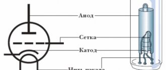
- Electromechanical models have a pointer mounted on a frame, which is mounted on an axis (permanent magnet). The applied voltage, which creates an electric and magnetic field, deflects the pointer with the frame, pointing to the scale mark.
- The sensitivity of the devices is different, expressed by the coefficient between the reading on the scale and the actual voltage. Pointer vibrations are eliminated using an aluminum induction damper.
- Counterweights prevent gravity from affecting the needle readings. All parts are steel and will not wear off, and the rods are polished to reduce friction;
Electronic models are either analog or with electronic “filling”.
- The former are very similar in appearance to conventional mechanical ones; they are also available with a built-in arrow.
- The built-in converter system does not allow the needle to oscillate randomly, ensuring measurement accuracy.
- The latter are equipped with an internal controller and a display for displaying signals.
- Such devices are characterized not only by greater measurement accuracy, but also by light weight, compact dimensions, along with reliability.
- Obtaining more accurate measurement results directly depends on what class of transducer is installed in a particular case.
The display shows the already translated signal in the form of a digital code from the received voltage parameters.
Operating principle of digital voltmeters
The operating principle of digital measuring instruments is based on discrete and digital representation of continuous measured physical quantities. A simplified block diagram of a digital voltmeter (Fig. 2.12) consists of an input device, an ADC, a digital readout device and a control device.
The input device contains a voltage divider; in AC voltmeters it also includes an AC-DC converter.
Figure 2.12 Simplified block diagram of a digital voltmeter
Block diagram of a digital voltmeter
An analog-to-digital converter converts an analog signal into a digital signal, represented by a digital code. The analog-to-digital conversion process is the essence of any digital device, including a voltmeter. The use of binary decimal code in digital voltmeter ADCs makes it easier to convert the code back to a decimal number, which is reflected by a digital readout device. A digital readout device records the measured value. The control device combines all components of the voltmeter.
Based on the type of ADC, digital voltmeters are divided into two main groups:
• pulse code (with bit-by-bit balancing);
• time-pulse.
The analog-to-digital converter of voltmeters converts the DC signal into a digital code, which is why digital voltmeters are also considered DC instruments. To measure alternating current voltage, a converter to direct voltage, most often an average rectified value, is placed at the input of the voltmeter.
Let's analyze the main technical characteristics of the average digital DC voltmeter:
• measurement range: 100 mV, 1 V, 10 V, 100 V, 1000 V;
• input impedance - high, usually more than 100 MOhm;
• sensitivity threshold (other names - quantum or discreteness unit) in the range of 100 mV can be 1 mV, 100 μV, 10 μV;
• number of characters (length of the digital scale) - the ratio of the maximum measured value in this range to the minimum; for example: a measurement range of 100 mV at a quantization level of 10 μV corresponds to (100-10-6)/(10 • 10-9) = 104 characters;
• noise immunity.
Accuracy of digital voltmeters. The distribution of error over the measurement range is determined by the limit of permissible relative, basic error , which characterizes the SI accuracy class:
(2.13)
where u is the measured voltage; Uк - final value of the range
measurements.
Performance. Modern ADC circuits used in digital voltmeters can provide very high speed, however, for reasons of accurate recording of the result obtained, in digital voltmeters it is reduced to approximately 20-50 measurements per 1 s.
How to use and connect a voltmeter
In order for the obtained data to be as accurate as possible, the device must always be connected in parallel to the area where measurements are planned using terminals or clamps for special purposes.
High voltage voltage is not intended to be measured by weak voltmeters, the parameters of which are in no way designed for this.
- The devices have different measurement ranges, ranging from millivolts to kilovolts.
- The sensitivity of microvoltmeters allows you to measure millionths of a volt.
- The range of the device is taken into account primarily so as not to cause a short circuit.
In addition, devices designed for direct current are absolutely not suitable for measuring alternating current values. The use of universal models is carried out only after selecting the appropriate measurement mode.
2.4.2 Voltmeters with pulse-time conversion
The operating principle of a time-pulse (time) type voltmeter is based on the conversion of the measured voltage using an ADC into a proportional time interval, which is filled with counting pulses following at a known stable repetition rate. As a result of this transformation, the discrete signal of measuring information at the output of the converter has the form of a packet of counting pulses, the number of which is proportional to the level of the measured voltage.
Digital voltmeters with time-pulse conversion Voltmeters of this type use an ADC that performs “voltage - time interval - code” conversions. The principle of operation is to compare the measured signal with a reference linearly increasing voltage.
This type of CV measures the instantaneous voltage value. Pulse-time conversion voltmeters are simple and cheap, and have fairly high accuracy. Their main disadvantage is low noise immunity.
There are several circuit solutions used to create time-pulse voltmeters. Let's consider two such schemes.
Characteristics of voltmeters
All models, without exception, have common criteria by which performance is assessed. This does not depend on the principle of operation, nor on the purpose, nor on the method of its execution.
Measurement accuracy is the first parameter that you need to pay attention to before purchasing or using it.
The greater the resistance inside the voltmeter, the less influence it has on the measurement process, thereby reducing the error. In this case, its effect on the electrical circuit is minimal.
Time-pulse voltmeters with double integration.
The principle of operation of a voltmeter is similar to the principle of operation of a circuit with time-pulse conversion, with the difference that here, during the T measurement cycle, two time intervals T1 and T2 are formed. In the first interval, the measured voltage is integrated, and in the second, a certain reference voltage is integrated. The duration of the measurement cycle T = T1+ T2 is deliberately set to be a multiple of the period of interference acting at the input, which leads to an increase in the noise immunity of voltmeters.
In CV with double integration, the “voltage - time interval” conversion (in contrast to CV with pulse-to-pulse conversion) occurs using an integrator. An integrator is a functional block on an operational amplifier that provides communication between the input uin and output uout voltages in the form
Double integration voltmeters are the most popular type of digital voltmeters and multimeters. Their main advantages are simplicity, high noise immunity with sufficient accuracy.
The block diagram of a digital voltmeter with double integration and timing diagrams explaining its operation are presented in Fig. 2.16.
Figure 2.16 Double integration digital voltmeter:
a - block diagram; b - timing diagrams.
The circuit contains an input device, a two-position switch, an integrator, a reference voltage source, a comparison device, a T trigger, a counting pulse generator, a control device, an AND logic circuit, a pulse counter and a digital readout device.
At the beginning of the measurement cycle at t = t0, the control device of the circuit generates a calibrated pulse UIcontrol with duration T1 = T0K, where Ta is the repetition period of the counting pulses; K is the meter capacity. At the moment the edge of the UIcontrol pulse appears, the switch is moved to position 1, and a voltage U/x, proportional to the measured voltage Ux, is supplied to the integrator from the input device. Then, over the time interval T1 = t1 - t0, the voltage U/x (proportional to the measured Ux) is integrated, as a result of which the increasing voltage at the output t1 of the integrator will be: UИ = ∫Ux′dt. At the moment t = t1 control t0
the UIcontrol signal moves the switch to position 2 and a reference negative voltage UION is supplied to the integrator from the reference voltage source. At the same time, the control signal UIcontrol overturns the trigger.
Integration of voltage UION is faster, since it is installed in the circuit. Integration of the reference voltage continues until the output voltage of the integrator again becomes equal to zero (in this case T2 = t2-t1). Therefore, during the second time
interval, a falling voltage t2 is formed at the integrator output
In this case, the longer the duration of the integration interval t1 T2, the higher the amplitude of the measured voltage U'x.
At time t = t2, the voltage UI at the output of the integrator becomes zero and the comparison device (the second input of which is connected to the housing) outputs a signal to the trigger, returning it to its original state. At its output, a pulse Ut of duration T2 is generated, which is supplied to the input of the I circuit. The UGSI signal from the counting pulse generator is supplied to its other input. At the end of the UT pulse coming from the trigger, the measurement process stops.
The conversion of the measured time interval T2 into an equivalent number of pulses N is carried out in the same way as in the previous method - by filling the T2 interval with periodic pulses of the counting pulse generator and counting their number with a counter. On the counter, and therefore on the digital reading device, the number of pulses NUcount, proportional to the measured voltage, is recorded
Ux:
(2.15)
This expression leads to the following formulas:
(2.16)
From the last equalities we get
(2.17)
From the above relationships it is clear that the error of the measurement result depends only on the level of the reference voltage (and not on several, as in a pulse-code device). However, there is also a discreteness error here. The advantage of the device is its high noise immunity, since it is integrating. Based on double integration circuits, devices with a higher accuracy class are produced than devices with GLIN. Voltmeters of this type have a measurement error of 0.005...0.02%.
Digital voltmeters of the highest accuracy class are created in combination: the circuits combine the methods of bit-by-bit balancing and pulse-time integrating conversion.
Double integration voltmeter measures the average voltage value over time T1
Photos of voltmeters
Digital multimeters.
The inclusion of a microprocessor and additional converters in the circuit of a digital voltmeter allows you to turn it into a universal measuring device - a multimeter. Digital multimeters measure AC and DC voltage, current, resistor values, electrical frequency, etc.
When creating digital automatic instruments for measuring resistance, inductance and capacitance, methods associated with converting the measured parameter into voltage or current, frequency or time interval, as well as methods based on bridge and compensation circuits, are widely used.
Fig.35. Simplified circuit of a digital automatic complex resistance meter with a microprocessor
The most widely used are digital automatic devices with a microprocessor, made according to circuits using balanced bridges. Balancing is carried out by automatic regulation of two bridge bodies (for each of the measured parameters). A simplified block diagram of a digital automatic complex resistance meter with a microprocessor is shown in Fig. 35
Figure 2.17 Digital voltmeter with microprocessor
When used together with an oscilloscope, multimeters are capable of measuring time intervals (period, pulse duration, etc.). The presence of a microprocessor in the electrical circuit of the voltmeter allows for automatic correction of measurement errors, auto-calibration and fault diagnostics.
In Fig. Figure 2.17 shows a digital voltmeter with a microprocessor as an example. The main devices of the voltmeter are: microprocessor, ADC, signal normalization and control units.
The signal normalization block, using appropriate converters, converts the input measured parameters (AC and DC voltage, DC resistance, etc.) to a unified signal, which is fed to the ADC input. The latter usually operates using the double integration method. The control unit provides selection of the operating mode for a given type of measurement, control of the ADC, display, and creates the desired configuration of the measurement system.
The basis of the control unit is a microprocessor, which is connected to other nodes through shift registers. The microprocessor is controlled using a keyboard located on the control panel or through a standard interface (interface unit; joint) of a connected communication channel. The microprocessor's operating program is stored in a read-only memory device, ROM, and is supported by a random access memory device, RAM.
For measurements, built-in highly stable and precision resistive reference voltage dividers, a differential remote control amplifier and a number of external elements (attenuator and mode selection device, reference voltage unit uop) are used. All pulse and digital devices are synchronized by clock generator signals.
Control questions:
1. What principle is implemented in pulse-code digital voltmeters?
2. On what principle are time-pulse voltmeters built?
3. Explain the operation of a microprocessor driven digital voltmeter.
4. Explain the working of double integration digital voltmeter.
Answers for the lazy
1. In pulse-code (with bit-by-bit balancing) digital voltmeters, the principle of the compensation method of measuring voltage is implemented. The measured voltage U'x received from the input device is compared with the compensating voltage UK generated by a precision divider and a reference voltage source. The compensation voltage has several levels, quantized in accordance with the binary-decimal number system.
2 The operating principle of a time-pulse (time-based) type voltmeter is based on the conversion of the measured voltage using an ADC into a proportional time interval, which is filled with counting pulses following at a known stable repetition rate. As a result of this transformation, the discrete signal of measuring information at the output of the converter has the form of a packet of counting pulses, the number of which is proportional to the level of the measured voltage.
3 The most widespread are digital automatic devices with a microprocessor, made according to circuits using balanced bridges. Balancing is carried out by automatic regulation of two bridge bodies (for each of the measured parameters).
4 The principle of operation of a voltmeter is similar to the principle of operation of a circuit with time-pulse conversion, with the difference that here, during the measurement cycle T, two time intervals T1 and T2 are formed. In the first interval, the measured voltage is integrated, and in the second, a certain reference voltage is integrated. The duration of the measurement cycle T = T1+ T2 is deliberately set to be a multiple of the period of interference acting at the input, which leads to an increase in the noise immunity of voltmeters.
Classification
With all their diversity, these measuring instruments can be classified according to several parameters. This will help you choose the one you need if you are planning to purchase it.
So, voltmeters can be classified according to:
- operating principle;
- scope of application;
- designs;
- accuracy class.
According to the principle of operation, voltmeters are electromechanical and electronic. The first include simple devices described in the previous chapter - magnetoelectric, electrodynamic, electromagnetic, thermoelectric, rectifier and electrostatic. The second includes devices with digital and analog signal conversion and output to the panel.
According to the scope of their application, devices are manufactured for measuring direct current, alternating current, universal, pulse, phase-sensitive and selective.
By design, they can be portable, which are devices with “crocodile clips” (they can be put in a bag, or even in a pocket) and stationary, which are used indoors. The latter also include panel panels: they are designed for permanent installation in the dashboard.
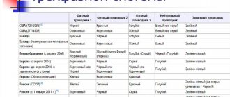
The accuracy class on measuring instruments is marked with a number, and not everyone pays attention to this, but in vain. Sometimes the accuracy of the device is of fundamental importance.
The number not circled shows the relative measurement error, and it is given as a percentage. In Russia there are the following classes of instrument accuracy by relative error: 6, 4, 2.5, 1.5, 1.0, 0.5, 0.2, 0.1, 0.05, 0.02, 0.01 , 0.005, 0.002, 0.001. The indicated figure shows by how many percent the instrument readings may differ from the true value of the measured value. It is important that this is relevant within the operating range of the device, and this range must be indicated on the device. It does not always coincide with the zero mark of the scale: for values close to zero, the probability of error tends to infinity.
If the device has an uneven scale, then the accuracy class is indicated by a number under which the angle sign appears. This means that the error is given in fractions of the scale length.
Read also: Drilling machine quill drawing
The fraction designation shows the error at the end of the scale and at the beginning.
The difference between digital instruments is that the measured range in them is adjustable; this allows for more accurate measurements.
Rules for connecting a voltmeter to an electrical circuit
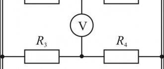
- The voltmeter clamps must be connected to those points in the circuit between which the voltage must be measured. This connection is called parallel (Figure 3).
Figure 3. Parallel connection of a voltmeter to a circuit
You will learn more about the features of parallel connection
- One of the voltmeter terminals has a “ + ” sign. The wire connected to this terminal must be connected to the wire coming from the positive pole of the current source (Figure 4). If you connect the device incorrectly, the voltmeter needle will simply begin to deviate in the other direction.
Figure 4. Maintaining polarity when connecting a voltmeter to a circuit