Electricity is the property of a magnetic field to be transformed into other types of energy. These types of energy can be: mechanical, chemical, steam, laser. The number of consumers and sources of consumption is constantly growing. Therefore, the question of ways to transmit electricity over long distances, preserving power and distributing it, remains open. The article will describe the main and current transmission methods, as well as modern developments in the field of wireless technologies.
General description of the process
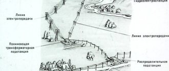
As mentioned earlier, the initial object from which the distribution of electricity begins is today a power station. Nowadays, there are three main types of stations that can supply consumers with electricity. This can be a thermal power plant (TPP), a hydroelectric power station (HPP) and a nuclear power station (NPP). In addition to these main types, there are also solar or wind power plants, however these are used for more localized purposes.
These three types of station are both the source and the first point of distribution of electricity. In order to carry out a process such as the transfer of electrical energy, it is necessary to significantly increase the voltage. The further away the consumer is, the higher the voltage should be. So, the increase can reach up to 1150 kV. An increase in voltage is necessary in order for the current to decrease. In this case, the resistance in the wires also drops. This effect allows current to be transmitted with minimal power loss. In order to increase the voltage to the required value, each station has a step-up transformer. After passing through the section with the transformer, the electric current is transmitted to the central distribution center using power lines. The central distribution station is a central distribution station where direct distribution of electricity is carried out.
Direct current as an alternative
As an alternative to AC power transmission over long distances, constant voltage overhead lines can be considered. Such power lines have the following advantages:
- The length of the overhead line does not affect the power, while its maximum value is significantly higher than that of power lines with alternating voltage. That is, if electricity consumption increases (up to a certain limit), you can do without modernization.
- Static stability can be ignored.
- There is no need to synchronize the frequency of the connected power systems.
- It is possible to organize the transmission of electricity via a two-wire or single-wire line, which significantly simplifies the design.
- Less influence of electromagnetic waves on communications.
- There is virtually no generation of reactive power.
Despite the listed capabilities of DC power lines, such lines are not widespread. This is primarily due to the high cost of the equipment required to convert sinusoidal voltage into direct voltage. DC generators are practically not used, with the exception of solar power plants.
With inversion (a process completely opposite to rectification) everything is also not simple; it is necessary to obtain high-quality sinusoidal characteristics, which significantly increases the cost of the equipment. In addition, one should take into account problems with organizing power take-off and low profitability when the length of overhead lines is less than 1000-1500 km.
Briefly about superconductivity.
The resistance of the wires can be significantly reduced by cooling them to ultra-low temperatures. This would make it possible to bring the efficiency of electricity transmission to a qualitatively new level and increase the length of lines for using electricity at a great distance from the place of its production. Unfortunately, currently available technologies cannot allow the use of superconductivity for these purposes due to economic infeasibility.
General description of the current path
Facilities such as central distribution centers are already located in close proximity to cities, villages, etc. Not only distribution occurs here, but also voltage reduction to 220 or 110 kV. After this, the electricity is transmitted to substations located within the city.
When passing through such small substations, the voltage drops again, but to 6-10 kV. After this, electricity is transmitted and distributed to transformer points located in different parts of the city. It is also worth noting here that energy transmission within the city to transformer substations is no longer carried out using power lines, but using underground cables. This is much more expedient than using power lines. The transformer point is the last facility where the distribution and transmission of electricity takes place, as well as its reduction for the last time. In such areas, the voltage is reduced to the already familiar 0.4 kV, that is, 380 V. It is then transmitted to private, multi-storey buildings, garage cooperatives, etc.
If we briefly consider the transmission path, it is approximately the following: energy source (10 kV power plant) – step-up transformer up to 110-1150 kV – power line – substation with a step-down transformer – transformer point with voltage reduction up to 10-0.4 kV – consumers (private sector, residential buildings, etc.).
Content
- 1 History 1.1 Introduction of Transformer
- 3.1 Network configurations
- 4.1 Regional variations 4.1.1 220–240 volt systems
Process Features
The production and distribution of electricity, as well as the process of its transmission, has an important feature - all these processes are continuous. In other words, the production of electrical energy coincides in time with the process of its consumption, which is why power stations, networks and receivers are interconnected by such a concept as common mode. This property necessitates the organization of energy systems in order to more efficiently produce and distribute electricity.
It is very important here to understand what such an energy system is. This is a collection of all stations, power lines, substations and other heating networks that are interconnected by such a property as common mode, as well as a single process of producing electrical energy. In addition, the transformation and distribution processes in these areas are carried out under the overall control of this entire system.
The main operating unit in such systems is the electrical installation. This equipment is designed for the production, conversion, transmission and distribution of electricity. This energy is obtained by electrical receivers. As for the installations themselves, depending on the operating voltage, they are divided into two classes. The first category works with voltages up to 1000 V, and the second, on the contrary, with voltages from 1000 V and above.
In addition, there are also special devices for receiving, transmitting and distributing electricity - switchgear (RU). This is an electrical installation that consists of such structural elements as busbars and connecting busbars, switching and protection devices, automation, telemechanics, measuring instruments and auxiliary devices. These units are also divided into two categories. The first is open devices, which can be used outdoors, and closed ones, used only when located inside a building. As for the operation of such devices within the city, in most cases it is the second option that is used.
One of the last frontiers of the power transmission and distribution system is the substation. This is an object that consists of switchgear up to 1000 V and from 1000 V, as well as power transformers and other auxiliary units.
see also
- Energy portal
- Reverse power
- Cost of electricity by source
- Dynamic Voltage Recovery
- Electric power industry
- Distribution companies by country
- Power generation
- Retail trade in electricity
- Network Defender
- Power distribution unit
- Power System Automation - IEEE Standard for Interconnecting Utility Teleprotection Devices and Multiplexers
- Power System Simulation
- Transmission System Operator
- High-voltage transformer fire barriers
Consideration of power distribution scheme
In order to consider in more detail the process of production, transmission and distribution of electricity, we can take as an example the structural diagram of the supply of electrical energy to a city.
In this case, the process begins with the generators at the state regional power plant (state district power plant) generating a voltage of 6, 10 or 20 kV. In the presence of such voltage, transmitting it over a distance of more than 4-6 km is not economical, since there will be large losses. In order to significantly reduce power loss, a power transformer is included in the transmission line, which is designed to increase the voltage to values such as 35, 110, 150, 220, 330, 500, 750 kV. The value is selected depending on how far away the consumer is. This is followed by a point for reducing electrical energy, which is presented in the form of a step-down substation located within the city. The voltage is reduced to 6-10 kV. It is worth adding here that such a substation consists of two parts. The first part of the open type is designed for voltage 110-220 kV. The second part is closed and includes a power distribution device (PD), designed for a voltage of 6-10 kV.
TYPES OF POWER SUPPLY DIAGRAMS
Power supply from the power system can be carried out according to two schemes (Fig. 8.4):
deep entry of a double main line with a voltage of 35...220 kV into the territory of the enterprise with connection of several pairs of transformers by tapping from both circuits;
with one powerful GPP for the entire enterprise.
The first scheme (see Fig. 8.4, a) is used in large enterprises that occupy large territories and have areas for the passage of a line with a voltage of 35...220 kV. Second diagram (see Fig. 8.4, b)
used in medium-sized enterprises with concentrated loads. These diagrams are the main electrical drawings of the project, on the basis of which all other drawings are made, network calculations are made and the main electrical equipment is selected.
Transformer rated power
Rice. 8.3. Curves of multiplicity of permissible overloads of transformers
Based on the found value of SН, the nearest standard power of the transformer SН.T.. is taken.
When designing substations for which the load schedule is unknown, the power of transformers is taken according to the calculated load (see Chapter 3).
To choose the most rational power supply option,
When designing power supply for industrial enterprises, high voltage diagrams should show power sources, distribution points and transformer substations with busbars, main switching equipment (oil or air circuit breakers, reactors), placement of automatic transfer switches, all transformers and high voltage electrical receivers ( high-voltage electric motors, converter units, electric furnaces, etc.) Next to the corresponding graphic symbols, you must indicate the rated voltage of busbars, types of switches, rated currents and reactances of reactors, rated powers and voltages of transformer windings and their connection diagrams, rated rectified currents and voltages converter units, rated power of electric motors.Next to the images of cable and overhead lines, indicate their length, as well as the brands and cross-sections of cables, material (copper or aluminum) and cross-sections of wires of overhead lines and current conductors.
Rice.
8.5. Main power supply circuits:
A
- single;
b
- end-to-end with two-way power supply;
c -
ring;
G
-
double; TTL-TP6 - transformer substations
Voltage 110 kV is most widely used for power supply to enterprises from the power grid. The increase in the capacity of industrial enterprises, the reduction in the minimum power of transformers by 110/6 ... 10 kV to 2500 kV * And contribute to the use of a voltage of 110 kV to power enterprises not only of medium, but also of small power.
Voltage 220 kV is used for power supply from the power system of large enterprises, creation of deep inputs with disaggregation of substations. In some cases, the use of 220 kV voltage in solar power plants is facilitated by the close distance from the enterprise to the route of 220 kV power lines.
A distribution network with a voltage of 6 (10) kV (less often 35 kV) is an internal network of an enterprise that serves to transmit electricity from the buses of the gas distribution point and gas distribution point to distribution and transformer points via overhead lines, cable lines and conductors. Depending on the category of loads and their location, the distribution network from one or two independent sources is built according to a radial, main or mixed scheme.
Trunk circuits can be single, end-to-end with two-way power supply, ring and double.
A single circuit (Fig. 8.5, a) is used for consumers of the third category. This scheme requires fewer lines and switches. Two or three TP transformers with a power of 1000...1600 kVA or four or five transformers with a power of 250...630 kVA are connected to one main line (the limitation is introduced by the sensitivity of the relay protection). The disadvantage of the scheme is the lack of a backup power supply channel in case of line damage. Therefore, such a scheme is not used for cable lines, since the time to find damage and repair cables can exceed 24 hours.
More reliable end-to-end circuitry with bidirectional power supply
(Fig. 8.5,
b).
The main line is connected to different power sources. Under normal conditions, it is open at one of the substations. The scheme is used to supply consumers of the second category.
Ring circuit (Fig. 8.5, c)
is created by connecting two single mains with a jumper for a voltage of 6 (10) kV. The circuit is used to supply power via overhead lines to consumers of the second category. In normal mode, the ring is open and the substations are powered via single mains. But when any section of the network fails, the power supply to the transformer is interrupted only for the duration of operations to disconnect the damaged section for repairs and turn on the jumper disconnector.
Double scheme (Fig. 8.5, d)
is quite reliable, since in case of any damage on the line or in the transformer, all consumers (including the first category) can receive electricity
Rice. 8.6. Radial power supply circuits for powering consumers of the third (a),
second
(b)
and first
(c)
categories of power supply reliability
energy via the second line. Input of backup power occurs automatically using ATS devices. This scheme | more expensive than those discussed above, since the cost of constructing lines doubles.
Radial circuits (Fig. 8.6) are used to power concentrated loads and powerful electric motors. For consumers of the first and second categories, double-circuit radial circuits are provided, and for consumers of the third category, single-circuit circuits are provided. Radial circuits are more reliable and easier to automate than main circuits.
The diagram shown in Fig. 8.6, a,
intended for consumers of the third category. When connecting an automatic reclosing device (AR) of an overhead line, this scheme can be used for consumers of the second category, and in the presence of emergency power supplies - also for consumers of the first category.
The circuit shown in Fig. 8.6, b,
used for consumers of the second category. In some cases, it can also be used for consumers of the first category. When the voltage disappears on one of the bus sections, some of the consumers connected to the other section remain in operation.
The diagram shown in Fig. 8.6, in,
used for consumers of the first category. When the voltage on one of the bus sections disappears, power supply to consumers is restored by automatically turning on the sectional switch.
Mixed schemes combine elements of main and radial schemes (Fig. 8.7). Basic nutrition for each consumer
is carried out along radial lines, and backup is carried out along one through line, shown in Fig. 8.7 with a dashed line.
In all the diagrams shown, the sectional devices are in the off state in normal mode. Mainly in distribution networks
Rice. 8.7. Mixed power supply scheme
open circuits are used that meet the requirements for limiting short-circuit currents and independent operating mode of sections.
Closed networks are rarely used, since short-circuit currents increase significantly (up to two times), switches are required at both ends of the lines, and relay protection becomes more complicated. However, closed networks have a number of advantages: greater power reliability for receivers, which are always connected to two (or more) power sources; lower energy losses due to more uniform network load; less voltage drop. These advantages are especially significant when powering large installations. In such installations, starting a powerful electric motor can cause large voltage deviations in an open circuit, making starting and self-starting of the engine under load impossible, since the starting torque becomes lower than the resistance moment on the motor shaft.
Switching on transformers and lines for parallel operation sharply (almost by half) reduces the equivalent resistance of the power supply network and ensures successful engine starting. In some cases, such inclusion is used only during the start-up of the main engines (for example, at large pumping and compressor stations, where engines of comparable power to transformers are used).
Electricity supply to metallurgical plants with a full production cycle (blast furnace, steelmaking and rolling shops) is carried out, as a rule, from the nearest power system through a power system substation at a voltage of 110 or 220 kV and from the local plant thermal power plant (Fig. 8.8). The local factory CHP usually has a connection to the power grid with a voltage of 110 kV (220 kV).
The shock loads of rolling shops must be absorbed by the power system. This must be taken into account when developing a power supply project for a metallurgical plant. The power system must be powerful to ensure the minimum permissible level of voltage fluctuations in the supply network of 110 kV (220 kV).
To limit the harmful effects of shock cyclic loads on the quality of electricity in the power supply system, the following measures are recommended.
1. Limitation of reactive power consumed by valve converters when operating with deep regulation.
2. Development and implementation of electric drives with reduced reactive power consumption.
3. Approximation of power sources to electrical receivers with shock load; power supply of electric arc furnaces at increased voltage; power supply of large electric motors directly from the GPP or PGV, bypassing the corresponding workshop substation, etc.
Rice. 8.8. Block diagram of power supply for blooming drive)
.4. Reducing the reactance of lines feeding large electrical receivers through the use of cables and conductors with reduced reactivity, reducing the reactivity of reactors, etc.; use of switches with increased limit switched current.
5. Connection of shock and quiet loads to different branches of a dual reactor (Fig. 8.9), the parameters of which must be selected based on
Rice. 8.9. EAF power supply circuits using a dual reactor
conditions for stabilizing the voltage on the reactor branch supplying power receivers with a quiet operating mode.
6. Use of transformers at GPP and PGV with split secondary voltage windings with splitting coefficient Kp >
3.5, when sharply variable shock loads are allocated to one of the power windings.
7. Power supply of groups of electrical receivers with shock loads (with significant power) through separate transformers.
8. The use of synchronous compensators with high-speed (thyristor) excitation, as well as synchronous electric motors with free reactive power to limit the influence of shock and valve loads.
For synchronous electric motors receiving power from common buses with shock loads, automatic high-speed excitation regulators should be used.
Of the listed circuits, the most widely used, especially for medium-power enterprises, are circuits with split windings of GPP transformers and dual reactors (see Fig. 8.9).
In a dual reactor, the voltage drop in each winding section
where Iwind is the current in the reactor winding sections; Xl
— inductive reactance of the reactor winding;
KM is
the coefficient of mutual induction between the sections of the winding of a dual reactor,
Km ~
0.5. Voltage fluctuations on sections with a quiet load under the influence of a sharply changing load on other sections will be less than when all loads are connected to one bus section.
TECHNICAL AND ECONOMIC ASSESSMENT OF POWER SUPPLY OPTIONS
Options for power supply schemes subject to technical and economic comparison must be brought to a comparable form, i.e., the scheme of each option must ensure the transmission and distribution of all the necessary power while complying with the requirements of the PUE, as well as the requirements for the quality of electricity at electrical receivers.
Before the accumulation of the necessary statistical data on the accident rate of electrical equipment and networks of industrial enterprises and the practical development of a quantitative (cost) assessment of the reliability of power supply, one should strive to ensure that economically compared options have the same degree of reliability. In many cases this cannot be achieved completely. Therefore, in addition to the economic comparison of the options under consideration, it is necessary to conduct a thorough qualitative analysis of the reliability and other technical indicators of each of the compared options based on design and operating experience.
The criterion for the efficiency of this version of the power supply scheme is the given costs
where is En
— standard coefficient of efficiency of capital investments;
K
- one-time capital investments;
C -
annual operating costs during normal operation.
Capital investments K
determined from reference data for all power supply elements included in the changing part of the compared options, taking into account the cost of installation and construction work.
Capital investments include the cost of switches, disconnectors (or cells with them), short circuiters, overhead and cable lines, transformers, etc.
The cross-sectional area of the line wires is first determined from the economic current density (see formula (5.37)). In this case, the calculated line current /p is determined by the power of the transformer. Wires selected according to the economic cross-sectional area Hedgehog,
check for heating at the rated current, permissible voltage loss and the possibility of corona.
Transformers are selected according to their rated power.
Annual running costs C
consist of the cost of losses
Sp
and depreciation charges Ca:
The cost of electricity losses Cn when paying at a two-rate tariff can be determined using the formula
where So.p
— basic fee for 1 kW of maximum power, rub.;
AWP—
maximum active power losses, kW;
Sd.p - additional fee for 1 kWh, rub.; AET -
estimated annual electricity losses, kWh.
Depreciation deductions
where Rho, Rt, Rl -
depreciation charges,
%,
respectively, for equipment, transformers, lines;
Ko, Kt, Kl -
the cost, respectively, of equipment, transformers, lines, rubles.
For overhead lines on reinforced concrete supports, depreciation deductions are taken equal to 3.5%, on wooden supports - 6; for cable lines 4.5; substations and distribution points 9; capacitor units 10%.
The two-part tariff consists of an annual fee for 1 kW of the maximum power declared (subscribed) by the consumer, used at the maximum load of the power system, and a fee for 1 kWh supplied to the consumer of active electric power.
The declared power means the highest half-hour electric power subscribed by the consumer, realized during the period of maximum load of the power system.
Hours of maximum load of the power system are established by the energy supply organization quarterly in accordance with the load regime of the power system and are fixed in the contract for the use of electricity.
The active electricity supplied to the consumer is taken into account by a meter installed on the primary voltage side of the main subscriber transformer. If the meter is located on the secondary voltage side, i.e. after the main subscriber transformer, then the fee indicated in the price list for 1 kWh of electricity supplied to the consumer is multiplied by a factor of 1.025.
According to two-rate tariffs, settlements are carried out with enterprises with a connected capacity of 750 kVA and above.
Payments for electricity spent on lighting and other needs of buildings and premises not related to production (residential villages, clubs, cultural centers, hospitals, kindergartens, etc.) are carried out at single-rate tariffs established by the price list for consumers of the corresponding groups.
If a separate workshop or individual facilities are located separately from the enterprise and do not have a common distribution network with it, payments are made at the tariffs established for consumers of the corresponding group, regardless of the tariff used in settlements with the main enterprise.
If the compared options differ in reliability, then expression (8.6) takes the form
Loss (damage) LP from interruptions in power supply to consumers is determined by the formula
where Рср -
average annual load, MW;
Тср – average annual break time, h; y
is the average damage from the undersupply of 1 MWh of electricity.
If the compared options differ, among other things, in the value of the natural (without compensation) power factor on the power supply buses, then one more term is added to the formula for the given costs:
where Zk -
reduced costs for reactive power compensation.
To calculate these costs (in thousand rubles/year), use the expression
where is Zouk?
specific costs for compensation of 1 kvar of reactive power, rub/kvar * year); (2bk is the total reactive power of capacitor banks required to bring sosph to the standard value, Mvar.
Of the compared options for power supply schemes, the most economically feasible is the one at which the reduced costs will be the lowest. If the given costs of the compared options are equal or differ slightly (by no more than 10%), then the following technical (quality) indicators are decisive for choosing an option:
reliability of power supply system elements;
adaptability to the perception of growing loads without significant reconstruction of the existing part of the SES;
best conditions for installation and operation;
the degree of dependence of the main lines and nodes of the solar power plant on changes in technology and construction order;
rated mains voltage (preference is given to the option with a higher voltage);
voltage quality (within the limits allowed by GOST 13109 - 97);
amount of equipment and complexity of the circuit.
The efficiency of one option in relation to another is characterized by the degree of efficiency
where is AZ
and
AK—
differences between annual operating costs and capital investments, thousand rubles.
The external power supply system includes lines with cells at their beginning or taps from the line. The number of lines is determined depending on the category of reliability of power supply to consumers (see Table 2.1) and the transmitted power. Schemes with short-circuiters and separators at higher voltage are widespread. The installation of the jumper at the highest voltage is determined by the need to power two transformers from one line.
To select a scheme, two or three options are outlined and technical and economic indicators are found for each. Considering that the determining indicator is mainly the supply voltage, they compare how much it differs from the rational one in one or another option. To calculate the rational supply voltage, use the empirical formula
where Rm
— maximum power transmitted along the line, MW; l — distance from the line connection point to the facility substation, km.
Example 8.1. Select the number and power of transformers for a gas substation with a voltage of 110/10 kV, if the maximum load is 5M = 10,000 kV A, the average daily load is 5 average = 8700 kVA, the duration of the maximum load is t = 2 hours, consumers of the first and second categories make up 80%, the cost is 1 kW -h of electricity Co = 2 rubles, number of hours of use of maximum load Ti =.
2400 h.
.
Solution.
Since there are consumers of the first and second categories, we accept a two-transformer circuit and, accordingly, two supply lines. Rational tension
We outline two options for power supply: I - transmission of electricity at a voltage of 110 kV; II - at a voltage of 35 kV.
For both options we accept a scheme with separators and short circuiters. We select the transformer TMN/6 300/110, the technical characteristics of which are given in example 8.1. We will carry out calculations for option I.
Rated current
Here 1.4 is the permissible overload factor of the transformer.
The cross-sectional area of the overhead line wires is determined by the economic current density
At a voltage of 110 kV, the minimum cross-sectional area of an overhead line wire is 70 mm2.
We accept a double-circuit line with AC-70 grade wire on reinforced concrete supports. The cost of 1 km of such a line is 135 thousand rubles.
An open switchgear with voltage PO kV includes two blocks with short circuiters and separators. Block cost Ko
= 1500 thousand rubles. The cost of district substation cells is not taken into account, since in both options it does not change.
Operating costs:
a) we find the loss of active energy in the line using formula (5.23):
b) active energy losses in AEat transformers are calculated in the same way as in example 8.1.
The cost of electricity losses is determined by the formula
Depreciation deductions
The given costs are calculated using the formula
Calculations are carried out similarly for option II. The scheme is selected based on a comparison of the technical and economic indicators of the options.
Control questions
1. Name the basic principles of constructing power supply circuits.
2. List the advantages and disadvantages of radial and trunk circuits.
3. What is the technical and economic choice of power supply scheme?
4. Why are distribution networks mostly open?
5. Describe the circuit of a substation with a voltage of 35... 220/6 kV without switches at higher voltage.
6. What input circuits with a voltage of 6 (10) kV from transformers are used at substations with a voltage of 35...220/6 (10) kV?
7. How is the power of the GPP transformer selected?
8. Why should GPP and RP be located near the center of electrical loads?
CHAPTER 9
Sections of the electricity supply scheme
In addition to those devices that were listed earlier, the energy supply system also includes such objects as a supply cable line - PKL, a distribution cable line - RKL, a cable line with a voltage of 0.4 kV - KL, an input-type switchgear in a residential building – ASU, the main step-down substation at the plant – GPP, an electricity distribution cabinet or a switchboard device, located in the plant workshop, and designed for 0.4 kV.
Also in the circuit there may be such a section as the power center - the CPU. It is important to note here that this object can be represented in terms of two different devices. This could be a secondary voltage switchgear at a step-down substation. In addition, it will also include a device that will perform the functions of voltage regulation and subsequent delivery to consumers. The second design option is a transformer for the transmission and distribution of electricity, or a generator voltage distribution device directly at the power station.
It is worth noting that the CPU is always connected to the distribution point of the distribution center. The line that connects these two objects has no distribution of electrical energy along its entire length. Such lines are usually called cable lines.
Today, the energy network can use equipment such as KTP - a complete transformer substation. It consists of several transformers, a distribution or input device, designed to operate with a voltage of 6-10 kV. The kit also includes a 0.4 kV switchgear. All these devices are connected to each other by conductors, and the kit is supplied either ready-made or ready for assembly. Reception and distribution of electricity can also occur on high structures or on power transmission towers. Such structures are called either pole-mounted or mast-mounted transformer substations (MTS).
Wireless transmission
Transmitting and distributing current to consumers without the use of wires is the reality of our days. Nikola Tesla was the first to think about this method and bring it to life. Currently, developments are underway in this direction. There are only 3 main ways.
Reels
Inductors are insulated wires rolled into a spiral. The current transmission method consists of 2 coils located next to each other. If an electric current is applied to one of the coils, a magnetic excitation of the same voltage will appear on the second. Any voltage changes at the transmitter coil will change at the receiver coil. This method is very simple and has a chance to exist. But there are also disadvantages:
- there is no way to supply high voltage and receive it, thus it is impossible to provide voltage to several consumers at the same time;
- it is impossible to transmit electricity over long distances;
- The efficiency factor (COP) of this method is only 40%.
At the moment, methods for simply using coils as a source and receiver of energy are relevant. This method is used to charge electric scooters and bicycles. There are projects of electric vehicles without a battery, but with a built-in coil. It is proposed to use the road surface as a source and the car as a receiver. But the cost of laying such roads is very high.
Laser
Transmission of electricity through a laser is a source that converts electrical energy into a laser beam. The beam is focused onto a receiver, which converts it back into electricity. The Laser Motive company was able to transmit 0.5 kV of electric current using a laser over a distance of 1 km. At the same time, the loss of voltage and power amounted to 95%. The cause of the loss was the Earth's atmosphere. The beam narrows many times when interacting with air. The usual refraction of the beam by random objects can also become a problem. A similar method, without loss of power, can only be relevant in outer space.
Microwave transmission
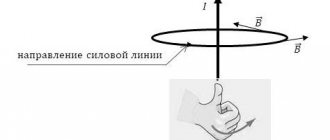
The basis for transmitting electricity by microwaves was the ability of 12 cm waves, with a frequency of 2.45 GHz, to be invisible to the Earth's atmosphere. Such a feature could reduce transmission loss to a minimum. This method requires a transmitter and a receiver. People have long created a transmitter and converter of electrical energy into microwave energy. This invention is called a magnetron. It is included in every microwave oven and is very safe. Problems arose with the invention of the receiver and converter of microwaves back into electricity.
In the 60s of the last century, the Americans invented the rectenna. In other words, a microwave receiver. With the help of the invention, it was possible to transmit 30 kW of electric current over a distance of 1.5 km. At the same time, the loss rate was only 18%. The installation was not capable of more due to the use of semiconductor parts in the receiver device. To receive and transmit more energy power using a rectenna, it would be necessary to create a huge receiving panel. This would increase the energy expended, frequency and wavelength, and therefore the percentage of associated loss. High radiation could kill all living things within a radius of several tens of meters.
In the USSR, a cyclotron converter of microwaves into electricity was invented. It was a 40 cm tube and was completely assembled using lamps. The efficiency of the device was 85%. But for this method, the main disadvantage is the assembly method using lamps. Devices based on such parts can return humanity to the world of huge phones and room-sized computers. You can forget about miniature electrical appliances.
Microwave transmission could be organized from space. A similar project involved collecting solar energy using a satellite and redirecting it to a receiver located on the surface of the Earth. But to do this, you will have to build a satellite with a diameter of a kilometer and a receiver with a diameter of 5 kilometers. You can completely forget about flying within the system's coverage area.
The main problem when transmitting electricity wirelessly is distance and atmospheric refractions. It is also worth considering power. The total power consumption of all electrical appliances in the apartment is 30–40 kW. To provide electricity to one apartment, gigantic structures would have to be built.
Today, the only way to transmit high-power energy is wired. It does not require direct and reverse conversion of electrical energy. It is enough just to apply a high voltage at the beginning and significantly lower it at the end. This method has a number of disadvantages, but remains relevant for many years.
First category of electrical receivers
Today there are three categories of electrical receivers, which differ in the degree of reliability.
The first category of electrical receivers includes those objects where, if the power supply is disrupted, quite serious problems arise. The latter include the following: a threat to human life, severe damage to the national economy, damage to expensive equipment from the main group, massive defective products, destruction of the established technological process for obtaining and distributing electricity, possible disruption of the operation of important elements of public utilities. Such electrical receivers include buildings with large crowds of people, for example, a theater, supermarket, department store, etc. Electrified transport (metro, trolleybus, tram) also belongs to this group.
As for the supply of electricity to these structures, they must be provided with electricity from two sources that are independent of each other. Disconnection of such buildings from the network is allowed only for the period during which the backup power source will be started. In other words, the power distribution system must provide for a quick transition from one source to another in the event of an emergency. In this case, an independent power source is considered to be one on which the voltage will remain even if it disappears on other sources powering the same electrical receiver.
The first category also includes devices that must be powered from three independent sources at once. This is a special group whose work must be ensured uninterrupted. That is, disconnection from the power supply is not allowed even while the emergency source is turned on. Most often, this group includes receivers whose failure entails a threat to human life (explosion, fire, etc.).
Second and third categories of receivers
Electricity distribution systems with the connection of the second category of electrical receivers include such equipment, if the power is turned off, there will be massive downtime of working mechanisms and industrial vehicles, undersupply of products, as well as disruption of the activities of a large number of people living both within the city and outside it. outside. This group of electrical consumers includes residential buildings above the 4th floor, schools and hospitals, power plants, the power outage of which will not result in the failure of expensive equipment, as well as other groups of electrical consumers with a total load of 400 to 10,000 kV.
Energy sources of this category should be two independent stations. In addition, disconnection from the main power source of these objects is allowed until the personnel on duty puts the backup source into operation, or the duty team of workers at the nearest power supply station does this.
As for the third category of receivers, these include all the remaining devices that can be powered by just 1 power source. In addition, such receivers may be disconnected from the network during repairs or replacement of damaged equipment for a period of no more than 24 hours.
Schematic diagram of the supply and distribution of electrical energy
Control of the distribution of electricity and its transmission from source to receiver of the third category within the city is most easily accomplished using a radial dead-end circuit. However, such a circuit has one significant drawback, which is that if any one element of the system fails, all receivers connected to such a circuit will be left without power. This will continue until the damaged section of the chain is replaced. Due to this drawback, it is not recommended to use such a connection scheme.
If we talk about the connection and energy distribution diagram for receivers of the second and third categories, then here you can use a ring circuit diagram. With this connection, if there is a failure in the operation of one of the power lines, you can restore the power supply to all receivers connected to such a network manually by turning off the power from the main source and starting the backup one. The ring circuit differs from the radial circuit in that it has special sections in which disconnectors or switches are located in the off mode. If the main power source is damaged, they can be turned on to restore supply, but from the backup line. This will also serve as a good advantage if any repair work needs to be carried out on the main line. A break in the power supply to such a line is allowed for a period of about two hours. This time is enough to turn off the damaged main power source and connect the backup one to the network so that it distributes electricity.
There is an even more reliable way to connect and distribute energy - this is a circuit with parallel connection of two supply lines or the introduction of automatic connection of a backup source. With such a scheme, the damaged line will be disconnected from the general distribution system using two switches located at each end of the line. In this case, the supply of electricity will be carried out in a still uninterrupted mode, but through the second line. This scheme is relevant for receivers of the second category.
Distribution schemes for the first category of receivers
As for the distribution of energy to power receivers of the first category, in this case it is necessary to connect from two independent power centers simultaneously. In addition, in such schemes, not one distribution point is often used, but two, and a system for automatically turning on backup power is always provided.
For electrical receivers that belong to the first category, automatic switching to backup power is installed on input distribution devices. With this connection system, the distribution of electric current is carried out using two power lines, each of which is characterized by a voltage of up to 1 kV, and is also connected to independent transformers.
Other distribution and power supply schemes for receivers
In order to distribute electricity as efficiently as possible among receivers of the second category, you can use a circuit with maximum current protection of one or two RPs, as well as a circuit with automatic switching on of backup power. However, there is a certain requirement here. These schemes can be used only if the material costs for their arrangement do not increase by more than 5% compared to arranging a manual transition to a backup power source. In addition, such areas must be equipped in such a way that one line can take on the load from the second, taking into account short-term overload. This is necessary, since if one of them fails, the distribution of all voltage will transfer to the remaining one.
There is a fairly common beam connection and distribution scheme. In this case, one distribution point will be powered by two different transformers. A cable is supplied to each of them, the voltage of which does not exceed 1000 V. Each of the transformers is also equipped with one contactor, which is designed to automatically switch the load from one power unit to another if any of them the tension will disappear.
To sum up the reliability of the network, this is one of the most important requirements that must be met so that the distribution of energy is not interrupted. To achieve maximum reliability, you need to not only use the most suitable supply schemes for each category. It is also important to select the correct cable brands, as well as their thickness and cross-section, taking into account their heating and power losses when current flows. It is also important to follow the rules of technical operation and technology for carrying out all electrical installation work.
Based on all of the above, we can conclude that the device for receiving and distributing electricity, as well as supplying it from the source to the final consumer or receiver, is not such a complicated process.