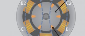
In this article we will cover the topic of mechanical and electrical characteristics of electric motors. Using the example of an asynchronous motor, we will consider such parameters as power, work, efficiency, cosine phi, torque, angular speed, linear speed and frequency. All these characteristics are important when designing equipment in which electric motors serve as drives. Today, asynchronous electric motors are especially widespread in industry, so we will focus on their characteristics. For example, consider AIR80V2U3.
Rated mechanical power of an asynchronous electric motor
The nameplate (nameplate) of the electric motor always indicates the rated mechanical power on the shaft of this motor. This is not the electrical power that this electric motor consumes from the network.
So, for example, for an AIR80V2U3 engine, a rating of 2200 watts corresponds precisely to the mechanical power on the shaft. That is, in optimal operating mode, this engine is capable of performing mechanical work of 2200 joules every second. Let's denote this power as P1 = 2200 W.
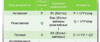
Rated active electrical power of an asynchronous electric motor
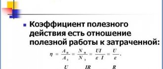
To determine the rated active electrical power of an asynchronous electric motor based on nameplate data, it is necessary to take into account the efficiency. So, for this electric motor the efficiency is 83%.
What does it mean? This means that only part of the active power supplied from the network to the stator windings of the motor, and irreversibly consumed by the motor, is converted into mechanical power on the shaft. Active power is equal to P = P1/efficiency. For our example, from the presented nameplate we see that P1 = 2200, efficiency = 83%. This means P = 2200/0.83 = 2650 W.
Rated apparent electrical power of an asynchronous electric motor
The total electrical power supplied to the stator of an electric motor from the network is always greater than the mechanical power on the shaft and greater than the active power irretrievably consumed by the electric motor.
To find the total power, it is enough to divide the active power by the cosine phi. Thus, the total power is S = P/Cosφ. For our example, P = 2650 W, Cosφ = 0.87. Therefore, the total power S = 2650/0.87 = 3046 VA.
Rated reactive electric power of an asynchronous electric motor
Part of the total power supplied to the stator windings of an asynchronous electric motor is returned to the network. This is the reactive power Q.
Reactive power is related to apparent power via sinφ, and is related to active and apparent power via square root. For our example:
Q = √( 3046 2 – 2650 2 ) = 1502 VAR
Reactive power Q is measured in VAR - in reactive volt-amperes.
Now let's look at the mechanical characteristics of our asynchronous motor: rated operating torque on the shaft, angular speed, linear speed, rotor speed and its relationship with the motor supply frequency.
Rotor speed of an asynchronous electric motor
On the nameplate we see that when powered by alternating current with a frequency of 50 Hz, the motor rotor makes 2870 revolutions per minute at rated load, let’s denote this frequency as n1.
What does it mean? Since the magnetic field in the stator windings is created by an alternating current with a frequency of 50 Hz, then for a motor with one pair of poles (which is AIR80V2U3), the “rotation” frequency of the magnetic field, the synchronous frequency n, turns out to be equal to 3000 revolutions per minute, which is identical to 50 revolutions per second. But since the motor is asynchronous, the rotor rotates with a lag by the slip amount s.
The value of s can be determined by dividing the difference between the synchronous and asynchronous frequencies by the synchronous frequency, and expressing this value as a percentage:
s = ( ( n – n1 )/ n) *100%
For our example, s = ( (3000 – 2870)/3000 ) *100% = 4.3%.
Angular speed of asynchronous motor
Angular velocity ω is expressed in radians per second. To determine the angular velocity, it is enough to convert the rotor speed n1 into revolutions per second (f), and multiply by 2 Pi, since one full revolution is 2 Pi or 2 * 3.14159 radians. For the AIR80V2U3 engine, the asynchronous frequency n1 is 2870 rpm, which corresponds to 2870/60 = 47.833 rpm.
Multiplying by 2 Pi, we have: 47.833*2*3.14159 = 300.543 rad/s. You can convert it to degrees; to do this, substitute 360 degrees instead of 2 Pi, then for our example you get 360 * 47.833 = 17220 degrees per second. However, such calculations are usually carried out in radians per second. Therefore, the angular velocity is ω = 2*Pi*f, where f = n1/60.
Linear speed of an asynchronous electric motor
Linear speed v refers to equipment where an asynchronous motor is installed as a drive. So, if a pulley or, say, an emery disk of known radius R is installed on the motor shaft, then the linear speed of a point on the edge of the pulley or disk can be found by the formula:
Rated torque of asynchronous motor
Each asynchronous electric motor is characterized by a rated torque Mn. Torque M is related to mechanical power P1 through angular velocity as follows:
The torque or moment of force acting at a certain distance from the center of rotation is conserved for the engine, and as the radius increases, the force decreases, and the smaller the radius, the greater the force, because:
So, the larger the radius of the pulley, the less force acts on its edge, and the greatest force acts directly on the electric motor shaft.
For the AIR80V2U3 engine given as an example, the power P1 is equal to 2200 W, and the frequency n1 is equal to 2870 rpm or f = 47.833 rpm. Therefore, the angular velocity is 2*Pi*f, that is, 300.543 rad/s, and the nominal torque Mn is equal to P1/(2*Pi*f). Mn = 2200/(2*3.14159*47.833) = 7.32 N*m.
Thus, based on the data indicated on the nameplate of the asynchronous electric motor, you can find all its main electrical and mechanical parameters.
We hope that this article helped you understand how angular velocity, frequency, torque, active, net and apparent power, as well as the efficiency of an electric motor, are related to each other.
Source: electric.info
Motor rated power
Terms and Definitions.
The wide variety of types and designs of electrical machines and the need for an objective assessment and comparison of their data have led to the need to standardize basic concepts in the field of characteristics, design parameters and operating modes of machines. The terms and definitions of these quantities are established by several GOSTs and are mandatory for use in all types of documentation, textbooks, teaching aids, technical and reference literature. The standards contain more than 200 terms and definitions. This paragraph provides the main ones that apply to all or many types of rotating electrical machines, regardless of their purpose and design. Asynchronous electric motor An asynchronous electric motor is an electrical asynchronous machine for converting electrical energy into mechanical energy. The operating principle of an asynchronous electric motor is based on the interaction of a rotating magnetic field, which arises when a three-phase alternating current passes through the stator windings, with a current induced by the stator field in the rotor windings, resulting in mechanical forces that cause the rotor to rotate in the direction of rotation of the magnetic field. Synchronous electric motor A synchronous electric machine is an electric machine whose rotation speed n (rpm) is connected by a constant ratio with the frequency n = 60 * f / p (where p is the number of pole pairs of the machine) of the alternating current network in which this machine is connected. Synchronous machines serve as alternating current generators; synchronous electric motors are used in all cases where a motor operating at a constant speed is needed; To obtain controlled reactive current, synchronous compensators are installed. DC electric motor Although the modern power supply system is based on the use of alternating current, nevertheless, DC machines are widely used in a wide variety of industries and in everyday life.
Rated engine operating modes
Different operating conditions of production mechanisms determine different operating modes of electric drives.
Therefore, in electrical engineering, the rated modes of electric motors are classified into eight modes with symbols from S1 to S8. S1 - continuous rated operating mode. Corresponds to a mode in which the engine operates with a rated load for so long that the temperature rise of all its parts reaches steady-state values, which must be equal to the permissible ones (Fig. 6.8). Condition τset=τadd
correspond to the engine catalog data
Pн
,
Un
,
In
,
nn
.
Continuous nominal operating mode motors are intended primarily for a wide group of electric drives of continuous action mechanisms.
S2 - short-term rated operating mode. A mode in which periods of rated load alternate with periods of engine shutdown, and during operation the engine does not have time to heat up to the established temperature, but during shutdown it manages to cool down to ambient temperature (Fig. 6.9). As a result, the initial temperature rise at each start-up is zero, and the engine temperature rise achieved at the end of operation is according to (6.35):
determined by the load size, operating time tr
and heating time constant
Tn
.
Thus, the rated power of the short-term mode motor S2 corresponds to a certain rated operating time trn
, the values of which are standardized by values of 15, 30, 60 and 90 minutes.
If the actual operating time is longer than the rated operating time, the motor will reach a temperature higher than the permissible temperature and the load must be reduced to avoid this. Thus, it is impossible to use the engine with the same load in long-term operation, since the steady-state temperature of the engine is
will be greater than the permissible
t o add
(Fig. 6.9).
If the actual operating time is less than the nominal operating time, the motor can be overloaded to the appropriate extent.
Intermittent duty motors are widely used in electric vehicles (doors, unloaders) and for various intermittent auxiliary mechanisms in industry.
S3 - intermittent rated operating mode. A mode in which periods of operation with a rated load alternate with periods of engine shutdown, and during operation the engine does not have time to heat up to the established temperature, and during the pause it does not have time to cool down to ambient temperature (Fig. 6.10).
After a certain number of cycles after switching on, the engine temperature, increasing, will reach a quasi-steady value and will fluctuate around the average value to
.
The maximum temperature rise τmax
should not exceed the permissible value
τadd
.
To make full use of the engine in terms of heating, temperature fluctuations around the average steady-state value should be minimal. This can be achieved if the condition tr
S4 is met - intermittent and short-term nominal mode with frequent starts. This mode is characterized by a significant influence of starting dynamic processes on engine heating. This can happen when the total start-up time per operating cycle is sufficiently large.
S5 - intermittent rated mode with frequent reverses. The operating cycle of an electric drive contains both heavy, long-lasting starting modes and sections with electrical braking.
S6 - intermittent nominal operating mode. It is characterized by alternating periods of engine operation with a rated load with periods of idle operation, and during operation with a load the engine does not have time to heat up to the established maximum temperature, and during idle operation it does not have time to cool down to the established minimum idle temperature. A characteristic of mode S6 is the relative duration of the load:
where tн
and
tхх
– operating times with rated load and idle, respectively.
The cycle duration should not exceed 10 minutes. Nominal values of PN are normalized by values of 15, 25, 40, 60 and 100%.
S7 - intermittent nominal operating mode with frequent reverses. This mode differs from intermittent S5 in that there are no periods of engine shutdown in the operating cycle.
S8 - intermittent nominal operating mode with two or more speeds in the operating cycle. Heavy duty operation, in which there are no periods of engine shutdown, at the same time the engine rotation speed is regulated (accordingly, there are starting and braking modes). This operating mode characterizes the feed drives of metal-cutting machines with an automated work cycle in the manufacture of complex products.
Thus, the nominal modes S4÷S8 complement specific information about intensive intermittent modes and long-term modes with variable cyclic load.
What is rated power?
We come across the term “rated power” almost every day. Whether we choose an electric kettle or an incandescent lamp, this value is indicated everywhere. The unit of measurement is watts or kilowatts. It would seem - what could be simpler in this matter? After all, even from a school physics course, everyone knows that to determine power (P) it is enough to multiply the values of current and voltage. But what is hidden behind the words “rated power”? The term “nominal” refers to a certain value of something that does not take into account external corrective factors. Thus, the rated power is the value specified by the manufacturer, which can only be obtained with the specified design parameters. This is a general concept. In each specific case, it is necessary to take into account its specific features. Let's take an example with an incandescent lamp. Its glass bulb is marked: 230 V, 100 W. That is, 100 W can only be achieved at a voltage of 230 V. The rated power is those same 100 W. Its value decreases with decreasing voltage and increases with increasing voltage since these parameters are directly dependent on each other (P=I*U).
Rotor speed
To calculate this parameter of electric motors, we need the AC frequency and the number of revolutions per minute at the optimal load. Let the nameplate indicate the following data: the current frequency is 50 Hz, and the number of revolutions is 2800.
Alternating current creates a magnetic field that has a frequency of 50*60=3000 revolutions per second. It is known that the electric motor is asynchronous, which means that there is a lag from the rated speed by a certain amount. Let's call it sliding and denote it by s.
The amount of slip is determined by the following formula: s = ((3000 – 2800) / 3000) * 100% = 6.7%.
Selecting a generator by power
When choosing a generator, the consumer pays attention to various installation parameters - weight, service life, mobility, availability of additional functionality, price, etc. But first of all, you need to choose an installation based on its power. How to correctly calculate this indicator and what to pay attention to?
To make it clearer, let's look at this situation using a simple example. Let's say we have the following household appliances: a vacuum cleaner, a heater, a freezer. The power of these household appliances is 1 kW, 2 kW and 0.3 kW, respectively. It turns out that in order to ensure the operation of these devices, we need a generator with a power of at least 3 kW. To understand this, let's understand the concept of rated power of the generator.
The nominal, or, as it is also called, the real power of the installation, differs significantly from the maximum. In technical documentation, manufacturers most often indicate the maximum power ratings for a given generator model. It is worth noting that with such a load the installation can operate for a very short time without critical consequences - in some cases it is seconds, sometimes 1-2 minutes. At the same time, the real or rated power is slightly lower than the maximum. To calculate it, the power factor cos φ is required. This indicator is determined by the ratio of active power to total power.
Linear speed
This mechanical parameter characterizes the equipment that uses this asynchronous motor. Let us assume that a disk of a certain radius R is attached to the motor shaft. In this case, the linear speed can be determined by the following formula:
- Linear speed = Angular speed * R.
- Let's calculate the linear speed for our example. Let's take R = 0.3 m.
- Linear speed = 293.276 * 0.3 = 87.9828 m/s.
Example
Let's say we have a generator with a power rating of 3 kVA and cos φ equal to 0.8. In this case, the rated power of this installation will be equal to:
3 kVA x 0.8=2.4 (kW)
Now you can understand why power can be indicated in certain units of measurement, in watts (W) or Volt Amperes (VA). Some manufacturers, in order to save the consumer from the need to carry out calculations, simply indicate in the accompanying documentation both power values - nominal and maximum. There are also options when the manufacturer indicates only one of the capacities and gives the value of the power factor. Some unscrupulous companies may hide the power factor from the consumer. This is done in order to pass off the generator as a more powerful unit than it actually is.
Maximum permissible boat motor power
The American BIA standard determines the maximum safe outboard motor power for a boat by multiplying its length by the width of the transom.
| Power (hp) | 3 | 5 | 7,5 | 10 | 15 | 20 | 25 | 30 | 40 | 50 | 60 |
| Length*Dance width (sq.m.) | 3,25 | 3,5 | 3,8 | 4,1 | 4,4 | 4,8 | 5,2 | 6,4 | 7,0 | 7,5 | 8,0 |
True, some adjustment is needed here. If the boat is narrow and rather flat-bottomed (like the first Kazankas), then such a calculated power will not be entirely safe, especially when operated by an inexperienced skipper. In this situation, it is recommended to divide the resulting power after calculations by 2. Even this power will be quite enough to get the boat into planing mode, and the boat will be quite safe.
Source
Taking into account the type of load
Household electrical appliances are characterized by two types of load:
The active (ohmic) load is consumed by devices that convert the received energy into heat. This is an electric stove, iron, hair dryer, air heaters, etc. The reactive load is consumed by other electrical appliances, which convert only a small portion of the energy into heat. The bulk of the energy consumed is used for another purpose. Examples of such appliances include a refrigerator, vacuum cleaner, TV, computer, etc.
If you need help choosing the generator power for your home, industrial workshop or any other facility, contact our specialists for qualified advice.
Source: www.tecnuvo.ru
Engine types
DC and AC motors
Depending on the electric current used, motors are divided into two groups:
- DC drives;
- AC drives.
DC motors are not used as often today as they used to be. They have practically been replaced by asynchronous motors with squirrel-cage rotors.
The main disadvantage of DC electric motors is that they can only be operated with a DC source or an AC-to-DC converter. In modern industrial production, ensuring this condition requires additional financial costs.
However, with significant disadvantages, this type of motor is characterized by a high starting torque and stable operation under conditions of high overloads. Drives of this type are most often used in metallurgy and machine tool construction and are installed on electric vehicles.
The operating principle of AC electric motors is based on electromagnetic induction that occurs during the movement of a conducting medium in a magnetic field. To create a magnetic field, windings flowing around currents or permanent magnets are used.
AC electric motors are divided into synchronous and asynchronous. Each subgroup has its own design and operational features.
Synchronous electric motors
Synchronous motors are the optimal solution for equipment with constant operating speed: DC generators, compressors, pumps, etc.
The technical characteristics of synchronous electric motors of different models differ. The rotation speed ranges from 125 to 1000 rpm, the power can reach 10 thousand kW.
The design of the drives includes a short-circuited winding on the rotor. Its presence allows for asynchronous engine starting. The advantages of equipment of this type include high efficiency and small dimensions. The operation of synchronous electric motors allows you to reduce electricity losses in the network to a minimum.
Asynchronous electric motors
Asynchronous AC motors are most widely used in industrial production. A feature of these drives is a higher frequency of rotation of the magnetic field compared to the speed of rotation of the rotor.
Modern engines use aluminum to make the rotor. The light weight of this material makes it possible to reduce the weight of the electric motor and reduce the cost of its production.
The efficiency of an asynchronous motor drops almost by half when operating at low loads - up to 30-50 percent of the nominal value. Another disadvantage of such electric drives is that the starting current parameters are almost three times higher than the operating parameters. To reduce the starting current of an asynchronous motor, frequency converters or soft starters are used.
Asynchronous motors meet the requirements of various industrial applications:
- For elevators and other equipment requiring stepwise speed changes, multi-speed asynchronous drives are produced.
- When operating winches and metalworking machines, electric motors with an electromagnetic braking system are used. This is due to the need to stop the drive and fix the shaft in case of power outages or disappearance.
- In processes with a pulsating load or in intermittent modes, asynchronous electric motors with increased sliding parameters can be used.
Valve motors
The group of valve electric motors includes drives in which the operating mode is controlled by means of valve converters.
The advantages of this equipment include:
- High service life.
- Easy maintenance due to contactless control.
- High overload capacity, which is five times the starting torque.
- Wide speed control range, which is almost twice the range of asynchronous electric motors.
- High efficiency at any load - more than 90 percent.
- Small dimensions.
- Fast payback.
motor rated power
3.13 motor rated power
: Net mechanical power at the shaft, expressed in watts (W) or kilowatts (kW).
See also related terms:
Rated power of the electric motor(s)
Rated power of the electric motor(s)
Dictionary-reference book of terms of normative and technical documentation. academic.ru. 2015.
See what “rated motor power” is in other dictionaries:
Rated power of the electric motor (motors) - 1.7 According to GOST 10512 78 Source... Dictionary of terms of normative and technical documentation
Rated power - 4a. Rated current of the lighting device Current indicated by the manufacturer on the lighting device Source: GOST 16703 79: Lighting devices and complexes. Terms and definitions original document... Dictionary-reference book of terms of normative and technical documentation
Electrical power - Electrical power is a physical quantity that characterizes the speed of transmission or conversion of electrical energy. Contents 1 Instantaneous electrical power ... Wikipedia
STO 70238424.29.160.30.002-2009: Electric motors. Organization of operation and maintenance. Standards and requirements - Terminology STO 70238424.29.160.30.002 2009: Electric motors. Organization of operation and maintenance. Standards and requirements: 3.1 asynchronous start of a rotating AC motor: Starting a rotating electric motor... ... Dictionary of terms of normative and technical documentation
1: — Terminology 1: : dw Number of the day of the week. “1” corresponds to Monday Definitions of the term from various documents: dw DUT The difference between Moscow and UTC time, expressed by an integer number of hours Definitions of the term from... ... Dictionary-reference book of terms of normative and technical documentation
Rated torque
A parameter such as the torque of an electric motor shows how the mechanical power of a device depends on the angular velocity. This relationship is illustrated by a simple relationship: torque is the ratio of power to angular velocity.
There is also a relationship between torque and pulley radius: Torque = Force * Radius.
This equality suggests that the force increases at a smaller radius of rotation, and vice versa. That is, when designing a device with an asynchronous motor, one should take into account the fact that the acting force increases as it approaches the shaft axis. In some cases, this feature can play an important role.
Thus, to calculate all the necessary electrical and mechanical characteristics of the electric motor, it is enough to know the data indicated on the nameplate or, in other words, the nameplate. Simple formulas will help you correctly configure the operation of electrical equipment and optimally use production resources.
Connecting an electric motor - basic diagrams, methods and features of connecting various models (instructions + photos)Single-phase electric motor: main types, principle of operation and instructions for connection and configuration. Review of the best manufacturers!
Rewinding electric motors: step-by-step instructions for repairing and restoring the motor winding with your own hands (instructions with photos and videos)
Types of electric motors
The most common is the three-phase asynchronous electric motor. DC and synchronous electric motors are rarely used.
Most electrified machines require a drive with a power of 0.1 to 10 kW, a much smaller part requires a drive with a power of several tens of kW. As a rule, squirrel-cage three-phase electric motors are used to drive working machines. Compared to a phase motor, such an electric motor has a simpler design, lower cost, greater operational reliability and ease of maintenance, slightly higher performance indicators (power factor and efficiency), and requires simple equipment for automatic control. The disadvantage of squirrel-cage electric motors is the relatively high starting current. When the power of the transformer substation and the electric motor are commensurate, its start-up is accompanied by a noticeable decrease in the network voltage, which complicates both the start-up of the motor itself and the operation of neighboring pantographs.
Along with three-phase asynchronous squirrel-cage electric motors of the basic design, separate modifications of these motors are also used: with increased slip, multi-speed, with a wound rotor, with a massive rotor, etc. Electric motors with a wound rotor are also used in cases where the power of the supply network is insufficient for starting motor with a squirrel-cage rotor.
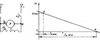
The mechanical characteristics of asynchronous electric motors with a squirrel-cage rotor largely depend on the shape and size of the rotor slots, as well as on the method of making the rotor winding. According to these signs
Rice. 1. Torque curves M = f(S) of asynchronous electric motors
There are electric motors with a normal rotor (normal squirrel cage), with a deep groove and with two cages on the rotor. The rotor design of general-purpose squirrel-cage asynchronous electric motors with a power of over 500 W predetermines the phenomenon of current displacement in the winding, which is equivalent to an increase in its active resistance. Therefore, and also due to the saturation of the magnetic paths of dissipation fluxes, such electric motors (primarily the rotor windings) have variable parameters and the analytical expressions of their mechanical characteristics become more complicated. An increase in the active resistance of the rotor during the starting period causes an increase in the initial starting torque with a slight decrease in the strength of the initial starting current (Fig. 1).
Correct motor and frequency converter power
Manufacturers of electric motors and frequency converters have developed various methods for quickly selecting the power of motors and frequency converters for a specific equipment load. The same basic procedure is used by most engineering applications. However, it is important for engineers to clearly understand the selection procedure.
One of the best procedures uses simple numbering based on load limit curves to make the basic engine power selection. This procedure is described below. Other factors are then checked to ensure the optimal motor and converter combination.
The following 4 selection principles are recommended:
Selection principle 1:
First, the base speed should be selected so that the motor runs as fast as possible, slightly above the base speed of 50 Hz.
This is desirable because:
- Motor thermal performance improves at f ≥ 50 Hz due to more efficient cooling at higher speeds.
- The converter's switching losses are minimal when it operates in the field weakening range above 50 Hz.
- At constant torque load, a larger speed range is achieved when the motor operates well in the field weakening range at maximum speed. This means that the torque and speed of a variable speed drive are used most efficiently.
Typical torque and power curves with constant power/torque drive
This could mean cost savings in the form of a smaller motor and converter.
Although many manufacturers claim that their converters can produce output frequencies up to 400 Hz, these high frequencies are rarely used except in special (and unusual) applications. The design of standard frame motors and the reduction in peak torque in the field weakening region limit their use at frequencies above 100 Hz.
The maximum speed at which a standard squirrel cage motor can start should always be checked with the manufacturer, especially for larger 2-pole (3000 rpm) motors over 200 kW. The fan noise generated by the engine also increases significantly as the engine speed increases.
A comparison of the torque produced by 4-pole and 6-pole motors is shown in Figure 1. This illustrates the higher torque capacity of a 6-pole machine.
Comparison of thermal power limit curves for two 90 kW squirrel cage motors
a) 90 kW 4-pole motor (1475 rpm)
b) 90 kW 6-pole motor (985 rpm)
Selection principle 2:
Selecting a larger motor simply to be "safe" is usually not recommended because it means that a converter with a larger frequency range must also be selected. Frequency converters, in particular the PWM type, are designed for a maximum peak current value, which is the sum of the fundamental and harmonic currents in the motor.
The larger the motor, the greater the peak currents.
To avoid this peak current exceeding the design limit, the converter should never be used with a motor size larger than the specified one. Even when a large motor is lightly loaded, its harmonic current peaks are high.
Selection principle 3:
Once the motor has been selected, it is fairly easy to select the correct converter size from the manufacturer's catalog. They are usually rated for current (not kW) based on a specific voltage. This should be used as a guide only as converters should always be selected based on the maximum continuous motor current.
Although most catalogs are based on standard IEC motor power ratings (kW), motors from different manufacturers have slightly different current ratings.
Variations of electric motors according to climate control
When selecting an electric motor, you need to know what climatic conditions this motor will be used in.
The designations for different climate versions are listed below:
- U – Temperate climate;
- HL - Cold climate;
- TC – Tropical Dry climate;
- TV – Tropical Humid Climate;
- T – Tropical climate (generalized);
- M – Maritime climate;
The digital value after the letter designation of the brand indicates the type of its placement:
- 1 – work on the “street”;
- 2 – work on the “street”, but under a canopy;
- 3 – work indoors;