Principle of operation
In the vast majority of cases, mains-powered adapters operate using a pulse circuit. This allows you to obtain lightweight, compact, economical devices. You have to pay for this with complicated circuitry and reduced reliability compared to transformer power supplies.
Most network chargers have the same structure:
- rectifier with filter;
- pulse generator;
- inverter;
- pulse transformer;
- secondary rectifier with filter;
- indication circuits;
- stabilization circuits (may be absent).
The rectifier is often made using a half-wave circuit - the power consumption of the charger is low, so this is sufficient. For the same reason, the capacity of the smoothing capacitor is small. The pulse generator is often circuitously combined with an inverter - the same transistor generates oscillations and switches the winding. But sometimes this unit is also built on a specialized microcircuit. The secondary rectifier is also usually half-wave to avoid unnecessary voltage drop across the diodes. Schottky diodes are used for the same purpose. In most cases, the indication circuits are an LED with a resistor.
Stabilization is carried out using pulse width modulation through feedback. In many schemes, an optocoupler is used to organize it. This ensures galvanic isolation of the output from the high-voltage part.
Cable
The cable comes in several types:
- direct - a cheap and simple option, but not very convenient;
- twisted - rolled into a spring, such a cable is more compact in the absence of tension;
- in the form of a tape measure - takes up minimal space;
- built-in - attached to the charger body and located in a special niche. Although this cable is relatively small, it is more convenient than other analogues, since it will not get lost.
The cable length varies: less than 50 cm, 50-100 cm, 100-200 cm. It is determined by the distance from the power source to the charger. A cable that is too short or too long will create inconvenience when operating the charger. In most cases, a length of 50-100 cm will be sufficient. For ASU, a length of less than 50 cm is suitable.
Important: pay attention to the quality of the cable, as it affects the charging speed of the gadget. A good cable should not allow any drop in output current or voltage. Also, the low charging speed can be explained by the long length or small cross-section of the cable.
Charging circuits for mobile phones
Since the process of replenishing the battery with energy is monitored by the phone’s built-in controller, power adapters for mobile phones are made according to a fairly simple scheme. Some of them even have an unstabilized output.
Scheme of an unstabilized network adapter YL-0061.
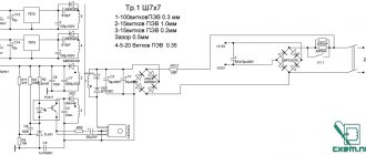
The mains voltage is rectified by diode VD1 and filtered by capacitor C1. A self-oscillator is assembled on transistor VT1, which “cuts” pulses from a constant voltage that are fed to the primary winding of the pulse transformer TV1. The pulses transformed into the secondary winding are rectified by diode VD5, the voltage is filtered by capacitance C5 and supplied to the consumer. LED VD6 serves to indicate the presence of voltage at the output. Since the output level of this adapter is not stabilized, the voltage will vary depending on the load current.
Circuit diagram of a Chinese network charger with output voltage stabilization.
Another charging circuit for a phone has output voltage stabilization circuits. The input elements, generator, pulse transformer and secondary rectifier are constructed similarly to the previous version. Stabilization is carried out through feedback performed on optocoupler U1. The higher the output voltage, the higher the current through the optocoupler LED, the more the optocoupler receiving transistor opens.
In this way, the bias voltage at the base of transistor VT1 changes and the duration of the generated pulses decreases. When the output level decreases, the reverse process occurs, leading to an increase in the pulse duration.
Car charger circuit diagram.
Power supplies designed for charging phones from the car's electrical system are even simpler - they do not have a converter part. They consist of a stabilizer, which is often built according to a linear circuit, and a filter.
Fast charge
Makes it possible to significantly reduce charging time. Involves charging at higher current and voltage levels compared to standard mode. In this case, the charger and the device connected to it must support charging technology and the corresponding current and voltage parameters.
Quick Charge, developed by Qualcomm, is the most common standard used in Android smartphones. Other fast charging standards: TurboPower (Lenovo, Motorola), Adaptive Fast Charging (Samsung), Power Delivery (Apple), Super Charge (Huawei), Pump Express (MediaTek), Super mCharge (Meizu), VOOC Flash Charging (OPPO), Dash Charge (One Plus).
Fast charging standards parameters (voltage and power):
- Quick Charge 2.0 – 5V, 9V, 12V and 20V, up to 15 W;
- Quick Charge 3.0 –3.2-20V (0.2 V steps), up to 15 W;
- Quick Charge 4.0 – 5-24V, up to 15W;
- TurboPower – 5V, 9V and 12V, 25.8 W;
- Adaptive Fast Charging – 5V and 9V, 15 W;
- Power Delivery – 5V, 12V and 20V, 100 W;
- Super Charge – 5V, 22.5 W;
- Pump Express – 9V and 12V, up to 18 W;
- Super mCharge – 11V, 55 W;
- VOOC Flash Charging – 5V, 25W;
- Dash Charge – 5V, 20W.
To date, there is no consensus on how harmful fast charging is. Some users claim that this mode has almost no effect on battery wear, while others do not agree with this point of view. In any case, it is not recommended to use fast charging very often.
How to disassemble a phone charger
Some charger housings are assembled with screws or self-tapping screws. But many inexpensive devices are encased in a shell that is simply glued together.
Cutting the adhesive joint.
If it becomes necessary to disassemble such an adapter, it will have to be cut along the seam. This can be done using a knife or other sharp tool. When cutting the body, it is necessary to take precautions so that the knife does not slip and cause injury. You also need to be careful not to damage the internal contents during the process.
Adapter housing with cover removed.
If you need to reassemble the device after repair, it will have to be glued together. This can be done with dichloroethane or other adhesive. As a last resort, you can wrap the case with insulating tape, sacrificing aesthetics.
Video example of opening the original Samsung ETA-U90E charger.
Wireless car
This charger is a holder that securely holds the smartphone and prevents it from falling while the car is moving. This memory makes it possible to use a smartphone as a navigator.
Methods for attaching a wireless charger:
- sticker – provides reliable fixation of the charger, but is designed for one-time use;
- a clothespin holder in the air duct is a reliable and simple method of fastening, it can be used multiple times, this option is most common;
- suction cup holder for windshield, dashboard - can be used an unlimited number of times, but is not suitable for attaching the charger to a textured surface.
Methods for attaching a smartphone to the ASU:
- mechanical (manual) clamp - a cheap and simple option, ensures compatibility with many device models;
- gravity clamp - compares favorably with the previous method with greater reliability and ease of operation;
- magnet is a reliable option, compatible with models of different sizes, but not suitable for devices that are too heavy;
- sensor clip – reacts to the approach of a person’s hand or portable device. The most convenient way to mount your smartphone. Cons: high price, dependence on nutrition.
Basic faults and repairs
The main malfunctions include problems with the power connector, cord and electronic components. For each type of repair you need to have your own skill level, set of tools and equipment.
How to replace the connector yourself
During operation, the power connectors of the adapters become mechanically loose. The charging process turns into torture or becomes impossible. It is not difficult to replace the connector with your own hands, with a minimum of skills.
| Sequencing | Photo | Important Note |
| 1. First you need to find the same connector. It can be taken from the donor charger. Also, replacing the connector may be necessary if you have a working charger from a similar phone, but with a different connector. | Connector to replace from another adapter. | When installing a connector to another adapter, you need to make sure that the charger and the phone match the supply voltage and the charger can supply the required current. |
| 2. Typically, such connectors on finished chargers have a non-separable design. The unnecessary connector must be cut off with a knife or scissors with a 10-15 cm piece of wire to make it more convenient to work. | A connector cut off from the charger. | |
| 3. The next step is to clean the wires. This is done with a knife or a special insulation stripper. | Stripped wires before connection. | |
| 4. Next, the conductors need to be twisted and the twisted points soldered. Without soldering, the connection strength will be insufficient. | Twisted conductors. | Before connecting conductors, you must ensure correct polarity. Reversing the polarity may damage the phone . |
| 5. Each conductor must be insulated individually. This can be done with insulating tape or heat shrink tubing. | Insulate the joint with electrical tape. | |
| 6. Next, it is advisable to apply general insulation. | Charger ready to use. |
This completes the replacement process and the device is ready for use. You can charge your phone.
If a donor adapter is not available, a suitable connector can be purchased at a specialty store or on the Internet. The old connector must be cut off in the same way, and the new one must be soldered, strictly observing the polarity.
How to repair a charging cable
During operation, the cable conductor may break inside the insulation. The wire breaks due to repeated kinks during use. This usually happens at the outlet of the adapter box or near the connector, but failure is also possible in any other place - it depends on how the device is handled.
You can find the location of the damage using a tester and a needle. One probe of the device is connected to the power connector, and a needle is connected to the second. With its help, the insulation is pierced in different places of the cable and the place where the contact disappears is found.
Finding the fault location in the power cable.
At the break point, the cable must be cut, the wires must be stripped, the conductors soldered and insulated, as in the previous paragraph.
Repairing a broken wire.
Video process of repairing the charging cable.
Simple repair of the charger unit
To carry out the simplest repair of a mobile phone charger related to electronic components, you need to have at least a tester, and even better, an oscilloscope. It is convenient if there is a circuit diagram for a specific adapter, but you can do without it. First you need to inspect the board for the presence of charred elements or swollen oxide capacitors.
If everything is visually in order, you can use a tester to check the voltage on the filter capacitor. It is located next to the diode, on the input side from the network.
Elements of the network power supply.
In the example given, the voltage can be measured across two capacitors 1 and 2 - here the input filter is built according to a U-shaped circuit with a choke. The voltage should be approximately the same - at least 220 VDC, depending on the load. If it is significantly less, we can assume a malfunction of the diodes of the high-voltage rectifier 3 , 4 , 5 , 6 (here the full-wave bridge rectifier) or other elements of the input part - resistor 7 or inductor 8 .
If everything is in order, you need to measure the voltage at the output capacitor 9 . It should be approximately equal to the output rating. If the voltage is significantly lower, failure of the secondary rectifier diode 10 . If noticeably higher, feedback optocoupler 11 . If these elements are working properly, you need to check for the presence of pulses at the terminals of the master oscillator transistor 12 . For this you will need an oscilloscope. If there are no pulses, you need to unsolder the transistor and ring it. If it is in order, you need to check the remaining elements of the high side one by one. If everything is OK here, we can assume a break in the windings of the pulse transformer 13 . They need to be tested with a tester - the resistance should be close to zero or no more than a few ohms.
For clarity, we recommend viewing it.
Purpose
For phones, smartphones – equipped with one USB output for connecting relevant equipment. The output current is 1 A.
For tablets – equipped with one output for connecting a tablet. Output current – 2.1 A.
Important: the maximum current of 2.1 A is released only when one device is connected. If two devices are charging at the same time, the charger will “give” a current of 1 A. If you charge equipment rated for 2.1 A using a 1 A charger, it will take longer to charge.
Universal – compatible with smartphones, tablets, wireless headphones, e-readers, fitness bracelets and other portable equipment. Such models are equipped with several USB outputs for charging gadgets from one outlet. A good choice for those who travel frequently: you don’t have to take a charger with you for each device, but get by with one charger and a set of cables.
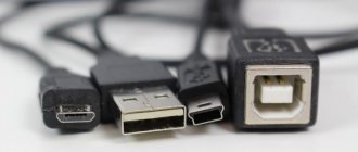
Universal chargers also include USB charging with multiple plugs. One end of the cable is connected (via a USB port) to a computer, laptop, or charger, and the other (via connectors) is connected to a gadget that needs to be recharged.
USB charging powers phones and smartphones of different brands, tablets, and cameras. Such a device is inexpensive, but its functionality is limited by the presence or absence of a computer, laptop, or ASD at hand.
Important: when using universal USB charging, you must take into account the input current parameter - the current in the devices from which the device is charged. This characteristic affects how quickly the connected device's battery charges. But not all power sources provide high current. For example, a PC USB port has an input current of 500 mA.
For smart watches - such chargers are mainly wireless and are made in the form of a round platform with a cable/USB connector for connecting to a device with such a connector.
Important: wrist devices use different charging technologies. Therefore, when purchasing a charger, pay attention to its compatibility with your smartwatch model.
Standalone PowerBanks for phones
In what cases is it better to buy a new adapter?
The main situation when it is better not to try to repair the network adapter, but to purchase a new one, is if it becomes clear that even if functionality is restored, it will not be possible to fully ensure safe operation. If the housing or protective insulation is damaged and accidental contact with live parts is possible.
Of course, it is better to purchase a new device if you are not sure of the final result - you do not have enough qualifications to repair it or there are no spare parts. In general, repairing an adapter for phones is not economically feasible, so it is more rational to buy a new one in any case, unless the fault is clearly expressed (it takes most of the time to find it). And, of course, if it is impossible to buy a new adapter. This applies, for the most part, to old phones - new gadgets are equipped with standard USB type C connectors, and purchasing such a charger (or a separate cord) is not difficult.
