Zero carries current - this means that the PEN conductor, which has a common point with the neutral of the transformer and the ground, in certain situations may have a potential different from zero.
The most common reason why the neutral is electrocuted is a break (burnout) of the transformer neutral. In this case, phase voltage appears on the PEN conductor, which is no longer connected to the neutral and ground, depending on the uneven load.
Also, a non-zero potential on the neutral wire is almost always present during normal operation. In a five-wire power supply system, there is no voltage between ground and neutral only at the point where these wires connect. As you move away from this place, due to the resistance of the wires, the potential difference gradually appears and increases. This review will examine in detail exactly this situation, when the zero is electrocuted in the normal operating mode of the power supply system.
Differences between phase and neutral wires
The phase wire (phase) is designed to supply electricity to the consumer.
The purpose of the neutral wire (neutral or zero) is to equalize voltage asymmetry at different load values in the phases.
It is connected to the zero points of the source and consumer when they are connected into a “star”.
Connecting a neutral wire (three-phase four-wire network) is only possible if the source and load are connected in a star.
When connecting in a “triangle”, there is no need for it, since the linear and phase voltages in the phases are the same.
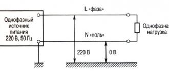
To understand the difference between line and phase voltage, it is necessary to understand that in a three-phase three-wire circuit, the linear (voltage between the two phase wires) is generally 380 V, and the phase - the voltage between phase and neutral - is √3 times less than approximately 220 V.
The neutral wire earned its name because when the devices are operating, the current in it, with the same load of the three phases, is zero. Its resistance is low. Therefore, if one or more phases are overloaded, the current in it will quickly increase. In the lighting scheme, its presence is a prerequisite. Otherwise, uniformity of illumination is not guaranteed .
Depending on the role, the neutral wire can be working, protective, or combined.
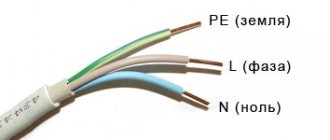
A worker is designated by the Latin letter N and is colored blue in European countries. In some other countries the color may be gray or white.
Protective is designated PE. It is designed for safety in case of potential contact with the body of the electrical appliance. In normal mode, it is de-energized, and if it breaks down, it is a conductor that will divert dangerous potential from the electrical appliance to the ground. The color of this vein is yellow-green.
In some systems, the neutral wire is combined with the protective wire . In this case, the marking will be designated as PEN and the color of this core will be blue with yellow-green stripes at the ends.
Home electrical wiring: finding zero and phase
You can determine at home where which wire is located in different ways. We will analyze only the most common ones that are accessible to almost anyone: using an ordinary light bulb, an indicator screwdriver and a tester (multimeter).
About the color marking of phase, neutral and ground wires in the video:
Checking with an electric lamp
Before you begin such a test, you need to assemble a testing device using a light bulb. To do this, it should be screwed into a cartridge of suitable diameter, and then secured to the wire terminal, removing the insulation from their ends with a stripper or an ordinary knife. Then the lamp conductors must be applied one at a time to the cores being tested. When the lamp lights up, it will mean that you have found a phase wire. If you check a cable with two cores, it is already clear that the second one will be zero.
Checking with an indicator screwdriver
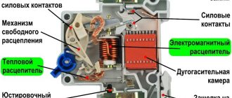
A good assistant in work related to electrical installation is an indicator screwdriver. The operation of this inexpensive instrument is based on the principle of capacitive current flowing through the indicator body. It consists of the following main elements:
- A metal tip shaped like a flathead screwdriver that is applied to wires for testing.
- A neon light bulb that lights up when current passes through it, thus signaling phase potential.
- A resistor to limit the amount of electrical current that protects the device from combustion under the influence of a powerful flow of electrons.
- A contact pad that allows you to create a circuit when you touch it.
Professional electricians use more expensive LED indicators with two built-in batteries in their work, but a simple device made in China is quite accessible to anyone and should be available to every home owner.
If you check the presence of voltage on the wire using this device in daylight, you will have to look more closely during the work, since the glow of the signal lamp will be difficult to see.
When the screwdriver tip touches the phase contact, the indicator lights up. In this case, it should not light up either at the protective zero or at the grounding, otherwise we can conclude that there are problems in the connection diagram.
When using this indicator, be careful not to accidentally touch a live wire with your hand.
About determining the phase clearly in the video:
Checking with a multimeter
To determine the phase using a home tester, you need to put the device in voltmeter mode and measure the voltage between the contacts in pairs. Between the phase and any other wire, this indicator should be 220 V, and applying probes to the ground and protective zero should show the absence of voltage.
Features of the neutral wire
The neutral wire prevents undesirable situations during emergency operation. Without it, in the event of a phase short circuit of two phases, the voltage in the third phase will instantly increase by √3 times. This will have a detrimental effect on the equipment that powers this source. If there is a zero in this situation, the voltage will not change.
If one of the phases in a three-phase three-wire system (without zero) breaks, the voltage on the two remaining phases will decrease. They will be connected in series, and with this type of connection the voltage is distributed among consumers depending on their resistance.
If one of the phases in a three-phase four-wire system breaks , the voltage in the two remaining phases will not change its value.
Fuses are not installed in the neutral wire due to its great importance, because its breakage is undesirable
Since most of the time electrical installations operate, the current in this wire is either zero or insignificant, there is no point in making it the same cross-section as the phase wire cross-section. Most often, for reasons of economy, it has a smaller cross-section of the conductor than the cross-section of the conductors of the phases in one electrical installation. If the protective wire is not combined with the neutral wire, its cross-section is half that of the phase wire.
Induced currents
Everything works fine, but the indicator detects voltage on each pin of the plug connector. Moreover: the device shows two phases in the socket when the power supply to the entire apartment is turned off. This completely unrealistic situation can happen if a high-voltage power line runs near your home.
The information posted on this page is for informational purposes only. We recommend that all electrical work be carried out by a professional electrician.
This is the so-called pickup or, to put it more correctly, induced voltage. Even experienced electricians can get confused here. Work in this case is associated with a high risk of electric shock, so only professionals should perform it.
Classification of power line neutrals
The purpose of power lines is very diverse. There is also a variety of equipment to protect them from leaks and short circuits. In this regard, neutrals are classified into three types:
- solidly grounded;
- isolated;
- effectively grounded.
If the power line with voltage from 0.38 kV to 35 kV is short and the number of connected consumers is large, then a solidly grounded neutral is used. Consumers of a three-phase load receive power thanks to three phases and zero, and consumers of a single-phase load receive power from one of the phases and zero.
With an average length of power lines with voltages from 2 kV to 35 kV and a small number of consumers connected to this line, insulated neutrals are used. They are widely used for connecting transformer substations in populated areas, as well as powerful electrical equipment in industry.
In networks with a voltage of 110 kV and higher, with a large length of power lines, an effectively grounded neutral is used.
Household electrical wiring.
Initially, electricity is generated at a power plant. Then, through the industrial power grid, it enters the transformer substation, where the voltage is converted to 380 volts. The connection of the secondary windings of the step-down transformer is made according to the “star” circuit: three contacts are connected to the common point “0”, and the remaining three are connected to terminals “A”, “B” and “C”, respectively. For clarity, a picture is provided.
The combined contacts “0” are connected to the grounding loop of the substation. Also here the zero is split into:
- Working zero (shown in blue in the picture)
- PE conductor performing a protective function (yellow-green line)
The zeros and phases of the current from the output of the step-down transformer are supplied to the distribution panel of the residential building. The resulting three-phase system is distributed across panels in the entrances. Ultimately, a phase voltage of 220 V and a PE conductor, which performs a protective function, enters the apartment.
So, what is current nophase? A zero is a current conductor connected to the ground loop of a step-down transformer and serves to create a load from the current phase connected to the opposite end of the transformer winding. In addition, there is a so-called “protective zero” - this is the PE contact described earlier. It serves to drain current when a technical malfunction occurs in the circuit.
This method of connecting residential buildings to the city power grid has been proven for decades, but it is still not ideal. Sometimes malfunctions appear in the above system. Most often, they are associated with poor connection quality in a certain section of the circuit or a complete break in the electrical wire.
Reaction of electrical appliances to zero loss
If the common neutral wire in a multi-story building breaks, consumers will feel it as a result of a voltage surge in their electrical appliances.
The main factors that can lead to loss of power to the common zero:
- emergency situation at the substation;
- outdated wiring;
- The wiring installation was not done very well.
The phase to which more consumers of the apartment building are connected will be overloaded. The tension in it will decrease. In the phase to which the least number of consumers are connected, the voltage will increase sharply.
This will have a negative impact on the devices - a decrease in voltage will cause them to operate ineffectively, and an increase in voltage may lead to the failure of those that are currently connected. To protect yourself from such a situation, you need to install an individual surge suppressor in the panel that supplies a separate apartment. As soon as the voltage begins to exceed permissible values, the limiter will quickly turn off the power.
If a zero break occurs directly in the apartment, the electricity will be lost completely, but at the same time the phase will not be turned off. The danger is that it can go right to the neutral wire. And if any electrical device was previously grounded to it, the body of this electrical device will be energized, or, more simply put, it will begin to “beat with current.”
Let's delve into the topic
Consumers are powered from the low voltage windings of a step-down transformer, which is the most important component of the operation of a transformer substation. The connection between the substation and subscribers is as follows: a common conductor is supplied to the consumers, extending from the point of connection of the transformer windings, called the neutral, along with three conductors, which are the terminals of the remaining ends of the windings. In simple terms, each of these three conductors is a phase, and the common one is zero.
Between phases in a three-phase power system, a voltage called line voltage occurs. Its nominal value is 380 V. Let's define phase voltage - this is the voltage between zero and one of the phases. The rated phase voltage is 220 V.
An electrical power system in which the neutral is connected to ground is called a “solidly grounded neutral system.” To make it absolutely clear even for a beginner in electrical engineering: “ground” in the electrical power industry means grounding.
The physical meaning of a solidly grounded neutral is as follows: the windings in the transformer are connected in a “star”, and the neutral is grounded. The neutral acts as the combined neutral conductor (PEN). This type of connection to the ground is typical for residential buildings dating back to Soviet construction. Here, in the entrances, the electrical panel on each floor is simply nulled, and a separate connection to the ground is not provided
It is important to know that connecting the protective and neutral conductors to the panel body at the same time is very dangerous, because there is a possibility that the operating current will pass through zero and its potential will deviate from zero, which means the possibility of electric shock
For houses belonging to a later construction, the same three phases, as well as separated neutral and protective conductors, are supplied from the transformer substation. The electric current passes through the working conductor, and the purpose of the protective wire is to connect the conductive parts with the grounding loop existing at the substation. In this case, in the electrical panels on each floor there is a separate bus for separate connection of phase, neutral and grounding. The grounding bus has a metal connection with the body of the shield.
It is known that the load among subscribers must be distributed evenly across all phases. However, it is not possible to predict in advance what power will be consumed by a particular subscriber. Due to the fact that the load current is different in each individual phase, a neutral offset appears. As a result, a potential difference arises between zero and ground. In the case where the cross-section of the neutral conductor is insufficient, the potential difference becomes even greater. If the connection with the neutral conductor is completely lost, then there is a high probability of emergency situations in which in phases loaded to the limit, the voltage approaches zero, and in unloaded phases, on the contrary, tends to a value of 380 V. This circumstance leads to complete breakdown of electrical equipment . At the same time, the housing of electrical equipment becomes energized, dangerous to the health and life of people. The use of separated neutral and protective wires in this case will help avoid such accidents and ensure the required level of safety and reliability.
Finally, we recommend watching useful videos on the topic, which provide definitions of the concepts of phase, zero and grounding:
We hope you now know what phase, neutral, and ground are in electrical engineering and why they are needed. If you have any questions, ask our specialists in the “electrician” section!
We also recommend reading:
What is a zero break?
To fully answer this question, it is necessary to provide examples of the normal operation of a three-phase power supply input circuit. As an example, we will give a simplified version with an input for a floor distribution board.
Scheme 1. Normal operation of the system
As can be seen from the figure, each of the apartments on the floor is powered from a separate phase (L1 - L3) and a common zero. Which forms a phase voltage of 220 volts (L1N=L2N=L3=220 V) in the household network of each apartment. In this case, a TN-CS power supply circuit is used, where a PE grounding bus is used, connected to the neutral in the building switchgear. The above system is balanced, since the load current in the phase wires is summed through the zero line, which reduces the likelihood of phase voltage imbalance.
Note that it is quite difficult to completely eliminate this phenomenon, since the load resistance at each phase may vary. For example, in apartment_1 the air conditioner and washing machine are turned on, in apartment_2 the owner turned on the boiler and electric stove, and in apartment_3 there are no residents and all household appliances are unplugged. As a result, voltage asymmetry will occur in a three-phase power system.
Now let's look at the network operation in abnormal mode, when the zero burns out.
Read Nayfeld, PUE, as well as Standards for the construction of grounding networks. Everything is more precise and detailed there.
- In particular, in the 7th edition of the PUE it is written:
- 1.7.101 What should be the resistance of the grounding device
- 1.7.102 About re-grounding overhead lines>
- 1.7.109 What can be used as natural grounding conductors.
- 1.7.110 What cannot be used as natural grounding conductors.
- 1.7.113 and 1.7.117 Sections of grounding conductors in electrical installations with voltage up to 1 kV
- 1.7.119 and 1.7.120 Main grounding bus
- 1.7.121 - 130 Standards governing grounding conductors (PE conductors)
- 1.7.121 - 131-135 Standards governing PEN conductors
- 1.7.142. Connections of grounding conductors
- Among other things, the Standards for the Construction of Grounding Networks state:
- 1.3.1.1 Basic rule for electrical installations
- 1.3.1. Grounding of electrical equipment installed on overhead line supports
- 1.4. Using Natural Grounding Devices
- 1.5. Combining grounding devices
- 1.11. Application of RCD-D as additional protection in electrical installations up to 1 kV
- Chapter 2 How potential equalization is performed.
- 2.6.1 What is subject to grounding or zeroing
- 2.7.1 What does not need to be grounded or neutralized
- Chapter 5 electrical installations with voltage up to 1 kV network with a grounded neutral (TN system)
- 5.18 - 5.20 Grounding overhead lines
- 7.1 - 7.6 What can be used as grounding and combined conductors
- 7.7 The need to ground support cables, cable armor and metal hoses
- 8.1 Natural ground electrodes
- 8.10 Artificial ground electrodes
- 8.25. Connection of parts of the grounding conductor, connection of grounding conductors with grounding conductors
- 10.1.2. Grounding current transformers
- 10.2 Grounding cables
- 10.3 Grounding overhead lines
- 10.4 Grounding of electrical machines
- 10.5 Grounding of individual devices, panels, cabinets, boxes with electrical equipment
- 10.5.4. It is prohibited to connect more than two cable lugs to one neutralizing bolt (screw).
- 10.9 Grounding of portable electrical receivers
- 10.10 Electric lighting
- 10.10.4 In group lines supplying general lighting fixtures and plug sockets, the neutral working and neutral protective conductors are not allowed to be connected to a common contact terminal
- 10.11 Electrical installations of residential, public, administrative and domestic buildings
- 11/10/14. In buildings, cables and wires with copper conductors should be used.
- 10-11-24 to 10-11-39 RCD in buildings
- 10-11-40 potential equalization system in buildings
- 10-12 Rooms containing a bath or shower
- 10-13 Rooms containing sauna heaters
- 10-18 Lightning protection
Frequently asked questions:
What happens in the electrical network when the zero is broken?
Let us consider separately the change in the operating mode of a three-phase network in the event of a break in the main neutral and how single-phase electrical wiring will behave if the neutral conductor burns out at the input.
Zero burnout in a three-phase network
Let's make changes to Figure 1 caused by an accident, namely the disconnection of zero.
The neutral main conductor is broken
In this case, a break in the common neutral wire will cause the flow of electric current through it to stop. As a result, all apartments R1-R3 will be powered using the “star” connection type without a neutral line. In other words, if the zero is broken, each apartment will receive not phase, but linear voltage.
Contour of apartments 1 and 2
As an example, we suggest considering how the situation will develop in apartments 1 and 2. The load of electrical appliances is summed up in this circuit when current I12 passes through it. Accordingly, the voltage level for apartments will be set depending on the load of devices connected to the network. That is: U1 = I12*R1, and U2 = I12*R2. It follows from this that the total current will be I12 = U12 / (R1+R2):
Please note that the total voltage of the circuit will be equal to the linear voltage in this electrical network, that is, U12 = 380 volts. But at the same time, the indicators U1 and U2 can vary in the range of 0-380 volts and, naturally, differ significantly from each other. These values can be influenced by both the load of connected devices in each apartment, as well as its active and passive components.
As a result, if problems occur with the transformer neutral (source zero), there is a high probability of failure of devices connected to the network. The reason is an increase in the voltage level in the network.
Zero break in a single-phase network
In this situation, the consequences will not be as sad as in the case described above, but, nevertheless, if the input zero in the TN-C system burns out, this can pose a serious danger to human life.
Zero burnout in a single-phase consumer circuit
For single-phase loads, a zero break will be similar to a power outage, except for the fact that a potential will remain on the phase wire, which poses a danger to life. Moreover, it will also appear where there was previously a protective zero in the contacts of the sockets. If the housings of electrical appliances were grounded with a working zero, then the likelihood of negative consequences is very high. In TN-CS systems, the risk factor is significantly reduced through the use of a PEN conductor.
General information about three-phase sockets
Modern industry produces two main types of contact connectors. The first option with 4 contacts is used to transmit electricity to a load connected in a delta connection. This is a widespread three-phase socket with a grounding contact, in which 3 phase contacts and 1 grounding contact are installed. The second type of connector is equipped with 5 contacts and is connected in a star configuration. In these devices, 3 contacts are phase, and the remaining 2 are used as working zero and ground.
To provide increased protection against electric shock, special three-phase sockets and 7-pin plugs are used. In them, each phase corresponds to its own working zero, for which 6 contacts are used, and the 7th contact is grounding. In this connection diagram, each phase is equipped with its own residual current device.
Typically, power connectors are used on lines that supply high-power stationary and portable equipment used in industry, construction, transportation and other areas. The housing material is shockproof rubber or plastic based on polyamide resins. It is highly resistant to temperature changes ranging from -40 to + 125 degrees, as well as to high humidity and active substances. Additional protection from accidental touches and exposure to adverse external conditions is provided with the help of sealing hinged covers or plugs.
Housings for three-phase sockets can be manufactured in various versions. The main modifications are mounting sockets, sockets with caps, external, triple and angled sockets with and without caps, as well as flat devices for electrical panels.
Three-phase lines supplying high-power loads are connected to connectors capable of operating at high operating voltages from 440 to 600 V and at a current of 30-40 A. Large loads arise under the influence of a high line-to-phase voltage of 380 volts.
The wires and cables that carry power to the outlet are also designed to handle high currents and high voltages. This is achieved due to the large cross-sectional area and high-quality insulation of the conductors. Three-phase sockets can be connected according to various schemes. This procedure is quite complex and responsible, so it is recommended to involve only qualified specialists to perform it.
How to protect yourself?
Having learned about the danger posed by the loss of zero, we suggest considering options for protecting against this phenomenon:
- You need to start with proper installation of electrical wiring. If it is planned to use a three-phase power supply circuit to power the facility, then it must be calculated in such a way as to minimize the likelihood of phase imbalance. That is, it is necessary to systematically distribute the load on each line.
- Devices that balance the load on each phase should be used in network management. Moreover, ideally, this work should be carried out without the involvement of operators, that is, it should be performed automatically when the zero is broken.
- It should be possible to quickly change the consumer connection scheme. This allows adjustments to be made if at the design stage the load on each section was not properly taken into account or the power consumption increased due to the commissioning of new facilities. That is, if a critical situation arises, it must be possible to change the power. An example is when an apartment building is transferred to a line with a higher load to “dilute” the phase imbalance that occurs when the zero is broken.
In the above options, we considered protection against distortions on a global scale; the end user can provide the required level of protection much easier. To do this, it is enough to install a voltage control relay, in which you indicate the permissible minimum and maximum levels. As a rule, this is ±10% of normal.
How to connect lamps correctly and safely
Regularly on these very Internets
Questions arise about where the phase should fit when connecting lamps.
There is only one answer: the phase always fits and only to the switch!
- Light bulbs are changed much more often, and a disconnected switch reliably isolates life-threatening potential from chandeliers and other fixtures.
- Replacement is often carried out by people who have absolutely no understanding of electrics.
- When replacing, it may be necessary to stretch the cartridge contacts or tighten the spring.
- Replacing the chandelier itself with a new one will also be much safer.
In all these cases, if you remember to turn off the switch, then both planned and unexpected manipulations with the lamps will be relatively safe.
Let's sum it up
Of course, the probabilities of accidents are random; the most that can be done in such situations is to take the necessary measures to ensure protection. But besides this, it would not be superfluous to identify an emergency situation in time based on its characteristic signs. First of all, the burning out of the neutral main wire leads to network overvoltage. Having discovered the first signs of this phenomenon, you should turn off all electrical appliances.
Doing this quickly and independently is almost impossible. The time period for this is too short, so you should install special devices on the electrical panel that respond to a zero break. As soon as the voltage goes beyond the set limits, the voltage control relay will perform a protective shutdown.
You should not completely trust the security system. It may happen that if there are characteristic signs of voltage surges, a power outage will not occur. Therefore, it makes sense to list the most likely manifestations for this phenomenon:
- Flickering of incandescent lamps . They are most sensitive to the difference in voltage level that occurs when the zero is broken. Energy-efficient lighting fixtures and LED lamps are not as responsive to changes.
- Electronic devices with built-in protection are usually disconnected from the power supply. Or they don't start. Such actions are provided for by the protection response of pulsed power supply units to voltage surges. It is typical that such a reaction can operate earlier than the voltage relay. But this largely depends on the manufacturer and the implementation scheme for protecting electrical networks, as well as the reliability of the electrical connection.
- Another characteristic sign is an increase in the temperature of the switch . Even if you did not pay attention to the flickering of the lamps, this manifestation should cause concern.
- Sparking when trying to connect an electrical appliance may indicate a zero break at the input of a single-phase consumer. Even if it is caused by another factor, and not a zero break, this is a very bad sign.
- Spontaneous operation of input circuit breakers may also indicate overvoltage. This reaction to a zero break is typical when turning on electric heating devices, such as an electric furnace, boiler, kettle, etc.
- Characteristic sounds in the input electrical panel may also indicate voltage drops. In such a situation, it is recommended to turn off the power input and wait for the emergency team to arrive. There is a high probability that a zero-loss accident occurred in the supplier’s power grid.
- a voltage relay at the electrical network input . Ideally, it is advisable to duplicate this system with a voltage stabilizer for a house or apartment. Such a device, working in tandem with a relay, will allow you to maintain a given voltage level without turning off the power.
In fact, only multi-level protection can provide maximum security.
There are two phases in the socket at once. How can this be?
In the normal state of the electrical wiring in the outlet, one contact has 220 Volts, and the second is not energized.
This is ideal. Sometimes the indicator can show two phases in the socket at the same time. To a novice electrician or amateur, such a situation may seem absurd, but it is reality. In some violations, this is exactly the picture observed.
Single-phase current of 230 volts is supplied to residential buildings. According to this diagram, it turns out that two phases cannot appear in the socket. In older buildings, the wiring is made of two-core cables. Along one line (phase) the current goes to the consumer, and along the other (zero) it returns.
With such a circuit, the reasons for the appearance of two phases in the plug connector may be different. New houses have grounding, which can cause accidents only if there is unqualified intervention in the electrical circuit of the home.
Zero break in three-phase and single-phase networks
When the zero is broken, the light bulb may burn brightly, but not for long!
Sometimes ordinary people have to hear these terrible words - “Zero break”. It’s not clear enough for the average person, but it is always associated with very unpleasant consequences - electric shock, burnt equipment, and even a fire in the apartment.
In this article I will take a detailed look at what a zero break is, how it happens, and what consequences it can have. And of course, protection against zero loss in three-phase and single-phase networks will be considered.
For those who do not really understand how a three-phase network differs from a single-phase network, I highly recommend reading this article.
Also, when studying this article, it is important to know how grounding systems are formed.
What is potential equalization and why is it needed?
If there is a potential difference (voltage) and a conducting medium (for example, the human body) between two points, then a current will flow between them. The current can cause injury to a person, sparking, which will lead to fire and other harmful consequences. To avoid this, potential equalization is performed: parts of equipment, buildings and structures are either connected with a special conductor, or their current-carrying structures themselves are reliably connected to each other. They are also connected to the grounding (neutral) wire. Potential equalization is considered a measure complementary to grounding. How and in what cases to carry it out is written about in the Standards for the Construction of Grounding Networks (10-11-40, 10-12-3 and other sections).
Where does zero break occur?
It is fundamentally important that a zero break can occur in three-phase or single-phase networks.
Completely different processes take place there; I’ll go into detail below. In short, what happens:
When the zero is broken in a three-phase network, a phase imbalance appears, which can lead to the voltage in the apartment outlet increasing to 380 V! For a person, if grounding is performed correctly, such an accident is not dangerous. But for our electrical appliances, the consequences can be very sad! And also for our home, since a fire may occur.
The location of the zero break may be a floor panel, then only apartments on one landing are in the risk zone. Or maybe it’s the input switchgear of a multi-storey building. For example, this:
The input switchgear (RU) in the basement of a multi-storey building is in poor condition
If the zero in a single-phase network breaks, the consequences are not so sad - the voltage in the outlet will be zero, and electrical appliances simply will not work. However, the entire electrical network (and if the grounding is incorrect, even the housing of electrical appliances!) will be at a potential of 220 V!
To begin with, to create fear -
Zero, characteristic
There is no voltage in the neutral wire, which distinguishes it from the phase conductor. During the power take-off process, the zero is not overloaded, but serves as a conductor for electric current that flows in the opposite direction. If there is no voltage, then the zero cannot shock a person. With the help of a neutral cable, the electrical circuit is closed. If there is no zero, electricity is not supplied to consumers. The wire provides the power to the system that powers the appliances and is essentially the ground.
The neutral conductor comes out of the transformer, connected by the neutral bus to ground. Such equipment is installed at the substation. At the very beginning, it is the earth that provides zero potential, which is the cause of confusion when defining earth and zero. Electricity is transmitted through overhead power lines. The overhead line leaves the transformer substation complete with four wires:
- 3 phase conductors;
- one neutral cable.
Zero is connected to a similar contact of the transformer installation. When installing overhead lines, the following rule is taken into account: every second support is equipped with repeated grounding. This is necessary to connect zero to grounding, ensuring full connection of the phase-zero system. Thus, consumers are supplied with electricity of at least 220 Vol.
The main purpose of the zero is to close the electrical circuit. This creates a current that powers all electrical appliances and equipment. The two wires create a potential difference, which creates electricity. The name zero is justified by the zero potential with which it is characterized. Due to the potential difference, a voltage in the network arises from 220 Volts to 230 Volts.
Consequences of a zero break in a three-phase network
I'll tell you stories from my life.
- Electricians were repairing the entrance to the entrance. And during the repair, the working zero was turned off for a few seconds. A very unpleasant thing happened: when people returned home in the evening, they discovered that their TVs, refrigerators, chargers, etc. had burned out. - something that is constantly plugged into our outlets. It's good that there hasn't been a fire yet.
- Came on call, complained - tension was floating. I measure the voltage (everything is turned off) - almost 300 volts. Then, when the incandescent lamp is turned on, the voltage drops to 70V... It turned out that a bolt had burnt out in the floor panel, which received a zero. There was a break in the zero, a phase imbalance, and voltages went wild. I replaced the bolt, restored contact, and the voltage returned to normal.
Scratch bolt. Rusty, does not leak periodically. If you change it without turning it off, 100% of the equipment in the entrance will burn out!
An article on how I changed the electrical panel there is here.
- I was called to an advertising and publishing company. According to preliminary estimates, the damage is more than 100 thousand rubles, and all due to poor contact on the zero bus:
Zero burnout from the zero bus
The neutral wire burned off from the second bolt. You can see how it fell off under tension. Before falling off, it ALMOST melted the insulation of the phase wires (vertical, red and white).
The server has not been turned on yet, perhaps the intellectual damage will be greater...
At the site of this tragedy, I installed a three-phase voltage relay Barrier, read the article at the link.
As you can see, such problems occur due to incorrect actions of “electricians” or due to spontaneous breakage (burnout) of the neutral wire in the old housing stock.
In this article I will tell you in detail why this happens and how to deal with it.
Possible consequences and danger of the appearance of two phases
When a particular outlet has 2 phases at once, you must first of all worry about what this threatens for the people using it. This situation is unacceptable for the following reasons:
- The potential difference between the socket terminals will be 220-220=0 Volts.
- The voltage will be lost and connected household appliances will not work.
- A danger arises due to the loss of the protective grounding circuit, which in old houses operates through an earthen conductor (due to the lack of a local circuit).
In this case, there is no need to talk about any protection at all; the consequences may be unacceptable to people. An ignorant electrician, believing that he touches the neutral wire (in blue insulation), may find himself under high voltage. Therefore, the regulatory documentation requires that when disassembling installation products, it is imperative to check the absence of a phase on both terminals using an indicator.
In this situation, all or only the light switches connected to this junction box will also stop working. This is explained by the fact that a phase potential will appear on the neutral wire supplied to the chandelier, connected to the corresponding contact of the socket, and the voltage difference will become zero.
What's new in the VK SamElectric.ru group?
Subscribe and read the article further:
Voltages in a three-phase system
Let's look at this issue again, only from the other side.
This is what a simplified diagram of the power supply to the floor panel looks like:
Power supply system, without zero break. Three apartments are designated by resistors.
Phase wires L1, L2, L3, on which there is a voltage of 220V in relation to the neutral wire N, are marked in red because they pose a danger. The PE grounding is shown below; its wire is connected in the switchgear at the entrance to the building with the neutral.
For more details, I once again urge you to read my article about grounding systems, link at the beginning.
Video description
What happens if you confuse phase and zero?
Here you need to ring the line at the place where the electric stove is connected to the network. To do this, the phase wire with each of the remaining cores is checked in turn. The one on which the electrical circuit is fixed is the neutral.
Connecting an electric stove Source uk-parkovaya.ru
The grounding conductor is used in the same way. We need to ring it to make sure it is definitely land. To do this, you need to short-circuit the grounding wire to the phase in the electrical panel, and then check the circuit with a multimeter in the kitchen.
This procedure will help you connect the electric stove correctly and will ensure maximum safety for all residents.
What does zero burnout lead to in a three-phase network?
What will change if the neutral wire N breaks BEFORE the junction of the neutral wires at one point? There will be a zero break in a three-phase network:
Zero break in a three-phase network
If you look at the diagram, to the right of the break point the voltage will now not be zero, but “walk” within arbitrary limits.
What happens if the zero is disconnected (accidentally or intentionally)? What voltages will be supplied to consumers instead of 220V? It depends.
The picture in a different form may be easier to understand:
Phase imbalance as a result of zero loss.
Consumers are conventionally shown as resistances R1, R2, R3. The voltages shown in the previous figure are as
220B, designated as
0…380V. I'll explain why.
So, what happens if the zero disappears (the cross in the lower right corner)? In an ideal case, when the electrical resistance of all consumers is the same, nothing will change at all. That is, there will be no phase imbalance. This happens when three-phase consumers are turned on, for example, electric motors or powerful air heaters.
But in real life this never happens. There is no one in one apartment, and only the TV is on in standby mode and the phone is charging. And the neighbors on the site did the laundry, turned on the split system and electric kettle. And then - BANG! - the zero burns out.
Phase imbalance begins . And how brutal it is depends on the real situation.
For neighbors who are at home, the kettle will stop heating, the washing machine and splitter will go out, and the voltage will drop to 50...100V. Because the “resistance” of these neighbors is much lower than that of those who are not at home. And so, these people are quietly working at work, and at this time in their empty apartment their TV and Chinese charger are smoking. Because the voltage in the sockets jumped to 300...350V.
These are real facts and figures, this sometimes happens, the condition of electrical panels on staircases is often disastrous. Even when a major renovation is carried out in the house, the panels are not touched, since changing the electrical system is much more difficult than painting the house and installing new windows.
Such a fire should be investigated not by calling psychics (you never know, a poltergeist is playing with matches;)), but by calling an electrician.
Side effects
Alas, switches “without zero” have them, and are noticeable, as a rule, when the lighting is turned off. These effects and ways to combat them are described in detail in a separate article Flickering: backlit switches and smart sockets. Therefore, we will simply briefly list them: - dim periodic flashes (or flickering) of lamps; — quiet ringing/squeaking/itching of the switch circuit. In both cases, this will most likely be resolved by selecting the correct shunt.
Also, problems may arise if the “zero” is not taken from the same branch as the “phase” (especially if your house uses RCDs - special protective devices).
In addition, “zeroless” ones, according to chat messages, are slightly more susceptible to problems (for example, spontaneous lights turning on and off). The solutions are also quite unexpected: for example, for a number of touch switches it is necessary to desolder the quartz of the radio frequency part of the circuit. Moreover, such a “revision” is recommended by the Ali sellers themselves.
Zero break in a single-phase network
Here the picture will be as follows:
Zero break in a single-phase network
For a load that operates on other phases, nothing will change at all. It’s the same as if you turn off the automatic circuit breakers in your apartment – your neighbors won’t give a damn.
But if a break occurs, for example, in a panel, then the entire apartment, including the broken end of the neutral wire, will be under 220V voltage!
Breakage (burnout) happens because of rusty bolts like those at the top of this photo:
Bad zero. Missing zero in the apartment
I repeat - if the grounding is done correctly, or if there is no grounding at all, this accident is not dangerous in any way. And, of course, you don’t need to touch the wires without waiting for an electrician - all have deadly potential!
Okay, we understand who is to blame. What to do?
Normal distribution of potentials in sockets
Before you figure out why there are two phases in sockets at once, you should know that a pair of supply wires are supplied to the apartment via the electrical wiring line, one of which is called phase, and the second is called zero. The potential of 220 Volts operates only on one of the socket terminals, and on the second it is zero. You can verify this by using a regular indicator screwdriver.
The presence of two potentials (phase and zero) is a prerequisite for the operation of any power supply system.
If the socket does not have one phase or for some reason the zero is missing, it will not be possible to obtain the difference between their values (220-0 = 220 Volts), called voltage. Therefore, if the zero in the sockets is missing, and you don’t know how to find it, before starting the search you should familiarize yourself with the principle of potential formation. The situation is much more complicated when, instead of zero, another phase appears on the second terminal. To eliminate this problem, you will need to understand the reasons for its occurrence.
What is the voltage between phases
In a three-phase power supply system, there are two types of voltages:
- Linear. Measured between two phases in a three-phase network (lines L1, L2 or L3). Designated by Ul.
- Phase. Between phase L and neutral N. In the formulas, this voltage is denoted Uph.
According to the standards in force from the mid-60s to 1993, it should be 380 and 220V, respectively. According to GOST 29322-92 (IEC 38-83), put into effect on January 1, 1993. Line voltage is 400V, and phase voltage is 230V.
According to the standards of this document, deviations from these parameters are allowed, so the voltmeter readings can fluctuate from -10% to +10% of the nominal values.
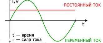
In fact, the voltage in the network is much higher. The socket contains not constant, but alternating voltage of a sinusoidal shape, and the voltmeter measures the effective value of the voltage, which is √2 less than the peak value.
To calculate the power of electrical appliances, it is enough to know exactly the current one, but when determining the parameters of capacitors and insulation, it is necessary to take into account the peak values components Upf = 325V and Upl = 566V.
| Interesting! Linear voltage is related to phase voltage according to the formula Ul = √3Uph. |
What devices can you use to find out phase or zero?
To find the zero or phase, you can also take precise devices that are not very difficult to operate, but will help to accurately determine in which wires the zero or phase is located.
How to determine phase and zero with an indicator screwdriver
The entire internal structure of this device is assembled into a hollow body made of a material with dielectric properties.
The main part of such a screwdriver is a metal pin, which usually has a flat shape.
To reduce the risk of inadvertent contact with other conductive components in the vicinity of the test line, the exposed portion of the tip is usually small.
Important! During the test, the end of the indicator screwdriver should be considered to be in full contact. When the need arises, it is capable of performing the simplest task, for example, unscrewing the screws that secure the cover of a socket or switch
But constant use of it as a screwdriver worsens the quality of the test and negatively affects the overall condition of the device.
The metal rod that fits into the tip of the housing becomes a conductor that is connected to the structure inside the screwdriver. This electrical chip consists primarily of a strong resistor with a minimum value of 500,000 ohms. Its main purpose is to reduce the current intensity when connected to the circuit to a value that is safe for the human body.
The next element is a neon based light bulb, which emits current even at low currents. Mutual electrical contact of all circuit components is ensured by a clamping spring. The screwdriver ends with a plug. It screws into the end of the outer shell (this can be all metal or a metal “heel”). In other words, this element acts as a contact pad during the verification process.
When the contact pad of the screwdriver is touched with a finger, it “joins” the circuit. Firstly, the body itself has electrical conductivity, and secondly, it is a powerful “capacitor”. According to this principle, the process of searching for phase and zero occurs.
In the case when the screwdriver's spike is in phase and the circuit is closed, the voltage is enough to generate a current that does not harm the human body by causing the neon to ignite. In the same situation, if the test falls on the zero contact point, no glow will be emitted.
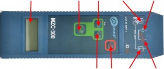
Multimeter
A multimeter is another test and measurement device that a DIYer needs to master. The price of the device is low (the cost of a fully functional model ranges from 300 to 500 rubles*). Moreover, if such a purchase is possible, it is definitely in demand, since the device is multifunctional.
A multimeter should be one of the elements of the tool “arsenal” of a good owner of a house or apartment.
Important! If the wiring consists of three channels: phase conductor, neutral wire and protective earth channel, but without a color code, or if it is unclear, or if its reliability is unknown, the elimination method can be used
Tester
How to determine the phase using a tester:
- The multimeter is getting ready for use. The black test leads are connected to the COM jack and the red test leads are connected to the voltage jack.
- The operating mode switch is placed on the section intended for measuring AC voltage (
V or ACV) and the arrow will be set to a value that is greater than the network value. In another variation it could be, for example, 500, 600 or 750 volts.
Next, the voltage is measured between the stripped conductors. In this case there can be three combinations. The first is that between phase and zero the voltage should be close to the standard voltage of 220 volts. The second is that there can be the same voltage between phase and ground. However, it is true that if the line is equipped with a current leakage protection system (residual current protective device - RCD), this protection can work properly. If there is no RCD or the leakage current is small, the voltage remains within the rated range. Third - there should be no voltage between zero and ground
This is only the last option to show that the wire that does not include the measurement is phase.
Important! After checking, the voltage must be turned off and the bare end of the wire must be insulated and marked. For example, you can stick a white tape and make an appropriate inscription on it