Let’s summarize what has been said by listing the main parameters of the dinistor :
Popular dinistors are unipolar and symmetrical. Reference data.
Dinistor ! A rare animal in our area. His ears are like this, his eyes are like this, and he himself is like this. It’s immediately obvious that the animal came from distant countries. We need to call people, let someone tell us what kind of beast this is.
Wait a second, I'm already here, I'll just rake a little and switch to the open channel. So, let's define what DINISTOR . When Wikipedia is silent, there is no clear formulation that passes from source to source; everyone interprets it in their own way, sometimes not entirely adequately. Let's practice too.
A dinistor is a two-electrode key semiconductor element, the opening of which occurs when a certain voltage is reached between the anode and cathode terminals, depending on the type of the dinistor, and the closure occurs when the current through it decreases to a certain level. We will treat the number of pn junctions built up in the dinistor identically, but the current-voltage characteristics (volt-ampere characteristics), in the best possible way, will help us understand the operation of this type of semiconductor.
Fig.1
Figure 1 (left) shows the current-voltage characteristic of a unipolar (unbalanced) dinistor, which operates only in the presence of a positive bias. If a reverse bias exceeds Urev max, the device may fail.
Symmetrical (bipolar) dinistors work in exactly the same way as unipolar ones, only all of the above is true not only for positive voltages, but also for negative ones. This can be checked by simply changing the polarity of the connected power source.
To visually illustrate the material presented, let's look at the operation of a dinistor sawtooth voltage generator.
Fig.3
This is how the author of the publication “Practical Electronics from the Transistor to the Cybernetic System” R.V. Mayer describes the operation of the above generator.
Let’s summarize what has been said by listing the main parameters of the dinistor :
— Opening (switching on) voltage, Uon; — Minimum holding current, Iud; — Maximum permissible forward current, Ipr; — Leakage current in closed state, Iut; — Maximum permissible reverse voltage, Urev max; — Voltage drop across an open dinistor, Upr; — Rate of voltage rise during switching, dUclose/dt, or Voltage rise time, tr.
the electrical characteristics of the common unipolar dinistors KN102 and symmetrical (bipolar) DB3-D34 dinistors in a final table.
In foreign technical descriptions and diagrams, a dinistor may be called trigger diode, diac (symmetrical dinistor). Indicated on circuit diagrams by the letters VD, VS, V and D.
Among the huge number of various semiconductor devices, there is a dinistor.
In electronic equipment, a dinistor is quite rare; it can be found on printed circuit boards of widely used energy-saving lamps designed for installation in the base of a regular lamp. In them it is used in the starting circuit. In low-power lamps it may not be present.
The dinistor can also be found in electronic ballasts designed for fluorescent lamps.
The dinistor belongs to a fairly large class of thyristors.
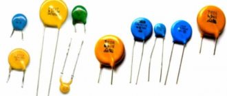
Dinistors
Conventional graphic designation of a dinistor in the diagrams.
First, let’s find out how a dinistor is indicated on circuit diagrams. The conventional graphic designation of a dinistor is similar to the image of a diode, with one exception. The dinistor has another perpendicular feature, which, apparently, symbolizes the base area, which gives the dinistor its properties.
Conventional graphic designation of a dinistor in the diagrams
It is also worth noting the fact that the image of the dinistor on the diagram may be different. So, for example, the image of a symmetrical dinistor in the diagram may be as shown in the figure.
Possible designation of a symmetrical dinistor in the diagram
As we can see, there is not yet any clear standard in the designation of a dinistor in the diagram. Most likely, this is due to the fact that there is a huge class of devices called thyristors. Thyristors include dinistor, thyristor (triac), triac, symmetrical dinistor. In the diagrams, they are all depicted in a similar way as a combination of two diodes and additional lines indicating either the third terminal (trinistor) or the base region (dinistor).
In foreign technical descriptions and diagrams, a dinistor may be called trigger diode, diac (symmetrical dinistor). Indicated on circuit diagrams by the letters VD, VS, V and D.
What is the difference between a dinistor and a semiconductor diode?
Firstly, it is worth noting that the dinistor has three (! ) pn junctions. Recall that a semiconductor diode has only one pn junction. The presence of three pn junctions in a dinistor gives the dinistor a number of special properties.
The principle of operation of the dinistor.
The essence of the dinistor’s operation is that when connected directly, it does not pass current until the voltage at its terminals reaches a certain value. The value of this voltage has a certain value and cannot be changed. This is due to the fact that the dinistor is an uncontrolled thyristor - it does not have a third, control, output.
It is known that a conventional semiconductor diode also has an opening voltage, but it is several hundred millivolts (500 millivolts for silicon and 150 for germanium). When a semiconductor diode is directly connected, it opens when even a small voltage is applied to its terminals.
To understand in detail and clearly the principle of operation of a dinistor, let us turn to its current-voltage characteristic (volt-ampere characteristic). The good thing about the current-voltage characteristic is that it allows you to clearly see how a semiconductor device works.
The figure below shows the current-voltage characteristics of the imported DB3 dinistor. Note that this dinistor is symmetrical and can be soldered into the circuit without observing the pinout. It will work in any case, but the switch-on (breakdown) voltage may differ slightly (up to 3 volts).
Current-voltage characteristic of a symmetrical dinistor
The current-voltage characteristic of the DB3 dinistor clearly shows that it is symmetrical. Both branches of the characteristic, upper and lower, are the same. This indicates that the operation of the DB3 dinistor does not depend on the polarity of the applied voltage.
The graph has three areas, each of which shows the operating mode of the dinistor under certain conditions.
The red section on the graph shows the closed state of the dinistor. No current flows through it. In this case, the voltage applied to the electrodes of the dinistor is less than the switch-on voltage VBO - Breakover voltage.
The blue section shows the moment the dinistor opens after the voltage at its terminals has reached the turn-on voltage (VBO or Uon). At the same time, the dinistor begins to open and current begins to flow through it. Then the process stabilizes and the dinistor goes to the next state.
The green area shows the open state of the dinistor. In this case, the current that flows through the dinistor is limited only by the maximum current Imax, which is indicated in the description for a specific type of dinistor. The voltage drop across an open dinistor is small and fluctuates around 1 - 2 volts.
It turns out that the dinistor in its operation is similar to a conventional semiconductor diode with one exception. If the breakdown voltage or, in other words, the opening voltage for a conventional diode is less than a volt (150 - 500 mV), then in order to open the dinistor it is necessary to apply a switch-on voltage to its terminals, which amounts to tens of volts. So for an imported DB3 dinistor, the typical turn-on voltage (VBO) is 32 volts.
To completely close the dinistor, it is necessary to reduce the current through it to a value less than the holding current. At the same time, the dinistor turns off and goes into the closed state.
If the dinistor is asymmetrical, then when turned on in reverse (“+” to the cathode, and “-” to the anode), it behaves like a diode and does not pass current until the reverse voltage reaches the critical value for this type of dinistor and it burns out. For symmetrical ones, as already mentioned, the polarity of inclusion in the circuit does not matter. It will work anyway.
In amateur radio designs, the dinistor can be used in stroboscopes, high-power load switches, power regulators and many other useful devices.
Thus, in one direction the dinistor behaves like an ordinary diode in reverse connection (simply locked, closed), in the other it opens like an avalanche, but only at a certain voltage across it, or also closes as soon as the current through the open device drops below the specified rating value.
A dinistor is a two-electrode device, a type of thyristor and, as I already said, an incompletely controlled switch that can be turned off only by reducing the current passing through it. It consists of four alternating regions of different conductivity types and has three np junctions. Let's assemble a hypothetical circuit similar to the one we used to study the diode, but add a variable resistor to it, and replace the diode with a dinistor:
So, the resistor resistance is maximum, the device shows “0”. We begin to reduce the resistance of the resistor. The voltage across the dynistor increases, but no current flow is observed. With a further decrease in resistance, at a certain point in time there will be a voltage on the dinistor that is able to open it ( Uopen ). The dinistor immediately opens and the current value will depend only on the resistance of the circuit and the open dinistor itself - the “key” has worked.
How to close the key? We begin to reduce the voltage - the current decreases, but only due to an increase in the resistance of the variable resistor, the state of the dinistor remains the same. At a certain point in time, the current through the dinistor decreases to a certain value, which is usually called the holding current ( Isp ). The dinistor will instantly close, the current will drop to “0” - the key is closed.
Thus, the dinistor opens if the voltage on its electrodes reaches Uopen and closes if the current through it is less than Isp. For each type of dinistor, of course, these values are different, but the operating principle remains the same. What happens if the dinistor is turned on “the other way around”? We assemble another circuit by changing the polarity of the battery.
The resistor resistance is maximum, there is no current. We increase the voltage - there is still no current and there will not be until the voltage on the dinistor exceeds the maximum permissible. As soon as it increases, the dinistor will simply burn out. Let's try to depict what we were talking about on the coordinate plane, on which we plot the voltage across the dynistor along the X axis, and the current through it along the Y axis:
Thus, in one direction the dinistor behaves like an ordinary diode in reverse connection (simply locked, closed), in the other it opens like an avalanche, but only at a certain voltage across it, or also closes as soon as the current through the open device drops below the specified rating value.
Thus, the main parameters of the dinistor can be reduced to several values:
— Opening voltage; — Minimum holding current; — Maximum permissible forward current; — Maximum permissible reverse voltage; — Voltage drop across an open dinistor.
The structure of the dinistor is four-layer with three pn junctions. The emitter junctions of the forward direction are p-n1 and p-n3, the junction p-n2 is the collector junction, of reverse direction, with high resistance. Conclusions:
Dinistor operation diagram
It is easier to understand the operation of a dinistor if you analyze its principle in a diagram of the graphical dependence of current on voltage.
The red line on the graph characterizes the state of the dinistor at a time when it does not conduct current. The voltage here is not enough to open the semiconductor.
The blue line indicates the stage of opening the dinistor at the time when the level U reaches the turn-on level (Uon). It begins to conduct current.
The green line indicates the state of the highest conductivity of the dinistor
"Important! Installing an asymmetrical (unipolar) dinistor without taking into account polarity can lead to its combustion and ultimately increase the voltage!”
A symmetrical dinistor works on the same principle, its only distinguishing feature is the fact that for its operation the condition of maintaining polarity is not mandatory; for this version of dinistors, reverse connection is allowed.
Despite the similarity with the operation of a semiconductor diode, a dinistor has a number of significant differences from it:
- Unlike a diode, which has one pn junction, a dinistor is characterized by the presence of three junctions, which determines its characteristics;
- For a diode, the voltage required to open it is less than a volt (up to 500 mV), but to open a dinistor, a higher voltage is required (for example, for a foreign symmetrical dinistor, a turn-on voltage of 32V is needed).
How is a dinistor graphically indicated in the diagram?
There is no clear standard regulating the depiction of this element on the diagram. The most common option is the image of a diode + an additional perpendicular line. In foreign descriptions, this element can be designated by the words trigger diode, the letters VD, VS, V, D.
The conventional graphic representation of symmetrical dinistors has several options.
The markings applied to the dinistor body consist of letters and numbers. The most popular devices are Russian-made KN102 (A...I). The first letter in the designation characterizes the material from which the device is made. K – silicon. A three-digit number indicates the development number. The letters at the end of the marking are letter codes for the switching voltage.
Similarities between dimmers and lamp protection units
Transistors series kt825, 2t825
I described in detail the lamp protection blocks that smoothly turn on the brightness of the lamps in my articles about the design and connection and diagram of such blocks.
The difference between dimmers and BZ is only in the control method. In protection blocks, the triac is controlled by a controller according to the program. And the program can be anything, up to a wave-like change in brightness. Any analog or digital signal can be controlled. There would be demand.
If you are interested in what I write about, subscribe to receive new articles and join the group on VK!
| Home Radio engineering Checking thyristors, triacs, dinistors |
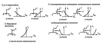
Dynistors, thyristors, triacs are semiconductor devices of a four-layer p-p-p-p structure. Often, when explaining the principle of operation, they are depicted as connected to each other, as shown in Fig. 1, transistors of different conductivity. As can be seen from the figure, the thyristor has three terminals: anode (A), cathode (K) and control electrode (CE). The voltage applied to the p-n junction of one of the transistors ensures that the thyristor is unlocked.
The most common and characteristic malfunction of triacs, thyristors and dinistors is interelectrode breakdown - anode1-anode2, anode-cathode, anode-control electrode, cathode control electrode. For this reason, you should first check the resistance between the electrodes with an ohmmeter. In working triacs, thyristors, dinistors, the A-K (A1-A2) section does not ring. The thyristor and triac, in addition, can be checked for serviceability of the p-n junction between the UE and K, with the exception of devices with a built-in resistor.
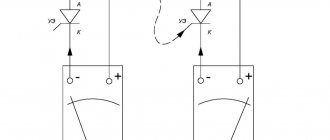
The best results for testing thyristors and triacs are provided by the test circuit shown in Fig. 2. To power the circuit, a 12 V DC source with a permissible load current of at least 200 mA is used. Resistor R1 limits the current through the device under test, and resistor R2 through its control electrode. The circuit provides testing of thyristors and triacs of low and medium power. To check the device you must:
1. Include it in the circuit, as shown in Fig. 2.
2. Briefly connect its UE to resistor R2. The device should open, the voltage +Utest will become close to zero. The device remains open even when the control electrode is disconnected from R2.
3. Break the power supply circuit of the anode (the UE is connected to K) and close it again. The device must be closed. +Utest is equal to 12 V.
When testing triacs, paragraphs should be repeated. 2, 3, and R2 must be powered from the negative pole of the power source.
The result of such testing allows you to verify the serviceability of the device. Nevertheless, the 100% result of testing should be considered to be the correct operation of the semiconductor device in the device where it is installed.
Dinistors (or diacs and seedacs as they are also called) do not have a UE output, and they open when the voltage at the anode exceeds a certain value specified in the parameters for this type of device. As mentioned above, using a multimeter, a dinistor can only be checked for transition breakdown. In order to know for sure whether the dinistor is working or not, it should be checked by including it in a test circuit (Fig. 3), which is powered by an adjustable AC voltage source.
Diode D1 is a half-wave rectifier, capacitor C1 is a smoothing one, resistor R1 limits the current through the dinistor. When checking, you should gradually increase the voltage on the dinistor. When a certain threshold value is reached, it will open, and when the voltage decreases and the flowing current reaches the value of the specified holding current, it will close. After such a check, it is necessary to repeat it, changing the polarity of the voltage applied to the dinistor. When testing, a transformer should be used as the AC voltage source to avoid danger of injury.
Device diagnostics
When checking a radio element for serviceability, a multimeter is most often used. The ease of use of this measuring device is explained by its versatility. With its help, you can test an element for breakdown or measure threshold voltage levels. It does not matter whether the meter is analog or digital.
To obtain correct measurement results, you will need to prepare the multimeter for use. The whole essence of the preparatory operation comes down to checking the tester's battery. When working with a digital device, you must pay attention to the flashing battery icon . If it is, then the battery needs to be replaced. For an analog device, the arrow is set to the zero position before operation. If this cannot be done, then the battery must be replaced.
For a reliable result, when measuring with a multimeter, it is also advisable to monitor the ambient temperature. This is due to the fact that as the temperature increases, the conductivity of semiconductors increases. The optimal temperature for measurement is considered to be around 22 °C.
Continuity without soldering
Due to the specifics of the device, checking the triac with a multimeter without desoldering is not so easy. For a complete check, an electrical circuit is used that allows you to carry out a number of necessary measurements. The only thing that can be done with a multimeter is to check it for obvious breakdown.
To do this, the tester switches to the diode vertebrae mode, after which the measuring probes touch the dinistor terminals. For any polarity, the tester should show a break, which will indicate the absence of a breakdown in the element. But this will not guarantee the serviceability of the device. If during measurement the multimeter shows a short circuit, then such a thyristor can no longer be checked, since it is faulty.
At the same time, you should know that ringing a radio element in the circuit will be incorrect, since other radio elements that affect the measurements can be connected in parallel with its output. When performing a simple test, you need to disconnect at least one of the dinistor inputs from the printed circuit board. In order to check the dinistor without desoldering, you can use the capabilities of the circuit in which it is installed.
It is known that a radio element opens only when a certain voltage level is applied to its terminals, so you can try to reach this threshold value.
In this case, the multimeter switches to voltage measurement mode to check. Depending on the expected breakdown voltage, the measurement range is selected. The measuring probes are connected in parallel to the terminals of the element, after which the signal level is measured. If a voltage surge occurs when the input signal changes, this will indicate the breakdown voltage of the dinistor, that is, its performance.
Test circuit
To gain confidence in the functionality of the element, radio amateurs use test circuits. They come in varying degrees of complexity, which ultimately affects the accuracy of the result obtained. The simplest scheme consists of three elements:
- regulated power supply;
- resistor;
- indicator.
As the latter, you can use an LED. Having assembled such a diagram, we begin to check. A tester is connected parallel to the element in voltage measurement mode.
For example, to check the KU202N thyristor with a multimeter, first set the output voltage level to about twenty volts. In this case, the LED in the circuit should not light up. The level then slowly rises until the LED lights up. The glow of the indicator indicates that the dinistor has opened and electric current has begun to flow through it. To close it, the voltage level is reduced.
The value of the potential difference at which the operating mode changes is the maximum opening voltage. In this case, the tester should show a value of about 50 volts, while the input signal level will be about 60 volts. Any type of resistor can be used. Its purpose is to limit the amount of current passing through the LED.
Knowing how to test the KU 202 thyristor, you can test any other type of thyristor, dinistor or triac. It should be noted that professionals use an oscilloscope instead of a multimeter. A test attachment is used together with it. The elements to be measured are connected to sockets X5 and X6. When using a thyristor, its control element is connected to socket X7. For elements with a control output, the voltage is changed using variable resistor R4. If the radio element is intact, then the oscillogram should be the same as in the figure.
What is a dinistor? The history of its creation
A dinistor is one of the types of thyristors, represented by an uncontrolled trigger diode with two guides. It is characterized by a low electrical breakdown voltage (not higher than 30 V) and the presence of three ph transitions in its four-layer structure.
Although no documented information has been found to date, it is believed that the idea of creating the first dinistor belonged to William Shockley. Based on this idea, in 1955, Frank Gutzwiller in the General Electric laboratory first created this device, which later became widespread and was able to replace thyratrons and other analogues that were relevant at that time.
- Unipolar. Capable of operating exclusively with positive bias. Exceeding the maximum level of reverse voltage will cause the semiconductor to burn out;
- Symmetric. It is a device with equivalent leads, which allows it to operate with both positive and reverse bias.
A schematic representation of dinistors can be presented in different ways; below is one of the options
The dinistor is characterized by the ability to transition from a closed state to an open state. The closed state determines low current conductivity, i.e. In this state, the dinistor practically does not conduct current, with the exception of current leakage. The open state ensures high current conductivity. This transition can be accomplished by exposing the dinistor to a voltage of the required level (turn-on voltage).
The main advantages of the dinistor:
- It provides little power loss;
- Produces a high output voltage level.
The only downside is that the dinistor is an uncontrolled semiconductor, that is, there is no way to control its operation.
The dinistor is capable of operating in the following temperature ranges from -40 to +1250 C.
Purpose of the dinistor
A dinistor is a semiconductor element that has two stable states: closed and open. It is made from a semiconductor single crystal with several pn junctions. In general, it can be considered as an electronic key, when one of its states (closed) corresponds to low conductivity, and the other (open) to high conductivity.
The dinistor belongs to the “thyristor family” of radioelements and has no fundamental differences with the thyristor. The only thing that distinguishes it is the conditions for changing the stable state . Unlike a thyristor, which has three terminals, a dinistor has only two of them, that is, it does not have a control input.
The principle of operation of the dinistor
TRM1 single-channel meter-regulator
Direct connection of the dinistor from the power source leads to a direct bias of the pnp junction P1 and P3. P2 works in the opposite direction, accordingly the state of the dinistor is considered closed, and the voltage drop occurs at the transition P2.
The magnitude of the current is determined by the leakage current and is within the limits of hundredths of microA (section OA). With a gradual increase in voltage, the current will increase slowly; when the voltage reaches a switching value close to the value of the breakdown voltage of the pn junction P2, its current increases sharply, and accordingly the voltage drops.
The position of the device is open, its working component passes into the BV region. The differential resistance of the device in this area has a positive value and lies within small limits from 0.001 Ohm to several units of resistance (Ohm).
To turn off the dinistor, it is necessary to reduce the current value to the holding current value. If reverse voltage is applied to the device, transition P2 opens, transition P1 and P3 are closed.
Rice. No. 2. (a) Structure of the dinistor; (b) CVC
Features of the device of a semiconductor uncontrolled thyristor
The structure of the dinistor is four-layer with three pn junctions. The emitter junctions of the forward direction are p-n1 and p-n3, the junction p-n2 is the collector junction, of reverse direction, with high resistance. Conclusions:
- anode – removed from the p-region;
- cathode – removed from the n-region.
The difference between a dinistor and a diode is the number of pn junctions (a diode has one pn junction), and from a conventional thyristor is the absence of a third, control input.
The main advantages of trigger diode:
- ensuring insignificant power loss;
- possibility of operation in a wide temperature range – -40…+125°C;
- possibility of obtaining high output voltage.
The downside is the inability to control the operation of this device.
Application area
Transistors kt503, 2t503. directory, reference data, parameters, pinout, datasheet, datasheet
The characteristics, low cost and simplicity of the device allow triacs to be successfully used in industry and everyday life. They can be found:
- In the washing machine.
- In the oven.
- In ovens.
- In an electric motor.
- In rotary hammers and drills.
- Dishwasher safe.
- In lighting controllers.
- In a vacuum cleaner.
The list where this semiconductor device is used is not limited to this. The conductor device in question is used in almost all electrical appliances that are in the house. It is entrusted with the function of controlling the rotation of the drive motor in washing machines; they are used on the control board to start the operation of all kinds of devices - it’s easier to say where they are not.
Main characteristics
The semiconductor device in question is designed to control circuits. Regardless of where in the circuit it is used, the following characteristics of triacs are important:
- Maximum voltage. An indicator that, once achieved on the power electrodes, will not cause, in theory, failure. In fact, it is the maximum permissible value, subject to the temperature range. Be careful - even a short-term excess can result in the destruction of this circuit element.
- Maximum short-term pulse current in the open state. The peak value and the period allowed for it, indicated in milliseconds.
- Operating temperature range.
- Unlocking control voltage (corresponds to the minimum constant unlocking current).
- On time.
- The minimum constant control current required to turn on the device.
- Maximum repetitive impulse voltage in the closed state. This parameter is always indicated in the accompanying documentation. Indicates the critical voltage value, the limit for this device.
- The maximum voltage drop across the triac in the open state. Indicates the maximum voltage that can be established between the power electrodes in the open state.
- The critical rate of increase in current in the open state and voltage in the closed state. They are indicated in amperes and volts per second, respectively. Exceeding the recommended values may lead to breakdown or erroneous opening in the wrong place. Operating conditions should be maintained to comply with recommended standards and interference that exceeds the specified dynamics should be eliminated.
- Triac case. Important for thermal calculations and affects power dissipation.
So we looked at what a triac is, what it is responsible for, where it is used and what characteristics it has. The theoretical basics, discussed in simple language, will allow us to lay the foundation for future effective activities. We hope the information provided was useful and interesting for you!
Main characteristics of dinistors
When choosing a suitable dinistor, take into account the following parameters:
- The potential difference in the open state is measured in volts. Indicated in relation to the opening current value.
- The smallest current value in the open state, the unit of measurement is milliamps. This characteristic depends on the temperature of the device. As it increases, the value of the minimum current decreases.
- Switching time is a time period of microseconds during which a trigger diode switches from one stable state to another.
- Locked state current. Depends on the reverse voltage value. In general, its value does not exceed 500 μA.
- Capacity. Measured in picofarads, it characterizes the total parasitic capacitance of the device. If this indicator is high, then the element is not used in high-frequency circuits.
Dimmer repair procedure
Now I will give an example of how to replace a triac with your own hands, using a drill, soldering iron, and an ordinary toothpick.
The triac can be replaced by unscrewing the radiator and removing the triac from the board. But the radiator is now being riveted. The rivet is much more technologically advanced and cheaper in mass production.
Therefore, we pick up a drill with a drill with a diameter of 3.5...5.5 mm.
1 Drill out the radiator rivet
The arrow shows the direction of the drill.
2 Remove the radiator from the triac
The radiator has been removed, now you need to carefully remove the bad triac, causing minimal damage to the board. Recommended soldering iron power is 25 or 40 W.
3 Unsolder the triac from the board. The triac outputs are designated T1, T2, Gate.
Plus, a soldering iron requires experience and dexterity.
Next, we prepare a place for the new triac, using a wooden toothpick for this:
4 Prepare the holes for the new triac
5 Board is ready
6 Place for a new triac
The sites are stuck together, but that doesn’t matter yet. And here are the triac friends, next to the DB3 dinistor:
And here are the triac friends, next to the DB3 dinistor:
7 New triacs and DB3 dinistor
The triacs (BT139, BT138, BT137) in the photo are all for a voltage of 800 Volts, the maximum operating current is 16, 12, and 8 Amps, respectively.
Now we insert a new part into these through holes:
8 Triac is sealed
9 Trimming the legs (conclusions))
The jumper was unsuccessful, it was necessary to use thinner wires...
We carefully check the soldering to ensure there is no short circuit between the contact pads.
Next, we mount the radiator. At home, it is cheaper and more technologically advanced to use a M3 screw, washer and nut.
10 All that remains is to screw on the radiator
Now all that remains is to check the operation in a real connection circuit. Let me remind you that the dimmer is turned on in the same way as a regular switch:
Turning on the light bulb through the brightness control.
For the test circuit, I use a light bulb of any power in the socket, a wire with a plug, and a Vago 222 terminal block.
Advantages and disadvantages
What is the semiconductor device in question needed for? The most popular use case is switching in AC circuits. In this regard, a triac is very convenient - using a small element you can provide control of high-voltage power. Popular solutions are when they replace a conventional electromechanical relay. The advantage of this solution is that there is no physical contact, which makes turning on the power more reliable, switching is silent, the resource is orders of magnitude longer, and the performance is higher. Another advantage of the triac is its relatively low price, which, together with the high reliability of the circuit and time between failures, looks attractive.
The developers were unable to completely avoid the disadvantages. Thus, devices become very hot under load. It is necessary to ensure heat dissipation. Powerful (or “power”) triacs are installed on radiators. Another drawback that affects use is the creation of harmonic interference in the electrical network by some circuits of triac regulators (for example, a household dimmer for adjusting lighting).
Note that the voltage to the load will differ from a sinusoid, which is associated with the minimum voltage and current at which switching on is possible. Because of this, only loads that do not have high power requirements should be connected. When setting the task of achieving a sinusoid, this switching method will not work. Triacs are highly susceptible to noise, transients and interference. High switching frequencies are also not supported.
Thyristor operating modes
Reverse locking mode
Two main factors limit the regime of reverse breakdown and forward breakdown:
In reverse blocking mode, a voltage negative with respect to the cathode is applied to the anode of the device; junctions J1 and J3 are reverse biased, and junction J2 is forward biased (see Fig. 3). In this case, most of the applied voltage drops at one of the junctions J1 or J3 (depending on the degree of doping of the various regions). Let this be transition J1. Depending on the thickness Wn1 of the n1 layer, the breakdown is caused by avalanche multiplication (the thickness of the depletion region during breakdown is less than Wn1) or puncture (the depletion layer spreads over the entire n1 region, and the junctions J1 and J2 are closed).
Direct locking mode
With direct blocking, the voltage at the anode is positive with respect to the cathode and only junction J2 is reverse biased. Junctions J1 and J3 are forward biased. Most of the applied voltage drops at junction J2. Through junctions J1 and J3, minority carriers are injected into the regions adjacent to junction J2, which reduce the resistance of junction J2, increase the current through it and reduce the voltage drop across it. As the forward voltage increases, the current through the thyristor initially increases slowly, which corresponds to the 0-1 section on the current-voltage characteristic. In this mode, the thyristor can be considered locked, since the resistance of junction J2 is still very high. As the voltage across the thyristor increases, the proportion of voltage across J2 decreases and the voltages across J1 and J3 increase faster, causing the current through the thyristor to further increase and increasing the injection of minority carriers into the region of J2. At a certain voltage value (on the order of tens or hundreds of volts), it is called the switching voltage VBF
(point 1 on the current-voltage characteristic), the process acquires an avalanche-like character, the thyristor goes into a state with high conductivity (turns on), and a current is established in it, determined by the source voltage and the resistance of the external circuit.
Two-transistor model
To explain the characteristics of the device in direct blocking mode, we use a two-transistor model. A thyristor can be thought of as connecting a pnp transistor to an npn transistor, with the collector of each connected to the base of the other, as shown in Fig. 4 for triode thyristor. The central junction acts as a collector of holes injected by junction J1 and electrons injected by junction J3. Relationship between emitter currents IE
, collector
IC
and base
IB
and the static current gain α1 of the pnp transistor is also shown in Fig. 4, where ICo is the reverse saturation current of the collector-base junction.
Similar relationships can be obtained for an npn transistor when the direction of the currents is reversed. From Fig. 4 it follows that the collector current of the npn transistor is at the same time the base current of the pnp transistor. Similarly, the collector current of the pnp transistor and the control current Ig
flow into the base of the NPN transistor. As a result, when the total gain in the closed loop exceeds 1, a regenerative process becomes possible.
The base current of the pnp transistor is IB1
= (1 - α1)
IA
-
ICo1
.
This current also flows through the collector of the NPN transistor. The collector current of an npn transistor with gain α2 is IC2
= α2
IK
+
ICo2
.
Equating IB1
and
IC2
, we get (1 - α1)
IA
-
ICo1
= α2
IK
+
ICo2
.
Since IK
=
IA
+
Ig
, then
This equation describes the static characteristics of the device in the voltage range up to breakdown. After a breakdown, the device operates as a pin diode. Note that all terms in the numerator of the right side of the equation are small, therefore, while the term α1 + α2 Direct conduction mode
When the thyristor is in the on state, all three junctions are forward biased. Holes are injected from region p1, and electrons are injected from region n2, and the n1-p2-n2 structure behaves similarly to a saturated transistor with the diode contact removed to region n1. Therefore, the device as a whole is similar to a pin (p + -in + ) diode...
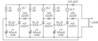
Universal tester for checking DB3, optocouplers, zener diodes and other components
Recently I had to tinker with various electronic ballasts and, in their composition, with a DB3 dinistor, optocouplers and zener diodes from other devices. Therefore, to quickly test these components, a specialized tester had to be developed and manufactured. Additionally, in addition to dinistors and optocouplers, in order not to create more testers for similar components, the tester can test zener diodes, LEDs, diodes, and transistor junctions. It uses light and sound indication and an additional digital voltage meter to assess the level of operation of dinistors and the voltage drop at the junction of the tested zener diodes, diodes, LEDs, and transistors.
! Note: All rights to the diagram and design belong to me, Anatoly Belyaev.
Read also: What does an anemometer measure?
How does it work and what is it for?
A triac is a semiconductor device. Its full name is symmetrical triode thyristor. Its feature is that it is possible to conduct current in both directions. This circuit element has three terminals: one is control, and the other two are power. In this article we will look at the operating principle, structure and purpose of a triac in various circuits of electrical appliances. The table below shows the characteristics of popular triacs:
Table of characteristics of popular triacs.
Design and principle of operation
The peculiarity of the triac is the bidirectional conductivity of the electric current passing through the device. The design of the device is based on the use of two back-to-back thyristors with common control. This principle of operation gave it its name from the abbreviation “symmetrical thyristors”. Since electric current can flow in both directions, it makes no sense to designate the power terminals as anode and cathode. The control electrode completes the overall picture. The triac has five transitions that allow you to organize two structures. Which one will be used depends on the location of formation (specific power terminal) of the negative polarity.
Triac.
Types of dinistors
Depending on the design features, the following types of these devices are distinguished:
- Unipolar. Function only with positive bias. If the maximum permissible reverse voltage level is exceeded, the element will burn out.
- Symmetrical. They have equivalent terminals and can operate with forward and reverse bias. In modern electronics, reversible high-power dinistors (RVD) are widely used. These elements with reversible-impulse properties are capable of switching currents up to 500 kA in the microsecond or submillisecond range. They are used for switching pulse currents in solid-state switches in power supply circuits of power units.
Malfunctions of dimmers on a triac
As a result of short circuit and overload, the triac usually fails. This is the main malfunction; it occurs in 90% of breakdown cases.
The triac is the main element. Its distinctive features are three terminals and a radiator screwed to the body. The most common models are BT137, BT138, BT139.
A faulty triac can be detected with a multimeter. If you test the resistance between terminals A1 and A2 (or T1 and T2, the first and second terminals) in ohmmeter mode, it will be from zero to several ohms. Conclusion - the triac has definitely burned out.
There is another case - the triac rings normally (infinite resistance), but the dimmer, however, does not work (the lamp does not light in all positions of the regulator). Only checking will help here, i.e. inclusion in a real circuit.
Replacing the triac will be discussed in detail below.
In addition to a faulty triac, there are other dimmer faults:
- The power tracks of the printed circuit board burn out. This is a consequence of the main malfunction. The paths will have to be restored with jumpers.
- The mechanical integrity of the regulator (potentiometer or variable resistor) is damaged. From frequent and intensive use, no explanation is needed here.
- In dimmers that have a fuse, you must first check it before repairing. Often the manufacturer provides a spare one, which is stored in the same dimmer as the worker. Rational decision. If it had been in a separate bag, it would have definitely gotten lost.
- Mechanical failure of contacts and soldering of the printed circuit board. First of all, soldering the contacts where the wires are screwed. It also happens that electronic elements are simply poorly soldered by the manufacturer.
- Malfunctions of individual elements. First of all - dinistor, then resistors and capacitors.
Equivalent replacement of lambda diodes
Semiconductor devices such as lambda diodes and tunnel diodes have a very special type of current-voltage characteristics. The current-voltage characteristics of these devices have an N-shaped section.
Lambda diodes and tunnel diodes can be used to generate and amplify electrical signals. In Fig. 8 and fig. Figure 9 shows circuits simulating lambda di-od [RTE 9/87-35].
In practice, generators often use the circuit shown in Fig. 9 [PTE 5/77-96]. If a controlled resistor (potentiometer) or transistor (field-effect or bipolar) is connected between the drains of the field-effect transistors, then the type of current-voltage characteristic of such a “lambda diode” can be controlled within wide limits: adjust the generation frequency, modulate high-frequency oscillations, etc.
Rice. 8. Analog of a lambda diode.
Rice. 9. Analog of a lambda diode.
Causes of dimmer failures
Most often, the cause of failure may be exceeding the maximum permissible load or a short circuit in the load. Excess of load occurs when, for example, lovers of good lighting screw too powerful lamps into chandeliers. Or several lamps are connected through a dimmer, which in total consume too much power.
By the way, when choosing a dimmer, you should select the power with a margin of 30...50%. How to increase the power of a dimmer will be discussed and shown in this article.
A short circuit is possible not only due to faulty wiring. It happens that when light bulbs burn out, a short circuit (short circuit) occurs in them, the nature of which we will not delve into.
In addition, at the moment the incandescent lamp is turned on, a current flows through it, several times higher than the working one. Read more in the article about the resistance of an incandescent lamp.
Thyristor equivalent
Thyristors, dinistors and similar elements are capable of controlling large powers supplied to the load with very minor internal losses.
Thyristors are devices that have two stable states: a low conductivity state (no conductivity, the device is locked) and a high conductivity state (conductivity is close to zero, the device is open). Representatives of the thyristor class:
- diode thyristors (dinistors, diacs), having two terminals (anode and cathode), controlled by applying voltage to the electrodes with a high rate of increase or increasing the applied voltage to a value close to critical;
- triode thyristors (thyristors, triacs), three-electrode elements, the control electrode of which serves to transfer the thyristor from a closed state to an open state;
- tetrode thyristors having two control electrodes;
- symmetrical thyristors - triacs having a five-layer structure. Sometimes this semiconductor device is called a semistor.
Diode thyristors (dinistors), the range of which is not so large, differ mainly in the maximum permissible direct forward voltage in the closed state.
Thus, for dinistors of types KN102A, B, V, G, D, E, ZH, I (2N102A - I), the values of these voltages are, respectively, 5, 7, 10, 14, 20, 30, 40, 50 V with reverse current no more than 0.5 mA. The maximum permissible DC on-state current for these semiconductor devices is 0.2 A with a residual on-state voltage of 1.5 V.
In Fig. Figure 1 shows the equivalent circuit of a low-voltage dinistor. If we take R1 = R3 = 100 Ohm, we can obtain a dinistor with a controlled (using resistor R2) switching voltage from 1 to 25 V [Ya. Voitsekhovsky, R 11/73-40, R 12/76-29]. In the absence of this resistor and under the condition R1 = R3 = 5.1 kOhm, the switching voltage will be 9 B, and with R1 = R3 = 3 kOhm - 12 V.
An analogue of a thyristor with a p-p-p-p structure, described in the book by J. Wojciechowski, is shown in Fig. 2. The letter A indicates the anode; K - cathode; UE - control electrode. In the circuits (Fig. 1, 2) transistors of the KT315 and KT361 types can be used.
It is only necessary that the voltage supplied to the semiconductor device or its analogue does not exceed the maximum rated values. The table (Fig. 2) shows what values of R1 and R2 should be used as a guide when creating an analogue of a thyristor based on germanium or silicon transistors.
Rice. 2. Analogue of a thyristor.
In the breaks in the electrical circuit, shown in the diagram (Fig. 2) with crosses, you can include diodes that allow you to influence the type of current-voltage characteristic of the analogue. Unlike a conventional thyristor, its analogue (Fig. 2) can be controlled using an additional output - the control electrode EDOP, connected to the base of the transistor VT2 (top picture) or VT1 (bottom picture).
Typically, the thyristor is turned on by briefly applying voltage to the control electrode of the UE. When voltage is applied to the electrode, the thyristor, on the contrary, can be switched from the on state to the off state.
Main characteristics of dinistors
When choosing a suitable dinistor, take into account the following parameters:
- The potential difference in the open state is measured in volts. Indicated in relation to the opening current value.
- The smallest current value in the open state, the unit of measurement is milliamps. This characteristic depends on the temperature of the device. As it increases, the value of the minimum current decreases.
- Switching time is a time period of microseconds during which a trigger diode switches from one stable state to another.
- Locked state current. Depends on the reverse voltage value. In general, its value does not exceed 500 μA.
- Capacity. Measured in picofarads, it characterizes the total parasitic capacitance of the device. If this indicator is high, then the element is not used in high-frequency circuits.
How to check DB3 dinistor
The only thing that can be determined with a simple multimeter is a short circuit in the dinistor, in which case it will pass current in both directions. This type of dinistor check is similar to checking a diode with a multimeter.
To fully check the performance of the DB3 dinistor, we must smoothly apply voltage, and then see at what value the breakdown occurs and the conductivity of the semiconductor appears.
Power supply
The first thing we need is an adjustable DC power supply from 0 to 50 volts. The figure above shows a simple diagram of such a source. The voltage regulator indicated in the diagram is a regular dimmer used to adjust room lighting. Such a dimmer, as a rule, has a knob or slider to smoothly change the voltage. Network transformer 220V/24V. Diodes VD1, VD2 and capacitors C1, C2 form a half-wave voltage doubler and filter.
Verification steps
Step 1: Set zero voltage on pins X1 and X3. Connect a DC voltmeter to X2 and X3. Slowly increase the tension. When the voltage on a working dinistor reaches about 30 (according to the datasheet from 28V to 36V), the voltage on R1 will sharply rise to about 10-15 volts. This is due to the fact that the dinistor exhibits negative resistance at the moment of breakdown.
Step 2: Slowly turn the dimmer knob toward decreasing the power supply voltage, and at about 15 to 25 volts, the voltage across resistor R1 should drop sharply to zero.
Step 3: It is necessary to repeat steps 1 and 2, but by connecting the dinistor in reverse.
Principle of operation
Considering a dinistor as a four-structure element, it can be represented in the form of two interconnected transistors of n and p conductivity type. For the transistor to operate, current must appear at the base-emitter junction. If voltage is not applied to it, then no current will pass through the radio element. This is due to the fact that the opening of the transistors is controlled by each other. In other words, in order to open one of these transistors, it is necessary to switch the other one to the open state .
There must be a certain voltage between the terminals of the dinistor, which allows one of the two transistors to switch to saturation mode. As a result, the second element will open and the dinistor will begin to pass current.
To switch the structure to the current cut-off mode, you will need to reduce the voltage, which will lead to the loss of the bias current and, accordingly, the base current on the second transistor. The dinistor will stop passing current.
The polarity of the voltage applied to the terminals of the radio component also plays a significant role. When a minus voltage is applied to the anode, practically no current passes through the element. This kind of inclusion is called inverse. If the polarity is changed, then a small current will begin to flow through the device - the closing current. The voltage corresponding to it determines the highest value at which the dinistor is in the closed state. To open the dinistor, you will need a voltage of the order of tens of volts.
Dynistors, like SCRs, allow current to flow in only one direction . To allow current to flow in both directions, they are connected in an anti-parallel circuit. A five-layer pnpnp type structure can also be used for this.
Checking the dinistor using an oscilloscope
If you have an oscilloscope, then we can assemble a relaxation generator using the tested DB3 dinistor.
In this circuit, the capacitor is charged through a 100k resistor. When the charge voltage reaches the breakdown voltage of the dinistor, the capacitor is sharply discharged through it until the voltage decreases below the holding current at which the dinistor closes. At this moment (at a voltage of about 15 volts), the capacitor will begin to charge again, and the process will repeat.
The period (frequency) from the beginning of the capacitor charge until the breakdown of the dinistor depends on the capacitance of the capacitor itself and the resistance of the resistor. With a constant resistor resistance of 100 kOhm and a supply voltage of 70 volts, the capacitance will be as follows:
- C = 0.015 µF - 0.275 ms.
- C = 0.1 µF - 3 ms.
- C = 0.22 µF - 6 ms.
- C = 0.33 µF - 8.4 ms.
- C = 0.56 µF - 15 ms.
Download datasheet on DB3 (242.6 Kb, downloads: 7,491)
Rotary dimmer on a triac. We will repair it
Therefore, I decided to supplement this information and highlight it in a separate article. Which you are reading now.
As always, there will be many photos with explanations, because it’s better to see once!
An example will be shown of how I repaired the dimmer with my own hands. There will be self-criticism and useful advice.
Checking the dinistor using an oscilloscope
If you have an oscilloscope, then we can assemble a relaxation generator using the tested DB3 dinistor.
In this circuit, the capacitor is charged through a 100k resistor. When the charge voltage reaches the breakdown voltage of the dinistor, the capacitor is sharply discharged through it until the voltage decreases below the holding current at which the dinistor closes. At this moment (at a voltage of about 15 volts), the capacitor will begin to charge again, and the process will repeat.
The period (frequency) from the beginning of the capacitor charge until the breakdown of the dinistor depends on the capacitance of the capacitor itself and the resistance of the resistor. With a constant resistor resistance of 100 kOhm and a supply voltage of 70 volts, the capacitance will be as follows:
- C = 0.015 µF - 0.275 ms.
- C = 0.1 µF - 3 ms.
- C = 0.22 µF - 6 ms.
- C = 0.33 µF - 8.4 ms.
- C = 0.56 µF - 15 ms.
Download datasheet on DB3 (242.6 Kb, downloads: 7,491)
Dinistors are a type of semiconductor devices, more precisely, uncontrolled thyristors. In its structure it contains three p-n junctions and has a four-layer structure.
It can be compared to a mechanical key, that is, the device can switch between two states - open and closed. In the first case, the electrical resistance tends to very low values, in the second, on the contrary, it can reach tens and hundreds of Mohms. The transition between states occurs abruptly.