Insulation resistance, process physics
The most common type of measurement in my practice is measuring insulation resistance. This type of measurement can be made on a cable (before and after high-voltage tests), the stator winding of a turbogenerator, an electric motor, a transformer; even in relay protection, circuits have to be constantly tested. In general, on any electrical equipment that has insulation, it is necessary to monitor its value and identify possible inconsistencies in order to prevent possible adverse consequences for the equipment.
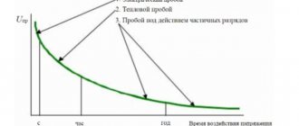
Let's talk about the physical model of insulation resistance. More details about classes and types of insulation will be written in a separate article. Let us clarify that the factors that spoil the insulation are the currents flowing in the equipment and overcurrents (starting, short-circuit currents). In this material I will focus on the insulation equivalent circuit. This will be a circuit consisting of two active resistances and two capacitors. This means that we have:
- C1 - geometric capacity
- C2- absorption capacity
- R1 – insulation resistance
- R2 – resistance, losses in which are caused by absorption currents
Why do you need to know this? Well, I don’t know, maybe to show off in front of people who don’t know these basics. Or, to understand the nature of the passage of direct current through insulation.
The first circuit consists of capacitance C1. This capacity is called geometric; it is characterized by the geometric characteristics of the insulation and its location relative to the ground. This capacitance is discharged instantly when the insulation is grounded after the test. That very same spark when applying grounding to the phase under test after the experiment.
The second circuit contains two elements - capacitance C2 and active resistance R2. This circuit simulates losses when AC voltage is applied to the insulation. R2 characterizes the structure and quality of the insulation. The more frayed the insulation, the lower the R2 value. Capacity C2 is called absorption capacity. This capacitance is charged, when a constant voltage is applied, not instantly, but in a time proportional to the product of R2 by C2. The better the dielectric properties of the insulation, the longer it will take the capacitance C2 to charge, because the value of R2 will be greater for healthy insulation. In general, this capacitance answers the question why, after a spark, it is necessary to keep the grounding on the test core for a couple of minutes. It discharges slowly and does not charge instantly.
The third branch consists of active resistance R3, which characterizes the insulation leakage current and losses. The current increases when the insulation is moistened and is proportional to the insulation area and inversely proportional to the insulation thickness. Here is an electrical model of insulation.
Test characteristics
The main indicator of the insulation condition is its resistance to direct current Riz. The presence of gross external and internal defects (moisture, damage, surface contamination) significantly reduces the insulation resistance. The exact determination of Rout (Ohm) is carried out by a method that allows you to measure the leakage current Iout, which passes through the insulation at the moment a rectified voltage is applied to it:
Riz = Uapp.ext/ Iout
Taking into account the phenomenon of polarization in insulation, determined by the resistance Riz directly depends on the moment of voltage application. The result will be the leakage current measurement at the end of one minute after application, i.e. at the very moment when the absorption current in the electrical insulation mostly dies out.
The next indicator that determines the state of the insulation of transformers and other machines is the absorption coefficient Kabs, which is the ratio of Ris, measured with a megohmmeter one minute after applying a certain voltage, to Ris, which was measured fifteen seconds after the test voltage was applied from megohmmeter:
Kabs = R60/R15
If the electrical insulation is dry, then Kabs is significantly greater than unity; if it is wet, Kabs is close to unity.
This can be explained by the charging time of the absorption capacity of wet and dry insulation. In the case of dry insulation, the time period is long, the charge current changes slowly, Riz, which corresponds to fifteen seconds and one minute after the start of the measurement, are very different.
In the case of wet electrical insulation, the time period is insignificant. Accordingly, the charge current changes quickly and already reaches a steady value by fifteen seconds after the start of measurement. Due to this, Riz, which corresponds to fifteen seconds and one minute after the start of the measurements, are practically the same.
History of the development of the megohmmeter
Let's talk about the history of the development of megaohmmeters. Where did this name come from? Probably due to the name of the measured quantity. By the way, a megohmmeter is also called a meger, or they say to measure the chain. Sound familiar? It turns out, and you probably knew this, the name comes from the name of an ancient measuring equipment company called Megger. This company appeared back in the 19th century, and the first testers were produced back in 1951.
The first megaohmmeters, then still meggers, had handles. You turn the knob, a constant voltage is generated, and you carry out the tests. It was necessary to spin at a frequency of 120 rpm. However, not everyone could spin for a long time. After all, measurements must be made for one minute to determine the absorption coefficient. Therefore, science has stepped forward, and similar megohmmeters have appeared, but with mains power and a voltage supply button. Holding a button is much more convenient than turning a knob. However, there is an inconvenience in the sense that you need to find an outlet.
However, progress did not stop there, and electronic megohmmeters appeared. They are already backlit, it is not necessary to hold the voltage button throughout the test, however, when testing the cable, the residual capacity can burn the device (well, I haven’t checked, but some engineers say so).
Test conditions
The influence of temperature conditions obeys the following law:
Rt2 = Rt1 * 10 ((t2 - t1)/a)
Where: Rt2 and Rt1 are the DC insulation resistance, where T2 and T1 are the temperature. A is a coefficient that depends on the type of electrical insulation; for class B insulation = 60, for class A insulation = 40.
Measurement of the absorption coefficient Kabs and insulation resistance Riz are not carried out if the temperature is less than 10°C, otherwise, due to the unstable behavior of moisture, the measurement results cannot reflect the true state of the insulation. If the temperature is below 0°C, water turns into ice, which is a dielectric.
Measurements are carried out at a relative air humidity of no more than eighty percent in a room at a temperature from 15°C to 35°C, unless other conditions are provided in the technical and standard conditions for wires, cables, equipment and cords.
How to correct megohmmeter, megger, megohmmeter, megameter or something else?)
Attention, I'm telling the truth. I wrote about this in more detail here, but I’ll repeat it again. The correct device for measuring megaohms is called a megohmmeter. Previously, it was called a megohmmeter (for example, in a 1966 book it is called that). New times, new rules. It’s correct to call it a megohmmeter, so let’s use this name in our electrical life. And if megohmmeter is an outdated name, then other interpretations are simply incorrect and illiterate. Although you can, for example, call old devices with a handle, produced in the Soviet Union, megohmmeters, and new digital ones, for example, electronic ones like Sonel, call them megohmmeters. But this is my personal opinion, more of a joke than an opinion.
The main types and brands of megohmmeter devices from my practice (design and principle of operation)
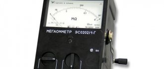
Megaohmmeter ESO-210
Let's start with the simple ones. So, the first participants in today's parade are the Ukrainian devices ESO 210/3 and ESO 210/3G. The letter “G” indicates that the device is powered by an internal generator and has a handle. The model without a handle operates from a 220V network and from a button. They are small in size and easy to use. These are faithful assistants to energy workers. They are convenient for testing any electrical equipment. You can also take one of the ends after the test and ground it with it, because the ends on both sides have metal tips. In models with a handle, an alternating current generator acts as a voltage source, in models with a button - a transformer that converts alternating voltage into direct voltage.
So, let's go through the device settings. The device can be tested by applying a constant voltage of 500, 1000 or 2500 Volts. The readings appear on a dial scale, which has several limits that are switched by a switch. This is a scale of “I”, “II” and “IIx10”.
Scale “I” - lower numbers of the upper scale. The countdown goes from right to left. Values from 0 to 50 MOhm.
Scale “II” - the upper numbers of the upper scale. The countdown goes from left to right. Values from 50 MΩ to 10 GΩ.
Scale “IIx10” - similar to scale “II”, however, values from 500 MOhm to 100 GOhm.
The device also has a lower scale from 0 to 600 V. This scale is available in the ESO-210/3 device and, when the voltage supply button is not pressed, shows the voltage at the ends. In general, we brought the ends of the megohmmeter to the socket, and the needle rose to 220V. But you just need to connect them correctly to measure voltage, not insulation resistance. One on the zipper and the other on the Ux.
When voltage is applied, the red light on the scale lights up, which indicates the presence of voltage at the ends of the device.
How to connect the probes of the device? We have three holes for connecting probes - a screen, a high voltage and a third measuring hole (rx, u). In general, two probes are paired and one of them is signed. It is not easy for an attentive person to make a mistake.
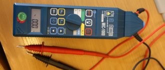
Megaohmmeter sonel mic-2510
Let's step further and focus our attention on a powerful Polish device called Sonel - megohmmeter mic-2510. This megohmmeter is digital. Outwardly, it is very nice, the kit includes a bag in which alligator type probes (quite powerful and reliable) and plug-in ones are folded. In addition, the kit includes a charger. The device itself runs on a battery, which is quite convenient. No network connection is required and no rotation of the knob is required, as with older models of domestic megohmmeters. There is also a tape for comfortable placement on the neck. At first it didn’t seem very convenient to me, but eventually you get used to it and realize all the advantages. In addition to a reliable battery, the advantages include the ability to supply voltage without holding the button. To do this, first press start, then “enter” and that’s it – watch the readings and don’t let anyone get under voltage.
This device can measure the following quantities using a two-wire and three-wire method. The three-wire method is used for measurements where it is necessary to exclude the influence of surface currents - transformers, cables with a screen.
The device can also measure temperature using temperature sensors, voltage up to 600 volts, and low-resistance contact resistance.
The device scale has values of 100, 250, 500, 1000, 2500 Volts. This is a wide enough range to suit engineers' needs for a wide range of testing needs. From absorption coefficient to polarization coefficient. The maximum measurable insulation resistance that the device can measure is 2000 GOhm - an impressive value.
The polarization coefficient characterizes the degree of aging of the insulation. The smaller it is, the more worn the insulation is. The polarization coefficient is 2500V and we measure the insulation resistance after 60 and 600s or after 1 and 10 minutes. If it is more than two, then everything is fine, if from 1 to 2, then the insulation is questionable, but if the polarization coefficient is less than 1, it’s time to sound the alarm. Western chief engineers do not welcome high-voltage tests, by the same AID, but are happy to conduct a vigilante test at 5 kV or 2.5 kV with the measurement of this coefficient.
The absorption coefficient is the ratio of the insulation resistance after 60 and 15 seconds. This coefficient characterizes the moisture content of the insulation. If it tends to unity, then it is necessary to raise the issue of drying the insulation. More details about its value for different types of equipment are described in the electrical equipment testing standards of your country.
In the process of work, I came across other devices, but these two show how far progress has come in the production of megaohmmeters. Each of the devices I have seen has its pros and cons.
How to use a megohmmeter
How are insulation resistance measurements made (the most popular measurement, which is performed with a megaohmmeter) for various electrical equipment. Let's consider how to test using the example of the power system of the Republic of Belarus. Although, the norms are basically the same, with minimal differences.
Measuring insulation resistance with a megohmmeter, continuity testing using a megohmmeter
Before starting the measurement, it is necessary to check that the device is working; for this it is necessary to apply voltage with the ends shorted and closed. When closed we should get “0”, and when open we should have infinity (since we measure the air insulation resistance). Next, we place one end on the ground (grounding bolt, busbar, grounded equipment case), and the other on the tested phase, winding. Two people carry out the tests, one holds the ends, and the second supplies the voltage. The reading is recorded after 15 seconds and after 60. At the end, the conductor to which the voltage was applied is grounded and after a minute or two (depending on the magnitude and time of voltage application), the ends are removed and measurements are made on another conductor according to a similar circuit.
How can you test anything using a megohmmeter? Testing is a test for circuit integrity. A dial is the first device an electrician has to assemble himself from a light bulb, battery and wires. How to ring using a megohmmeter? The megohmmeter does not quite ring, it shows that there is no connection between the phase and the ground, that is, the absence of a winding short circuit to the ground. However, if you apply high voltage, it is quite possible to burn the relay or motor winding.
Measuring the insulation resistance of electric motors with a megohmmeter
This means that we come to an electric motor, for example this is a 380-volt motor of some kind of pump. Remove the cover and disconnect the power cable. Next we apply 500V and see. If at the end of the minute the resistance is less than 1 MOhm, it means it does not meet the standards. The absorption coefficient is not standardized for small electric motors. Voltage is supplied between one phase and ground. The other two phases are connected to the housing. At the end of the test, the tested conductor is grounded.
Measuring cable insulation resistance with a megohmmeter
So we have a cable. On the one hand, it is, for example, connected to a starter, and on the other hand to an electric motor or drive that starts the electric motor. We need to flash this cable. We disconnect it from the starter and from the electric motor. We place a person at the electric motor if it is in another room, so that no one is allowed near the open wires that we will test. Next, we apply a voltage between the core and ground of 2500 V for a minute. The insulation resistance value for cables with voltages up to 1000V must be at least 0.5 MOhm. For cables with voltages above 1 kV, the insulation resistance value is not standardized. If the megohmmeter shows zero, it means that the core is broken and you need to look for the location of the damage and the distance to the defect. The insulation resistance between the cores is also measured. Or they combine three conductors to the ground and if the value is inadequate, then it is necessary to measure each conductor to the ground separately.
Also, at the end of the tests, it is necessary to hang the grounding wire on it before removing the wire through which the voltage was supplied. The more voltage is applied, the longer you need to wait. For high-voltage cables this time reaches several minutes.
Procedure for checking cable insulation resistance with a megohmmeter
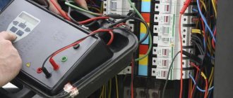
You come to the site and see, for example, the following picture.
Before directly checking the insulation resistance, you must make sure that:
- The cable cores are ringed and marked (read about ringing here)
- on the cable cores where we will supply voltage there is no dirt, scale, or paint (there is no such thing on the cable core, but it may be on the grounding, which is painted, or it may be covered with a layer of rust, then you need to scrape it off with a screwdriver or knife)
- at the other end of the cable no one is working and the cable is disconnected from the load and the power source (it is not worth applying voltage to the installer, who can cut the cable from the other side, or measuring the Rx of the cable with the load, it is also worth making sure that we do not apply high voltage to the secondary circuits and elements that can become unusable at 2500V, so sometimes they are simply switched to 500V)
- the cable is de-energized and measures are in place to prevent accidental supply of voltage to the cable under test (locks, posters, cells removed)
- if the vigilante test (measurement of insulation resistance) is combined with high-voltage tests, then you need to make sure that there is a person at the second end of the cable (the second end is opposite from the test site) or the room is locked and fenced with posters posted
- The megohmmeter is in good condition and suitable for use (verification mark on the body and the ends of the device are tested)
- you have the right and qualifications to work with a megohmmeter and perform this type of work (group 3 on electrical safety and an unexpired test of special knowledge, plus a medical examination)
- the megohmmeter wires must have high insulation (here you can also do the following: connect the two megohmmeter wires and apply voltage - the value should be zero, since there is no insulation between the wires, and if you separate them, then infinity - since the air resistance is high)
Once the above points have clearly been implemented, you can get down to business. Let's play together!
Safety when working with a megohmmeter
Since the megohmmeter supplies high voltage, it is a potential source of danger both for those who supply this voltage and for those who are near the equipment or cable to which this voltage is supplied.
What do you need to remember when working with a megohmmeter? Firstly, it is necessary to correctly connect the ends to the device, and secondly, it is necessary to securely fasten the ends through which voltage is supplied to the electrical equipment. Also, do not forget about grounding the equipment under test, both before and after the measurement, to remove any residual charge.
What and where will we experience?
Such objects requiring measurements may be the following:
- residential buildings and premises (cottages, apartments, penthouses, country houses);
- administrative buildings and premises (offices, business centers, etc.);
- stations of cellular operators;
- industrial enterprises;
- entertainment complexes (clubs, cinemas, gyms, game rooms);
- gas and petrol stations;
- retail premises and complexes (super and hypermarkets, shops, shopping pavilions), etc.
In short, any object where electrical equipment is located, with the exception of equipment whose operating voltage is less than 60 V.
The result of the measurements are certain indicators, the value of which influences the decision on the suitability of electrical insulation or its replacement.
Tricks with a megaohmmeter
About tricks with a megaohmmeter, I can only note that we have one employee whom we tested at 500 volts, here, as he says, the main thing is to keep the ends tight and not let go. Attention!!! I don’t advise you to repeat this!!! . It was a terrible sight, of course. But theoretically, the current is small and the thermal effect is not annoying.
In general, I wish you good luck in your work with a megohmmeter, and be careful, because our profession is not only very interesting, but also quite dangerous. TB above all!!!
Read more about measuring Rx cable with a megohmmeter
You can also familiarize yourself with a multimeter