Using the right hand rule in electrodynamics
If you hang a frame with current in a magnetic field on a thin and flexible wire, it will rotate and be positioned in a certain way. The behavior of a magnetic needle is similar. This indicates the vector nature of the physical quantity characterizing the magnetic field. In this case, the direction of this vector will be related to the orientation of the frame and arrow. The physical vector quantity that characterizes the magnetic field is the magnetic induction vector ($\vec{B}$).
Finished works on a similar topic
Coursework The rule of the left and right hand for a magnetic field 480 ₽ Abstract The rule of the left and right hand for a magnetic field 270 ₽ Test work The rule of the left and right hand for a magnetic field 220 ₽ Get completed work or advice from a specialist on your educational project Find out the cost
This is one of the main parameters that describe the state of the magnetic field, so you need to be able to find its magnitude and, of course, direction.
To determine the direction of the magnetic induction vector, use:
- right screw rule or
- right hand rule.
The direction of the magnetic induction vector, at the location of the frame with current, is considered to be the direction of the positive perpendicular ($\vec{n}$) to this frame. The positive normal ($\vec{n}$) will have the same direction as the direction of translational movement of the right screw if its head is rotated along the current in the frame (Fig. 1 (a)).
Figure 1. Determination of the direction of the magnetic induction vector. Author24 - online exchange of student work
Thus, having a test frame with current, placing it in the field under study, allowing it to rotate freely in it, you can determine the direction of the magnetic induction vector at each point in the field. You just need to let the frame come to a balanced position, then use the right screw rule.
Have questions about this topic? Ask a question to the teacher and get an answer in 15 minutes! Ask a Question
Now let's look at the right hand rule. Let's clench our right hand into a loose fist (Fig. 2). Bend your thumb 90°. Let's place the hand so that the thumb indicates the direction of current flow, then the bent other four fingers will indicate the direction of the lines of magnetic induction of the field that creates the current. And we remember that the tangent at each point of the field to the field line (magnetic induction line) indicates the direction $\vec{B}$.
Figure 2. Right hand rule. Author24 - online exchange of student work
Let's consider a solenoid. Let's clasp it with our right palm so that four fingers coincide with the direction of the current in it, then the finger bent ninety degrees will indicate the direction of the magnetic field created inside it.
We know that if a conductor is moved in a magnetic field, an induction current will arise in this conductor. The right hand rule can be used to determine the direction of flow of induced current in such conductors. Wherein:
- the magnetic field induction lines should enter the open palm of the right hand,
- bend the finger of this hand ninety degrees and direct it according to the speed of movement of the conductor,
- the extended four fingers will indicate the direction of the induction current.
The right-hand rule can be used to determine the direction of the induced emf in a circuit:
With the bent four fingers of your right hand, grasp the contour in which the EMF is induced when the magnetic flux changes, bend the thumb of this hand ninety degrees and direct it in the direction of the magnetic flux when it increases (or against the direction of the magnetic flux when it decreases), then the bent fingers will point in the direction opposite to the EMF.
Cards-tasks “Rules of the gimlet and the left hand” 9th grade
| Option 1 | |||
| 1. Draw the magnetic field lines around a current-carrying conductor. Determine the direction of the magnetic field induction vector at point A. | 2. Draw the magnetic field lines around the current-carrying frame. Determine the direction of the magnetic field induction vector at point A. | ||
| 3. Determine the location of the poles of permanent magnets | 4. Determine the direction of the current in the conductor | 5. Determine the direction of the force acting from a uniform magnetic field on the frame section ab | |
2. Draw the magnetic field lines around the current-carrying frame. Determine the direction of the magnetic field induction vector at point A.
3. Determine the direction of the current in the conductor
4. Determine the direction of the force acting on a current-carrying conductor from the magnetic field
5. Determine the direction of the force acting from a uniform magnetic field on the frame section bd
2. Draw the magnetic field lines around the current-carrying frame. Determine the direction of the magnetic field induction vector at point A.
3. Determine the direction of the force acting on a current-carrying conductor from the magnetic field
4. Determine the direction of the current in the conductor
5. Determine the direction of the force acting from a uniform magnetic field on the frame section cd
2. Draw the magnetic field lines around the current-carrying frame. Determine the direction of the magnetic field induction vector at point A.
3. Determine the location of the poles of permanent magnets
4. Determine the direction of the force acting on a current-carrying conductor from the magnetic field
5. Determine the direction of the force acting from a uniform magnetic field on the frame section ab
2. Draw the magnetic field lines around the current-carrying frame. Determine the direction of the magnetic field induction vector at point A.
3. Determine the direction of the current in the conductor
4. Determine the direction of the force acting on a current-carrying conductor from the magnetic field
5. Determine the direction of the force acting from a uniform magnetic field on the frame section bd
2. Draw the magnetic field lines around the current-carrying frame. Determine the direction of the magnetic field induction vector at point A.
3. Determine the location of the poles of permanent magnets
4. Determine the direction of the force acting on a current-carrying conductor from the magnetic field
5. Determine the direction of the force acting from a uniform magnetic field on the frame section cd
| Option 7 | |||
| 1. Draw the magnetic field lines around a current-carrying conductor. Determine the direction of the magnetic field induction vector at point A. | 2. Draw the magnetic field lines around the current-carrying frame. Determine the direction of the magnetic field induction vector at point A. | ||
| 3. Determine the direction of the current in the conductor | 4. Determine the direction of the force acting on a current-carrying conductor from the magnetic field | 5. Determine the direction of the force acting from a uniform magnetic field on the frame section ab | |
2. Draw the magnetic field lines around the current-carrying frame. Determine the direction of the magnetic field induction vector at point A.
3. Determine the direction of the force acting on a current-carrying conductor from the magnetic field
4. Determine the direction of the current in the conductor
5. Determine the direction of the force acting from a uniform magnetic field on the frame section bd
| Option 9 | |||
| 1. Draw the magnetic field lines around a current-carrying conductor. Determine the direction of the magnetic field induction vector at point A. | 2. Draw the magnetic field lines around the current-carrying frame. Determine the direction of the magnetic field induction vector at point A. | ||
| 3. Determine the location of the poles of permanent magnets | 4. Determine the direction of the force acting on a current-carrying conductor from the magnetic field | 5. Determine the direction of the force acting from a uniform magnetic field on the frame section cd | |
2. Draw the magnetic field lines around the current-carrying frame. Determine the direction of the magnetic field induction vector at point A.
3. Determine the location of the poles of permanent magnets
4. Determine the direction of the force acting on a current-carrying conductor from the magnetic field
5. Determine the direction of the force acting from a uniform magnetic field on the frame section ab
2. Draw the magnetic field lines around the current-carrying frame. Determine the direction of the magnetic field induction vector at point A.
3. Determine the location of the poles of permanent magnets
4. Determine the direction of the current in the conductor
5. Determine the direction of the force acting from a uniform magnetic field on the frame section bd
2. Draw the magnetic field lines around the current-carrying frame. Determine the direction of the magnetic field induction vector at point A.
3. Determine the location of the poles of permanent magnets
4. Determine the direction of the force acting on a current-carrying conductor from the magnetic field
5. Determine the direction of the force acting from a uniform magnetic field on the frame section cd
2. Draw the magnetic field lines around the current-carrying frame. Determine the direction of the magnetic field induction vector at point A.
3. Determine the direction of the current in the conductor
4. Determine the direction of the force acting on a current-carrying conductor from the magnetic field
5. Determine the direction of the force acting from a uniform magnetic field on the frame section ab
2. Draw the magnetic field lines around the current-carrying frame. Determine the direction of the magnetic field induction vector at point A.
3. Determine the direction of the current in the conductor
4. Determine the direction of the force acting on a current-carrying conductor from the magnetic field
5. Determine the direction of the force acting from a uniform magnetic field on the frame section bd
| Option 15 | |||
| 1. Draw the magnetic field lines around a current-carrying conductor. Determine the direction of the magnetic field induction vector at point A. | 2. Draw the magnetic field lines around the current-carrying frame. Determine the direction of the magnetic field induction vector at point A. | ||
| 3. Determine the direction of the force acting on a current-carrying conductor from the magnetic field | 4. Determine the direction of the force acting on a current-carrying conductor from the magnetic field | 5. Determine the direction of the force acting from a uniform magnetic field on the frame section cd | |
2. Draw the magnetic field lines around the current-carrying frame. Determine the direction of the magnetic field induction vector at point A.
3. Determine the location of the poles of permanent magnets
4. Determine the direction of the force acting on a current-carrying conductor from the magnetic field
5. Determine the direction of the force acting from a uniform magnetic field on the frame section ab
Option
17
1. Draw the magnetic field lines around the current-carrying conductor. Determine the direction of the magnetic field induction vector at point A.
2. Draw the magnetic field lines around the current-carrying frame. Determine the direction of the magnetic field induction vector at point A.
3. Determine the location of the poles of permanent magnets
4. Determine the direction of the current in the conductor
5. Determine the direction of the force acting from a uniform magnetic field on the frame section bd
2. Draw the magnetic field lines around the current-carrying frame. Determine the direction of the magnetic field induction vector at point A.
3. Determine the direction of the current in the conductor
4. Determine the direction of the force acting on a current-carrying conductor from the magnetic field
5. Determine the direction of the force acting from a uniform magnetic field on the frame section cd
2. Draw the magnetic field lines around the current-carrying frame. Determine the direction of the magnetic field induction vector at point A.
3. Determine the direction of the current in the conductor
4. Determine the direction of the force acting on a current-carrying conductor from the magnetic field
5. Determine the direction of the force acting from a uniform magnetic field on the frame section ab
2. Draw the magnetic field lines around the current-carrying frame. Determine the direction of the magnetic field induction vector at point A.
3. Determine the direction of the force acting on a current-carrying conductor from the magnetic field
4. Determine the direction of the current in the conductor
5. Determine the direction of the force acting from a uniform magnetic field on the frame section bd
| Option 21 | |||
| 1. Draw the magnetic field lines around a current-carrying conductor. Determine the direction of the magnetic field induction vector at point A. | 2. Draw the magnetic field lines around the current-carrying frame. Determine the direction of the magnetic field induction vector at point A. | ||
| 3. Determine the direction of the current in the conductor | 4. Determine the direction of the force acting on a current-carrying conductor from the magnetic field | 5. Determine the direction of the force acting from a uniform magnetic field on the frame section cd | |
2. Draw the magnetic field lines around the current-carrying frame. Determine the direction of the magnetic field induction vector at point A.
3. Determine the direction of the force acting on a current-carrying conductor from the magnetic field
4. Determine the direction of the current in the conductor
5. Determine the direction of the force acting from a uniform magnetic field on the frame section ab
| Option 23 | |||
| 1. Draw the magnetic field lines around a current-carrying conductor. Determine the direction of the magnetic field induction vector at point A. | 2. Draw the magnetic field lines around the current-carrying frame. Determine the direction of the magnetic field induction vector at point A. | ||
| 3. Determine the location of the poles of permanent magnets | 4. Determine the direction of the force acting on a current-carrying conductor from the magnetic field | 5. Determine the direction of the force acting from a uniform magnetic field on the frame section bd | |
2. Draw the magnetic field lines around the current-carrying frame. Determine the direction of the magnetic field induction vector at point A.
3. Determine the location of the poles of permanent magnets
4. Determine the direction of the force acting on a current-carrying conductor from the magnetic field
5. Determine the direction of the force acting from a uniform magnetic field on the frame section cd
| Option 25 | |||
| 1. Draw the magnetic field lines around a current-carrying conductor. Determine the direction of the magnetic field induction vector at point A. | 2. Draw the magnetic field lines around the current-carrying frame. Determine the direction of the magnetic field induction vector at point A. | ||
| 3. Determine the location of the poles of permanent magnets | 4. Determine the direction of the current in the conductor | 5. Determine the direction of the force acting from a uniform magnetic field on the frame section ab | |
2. Draw the magnetic field lines around the current-carrying frame. Determine the direction of the magnetic field induction vector at point A.
3. Determine the location of the poles of permanent magnets
4. Determine the direction of the force acting on a current-carrying conductor from the magnetic field
5. Determine the direction of the force acting from a uniform magnetic field on the frame section bd
| Option 26 | |||
| 1. Draw the magnetic field lines around a current-carrying conductor. Determine the direction of the magnetic field induction vector at point A. | 2. Draw the magnetic field lines around the current-carrying frame. Determine the direction of the magnetic field induction vector at point A. | ||
| 3. Determine the direction of the current in the conductor | 4. Determine the direction of the force acting on a current-carrying conductor from the magnetic field | 5. Determine the direction of the force acting from a uniform magnetic field on the frame section cd | |
2. Draw the magnetic field lines around the current-carrying frame. Determine the direction of the magnetic field induction vector at point A.
3. Determine the direction of the current in the conductor
4. Determine the direction of the force acting on a current-carrying conductor from the magnetic field
5. Determine the direction of the force acting from a uniform magnetic field on the frame section ab
| Option 29 | |||
| 1. Draw the magnetic field lines around a current-carrying conductor. Determine the direction of the magnetic field induction vector at point A. | 2. Draw the magnetic field lines around the current-carrying frame. Determine the direction of the magnetic field induction vector at point A. | ||
| 3. Determine the direction of the force acting on a current-carrying conductor from the magnetic field | 4. Determine the direction of the force acting on a current-carrying conductor from the magnetic field | 5. Determine the direction of the force acting from a uniform magnetic field on the frame section bd | |
2. Draw the magnetic field lines around the current-carrying frame. Determine the direction of the magnetic field induction vector at point A.
3. Determine the location of the poles of permanent magnets
4. Determine the direction of the force acting on a current-carrying conductor from the magnetic field
5. Determine the direction of the force acting from a uniform magnetic field on the frame section cd
Explanation of the name
Most people remember mention of this from a physics course, namely the electrodynamics section. This happened for a reason, because this mnemonic is often given to students to simplify their understanding of the material. In fact, the gimlet rule is used both in electricity, to determine the direction of the magnetic field, and in other sections, for example, to determine angular velocity.
A gimlet is a tool for drilling small-diameter holes in soft materials; for a modern person, it would be more common to use a corkscrew as an example.
Important! It is assumed that the gimlet, screw or corkscrew has a right-hand thread, that is, the direction of its rotation when tightened is clockwise, i.e. right
The video below provides the full formulation of the gimlet rule, be sure to watch it to understand the whole point:
Product vector
Gimlet can help with the next question - determining the vector product. In this case, this rule is interpreted as follows:
- Two vectors have a common starting point, but a different direction.
- The 1st vector factor must be rotated along the shortest path until it is in relation to the 2nd vector factor.
- During this rotation, the screw will rotate towards the vector product.
This rule also takes into account the right-handed orientation of the gimlet thread. This rule also applies to clockwise direction. If you rotate the vector factor clockwise until it and the second vector factor are aligned, then the direction of movement will depend on who is rotating this vector. The rotation will also be carried out inside the plane (clock).
To visualize, you need to spread the thumb, middle and index fingers on your right hand. When this rule is applied in electrodynamics, the following can be obtained:
When all three fingers are displaced, we obtain clockwise movement, as well as the sum of the products of all vectors.
Solenoid Features
The electromagnetic field is created by a coil connected to a power source. Using the example of a ring structure, the uneven distribution of power lines is clear. This makes it difficult to create working schemes with given design parameters.
The noted disadvantage is eliminated using a solenoid. With a sufficiently large number of turns, a uniform field with parallel lines of force is formed in the central part. “Edge” distortions, if the length is significantly greater than the diameter, can be neglected. In fact, this design performs the functions of a permanent magnet. A significant advantage is the ability to create products with calculated (changeable) operating parameters.
Coil and ring design
To clarify the field parameters, take a coil, as shown in the picture. The clenched fingers are guided taking into account the connected power supply. Provides coincidence with current. The thumb is bent to the side. It will show the direction in which the vector of magnetic induction lines is directed.
For your information. The gimlet rule is applied in a similar way. Using this method, a screw is screwed in from the “+” of the connected battery to the “negative” terminal.
Right hand
The right-hand rule is used to mnemonicly determine the direction of movement of electromagnetic induction. The formulation of this algorithm is as follows: you need to clench your palm into a fist and raise your thumb up. In this gesture, the finger imitates an electrical conductor and the direction of movement of electric current. And 4 clenched fingers indicate the direction of the magnetic induction lines.
In physics, the gimlet is considered to be the standard. For easier understanding, this tool can be represented as a screw, a screw with a right-hand thread, or a drill.
The gimlet rule is not a definitive definition. It can be interpreted very differently when it is necessary to determine angular velocity, magnetic induction, mechanical rotation and angular momentum.
Rule of nines for determining burn area
In order to determine the area of affected tissue during burns, the “rule of nines” is used. Its essence lies in the fact that the area of skin on each individual part of the body has its own percentage ratio to the total area of tissue of the whole body:
- head and neck – 9%;
- hands – 9% each;
- breast – 9%;
- belly – 9%;
- back – 9%;
- lower back and buttocks – 9%;
- hips – 9% each;
- lower leg and foot – 9% on each leg;
- groin area – 1%.
This is how the burn area in adults is determined. In order to understand the extent of a burn in children under five years of age, the “rule of fives” is usually used. It works on exactly the same principle, only each designated area of the body accounts for 5%.
Solenoid
The right-hand rule also allows you to determine which direction the magnetic field is in solenoids and inductors. Coils also consist of wire, but the difference is that this wire is wound into a spiral, which means it does not have a direct direction. Also, in the presence of a magnetic core that interacts with current, the value of the magnetic field strength increases significantly. In order to determine the direction of the magnetic field lines in the solenoid, it is necessary:
- The wire in the coil has the value "I" and is a conductor of electric current.
- Current flows through the coil from a higher potential to a lower one, and therefore from “+” to “−”. In this case, the coil is vector "B".
- We take the coil with our right hand and extend our thumb along the element itself.
This rule is interpreted as follows: the coil has a magnetic induction vector “B”, the direction of which coincides with the direction of the thumb. The 4 fingers holding the coil indicate the direction of flow of electric current. This rule is also based on the right-hand twisting of the gimlet. This orientation can be used when performing various experiments when calculations are not required and using left-handed orientation, which is taken into account in advance.
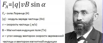
What is the Lorentz force - definition, when it occurs, obtaining the formula
It is known that electric current is the ordered movement of charged particles. It has also been established that while moving in a magnetic field, each of these particles is subject to the action of a force. For a force to occur, the particle must be in motion.
The Lorentz force is a force that acts on an electrically charged particle as it moves in a magnetic field. Its direction is orthogonal to the plane in which the vectors of particle velocity and magnetic field strength lie. The resultant of the Lorentz forces is the Ampere force. Knowing it, we can derive a formula for the Lorentz force.
The time required for a particle to pass a segment of a conductor, , where is the length of the segment and is the speed of the particle. The total charge transferred during this time through the cross section of the conductor is . Substituting here the time value from the previous equality, we have
(2)
At the same time, where is the number of particles located in the conductor under consideration. In this case, where is the charge of one particle. Substituting the value from (2) into the formula, you can get:
Thus,
Using (1), the previous expression can be written as
After reductions and translations, a formula appears for calculating the Lorentz force
Taking into account the fact that the formula is written for the force modulus, it must be written as follows:
(3)
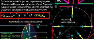
Since , then to calculate the modulus of the Lorentz force, it does not matter where the velocity is directed - in the direction of the current or against it - and we can say that - this is the angle formed by the vectors of the particle velocity and magnetic induction. Writing the formula in vector form will look like this:
Writing the formula in vector form will look like this:
is a vector product, the result of which is a vector with a modulus equal to .
Based on formula (3), we can conclude that the Lorentz force is maximum in the case of perpendicular directions of the electric current and magnetic field, that is, when , and disappears when they are parallel ().
It must be remembered that to obtain the correct quantitative answer - for example, when solving problems - you should use SI units, in which magnetic induction is measured in teslas (1 T = 1 kg s−2 A−1), force in newtons (1 N = 1 kg m/s2), current strength - in amperes, charge in coulombs (1 C = 1 A s), length - in meters, speed - in m/s.
Right hand rule. Lorentz force.
Introductory Notes
The right-hand rule is usually used by schoolchildren to determine where a charged particle moving in a magnetic field .
The force that deflects such particles is called the Lorentz force
The magnitude of the Lorentz force is calculated in school using the formula
F = q ⋅ v ⨯ B
B
— vector of magnetic induction
v—particle speed
q is the particle charge
⨯ is the cross product.
After multiplying charge by velocity and induction we get the Lorentz force. Its value can be calculated on a calculator simply by multiplying the remaining values by each other.
Any force is a vector, therefore, a force has not only a magnitude, but also a direction.
The direction of any vector product can be easily found by knowing the directions of the factors.
This is why you need the right hand rule .
And as you might have guessed, it can be applied not only to the Lorentz force, but also to any other vector products.
Required knowledge
Before you get acquainted with the right-hand rule, you need to understand how the direction of electric current is determined.
Electrons and negatively charged ions move from the cathode to the anode. Protons, holes and positively charged ions move in the opposite direction - from the anode to the cathode.
The direction of electric current is taken to be the direction opposite to that in which the electrons are moving.
The right-hand rule is denoted as follows: The direction in which a particle will deviate from its original trajectory under the influence of a magnetic field depends on the charge of the particle.
Electrodynamics and magnetostatics
Magnetic induction is a vector factor that characterizes a force field. The value shows the influence of the magnetic background on negatively and positively charged particles in the space under study. Induction determines the strength of the field's influence on a charge moving at a given speed. For this case, the application laws are described as follows:
- Screw rule. If the forward circular motion of the gimlet coincides with the direction of the charged electrons in the coil, then the path of rotation of the tool handle will coincide with the course of the magnetic vector of polar induction, the direction depending on the current.
- Right hand principle. If you take the rod in your right hand so that the finger set at a right angle shows the course of the current, then the other fingers will correspond to the direction of the magnetic induction beam produced by the current. The path of the magnetic induction vector is laid tangent to the line of segments.
For a moving conductor
A metal rod contains a large number of free electrons, the movement of which is characterized as chaotic. If the coil moves in an electromagnetic force field along the lines, then the background deflects electrons moving simultaneously with the conductor. Their movement creates EMF (electromotive force) and is called electromagnetic induced induction.
Current will flow under the influence of a potential difference when such a coil is connected to an external circuit in a closed circuit. When the rod moves in the direction of the field lines, the effect of the field on the charges is reduced to zero. There is no electromotive force, no voltage, no electron current.
You may be interested in: Causes and consequences of a short circuit
The induced emf is equal to the product of the working size of the conductor, the speed of the rod and the value of magnetic induction. Its direction is established according to the law of the right hand. The palm is positioned so that the lines of the force field are directed into it, and the thumb bent at 90° is placed along the movement of the rod. In this position, four straightened fingers will show the course of the induction current.
General concept
You can find out the path of the perpendicular to two selected vectors and understand the direction of the rod using several methods. In physics, the gimlet rule determines the force vector of the electromagnetic field at the initial point and the direction of the turns of the conductor around the rotational center.
The methods of applying the rule interact with each other in the case of determining a positive course when calculating the product of the elements of vector distance and coordinate system. The basis is a compatible set of rays. Moreover, each element in the region is a single linear combination of segments.
Conclusions:
- in magnetic space, a stationary magnet, a moving body, and particles with different charges interact;
- the behavior of electrons depends on the action of the electromagnetic field;
- the moving conductor is a guide for the movement of charged elements, and the lines of force act on the magnetoelectric conductor.
The principle determines the guiding indicators of the body that moves in the magnetic field. Choosing the path of a vector quantity is a conditional concept, but it always goes the same way. The polarity is constant.
Application of the rule
There are several ways to diagnose the course of a vector and coordinate values perpendicular to the original rays. Sometimes you need to characterize only one of these concepts. The algorithm is used to calculate the direction of the main formats instead of other methods. In this case, the position of the factors in the matching formulas must be known.
When applying the wording of the gimlet rule, the conductor is taken in the hand, and 4 fingers are folded into a fist. The main finger remains in a vertical position - up or down. It shows the course of the electrical flow. Fingers placed parallel coordinate the direction of the electromagnetic potential field lines.
An extended thumb can allow the wire rod to move evenly and send an electric current. When using the right-hand rule, the wire to be tested is placed in the palm of your hand. The clenched four fingers indicate the direction of the magnetic lines extending into the palm.
The right hand rule is applied when determining the tendency of electric current in a solenoid. The inductive coil is taken in the appropriate hand so that the closed fingers indicate the direction of the current in the windings. The thumb positioned at 90º shows the path of potential lines inside the device. The direction of the electric current is determined with known polarity indicators.
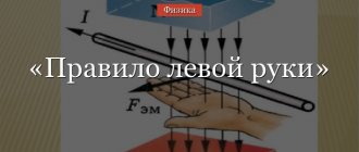
When using the left-hand rule, the conductor is positioned so that the vector induction indicators are directed to the center of the palm, and straightened fingers indicate the course of current flow. The thumb shows the direction of the Ampere force interacting with the magnetic field rod.
In the second version of the left-hand rule, the conductor is placed in the hand so that the potential lines follow the plane of the palm at right angles, and the fingers show the movement of positive particles. This direction should be opposite to the movement of negative particles. The thumb will show the course of the Lorentz force.
Mechanical rotation
The rotational vector depends on the angular velocity beam and the start of motion at the starting point. The value is calculated by multiplying vectors. Radial speed shows the rate at which an object rotates around its axial center.
The radial speed value is shown:
- numerical value when rotating in a two-dimensional area;
- a conditional vector when moving in a three-dimensional area: the coordinates of the ray change direction and sign when the coordinate system changes;
- a quantity that changes sign with a change in indexation in the general arrangement.
Sometimes multiplying vectors is enough, but in other cases simple and convenient methods are needed. The pattern of the screw and the right palm is used when finding the course of the beam module.
Methods for finding the path of a segment module:
- the law states that turning the gimlet in the direction of rotation of the wire shows the path of angular velocity;
- according to the law of the right palm, the wire is taken with the corresponding hand and rotated along the course of four fingers, while the main finger shown indicates the direction of the angular velocity.
The direction of the impulse torque changes in direct proportion to the speed of the axial rotations. The positive momentum coefficient is used to calculate the value.
Potential moment and magnetism
The turning and twisting moment is a physical quantity. It is congruent to the product of radial rays and potential drawn from the central line to the point of application. The characteristics of the moment determine the pressure indicators on the solid body.
The rules are almost the same as defining a module path, but differ in some elements:
- the gimlet rule says that a revolution of the screw along the path of potential rotation of the body will show the course of the moment of force;
- according to the right-hand rule, the conductor rotates in the hand in the direction of the extended fingers (along the path of application of the rotation potential), and the direction of the main finger at an angle of 90º will indicate the course of the turning moment.
In science, induction is a vector combination that characterizes magnetic space. The value shows the effect of the electromagnetic field on polarized electrons. Induced induction expresses the force of the field on a particle moving at a selected speed.
Example of applying the rule:
- if the uniform rotation of the gimlet corresponds to the course of the current in the solenoid, then the direction of the handle coincides with the sending of the magnetic induction beam;
- the right hand is placed so that the main finger indicates the direction of movement of the electrons, and the bent fingers indicate the path of the beam of the resulting induction.
The metal rod contains free charges that move chaotically. The movement of a conductor in electromagnetic space leads to the deflection of polarized particles and the creation of a targeted induction of electromagnetic space.
Electrons accumulate at one end of the axial rod, and there is a shortage of particles at the other. Lenz's rule says that the induced current of the circuit goes in the direction that weakens the causes of the electron current. When the wire moves along the course of the lines of force, the effect of the area on the charges decreases, and there is no electromotive potential.
A little history
The first attempts to describe electromagnetic force were made back in the 18th century. Scientists Henry Cavendish and Tobias Mayer proposed that the force on magnetic poles and electrically charged objects obeys the inverse square law. However, the experimental proof of this fact was not complete and convincing. It was only in 1784 that Charles Augustine de Coulomb, using his torsion balance, was able to finally prove this assumption.
In 1820, the physicist Oersted discovered the fact that a volt current acts on the magnetic needle of a compass, and Andre-Marie Ampere in the same year was able to develop a formula for the angular dependence between two current elements. In fact, these discoveries became the foundation of the modern concept of electric and magnetic fields. The concept itself was further developed in the theories of Michael Faraday, especially in his idea of lines of force. Lord Kelvin and James Maxwell added detailed mathematical descriptions to Faraday's theories. In particular, Maxwell created the so-called “Maxwell field equation” - which is a system of differential and integral equations that describe the electromagnetic field and its relationship with electric charges and currents in vacuum and continuous media.
JJ Thompson was the first physicist to try to derive from Maxwell's field equation the electromagnetic force that acts on a moving charged object. In 1881, he published his formula F = q/2 vx B. But due to some miscalculations and an incomplete description of the bias current, it turned out to be not entirely correct.
And finally, in 1895, the Dutch scientist Hendrik Lorentz derived the correct formula, which is still used today, and also bears his name, just as the force that acts on a flying particle in a magnetic field is now called the “Lorentz force.”
Hendrik Lorenz.
First task
The first task is drawing. Place a sheet of paper and a pencil (felt-tip pen) in front of your child and invite him to draw what he wants. Don't rush your child. After he finishes the drawing, ask him to draw the same thing with his other hand. Children often refuse: “I don’t know how,” “I can’t do it.” You can reassure your child: “I know that it is difficult to draw the same picture with your right (left) hand, but try.” Encourage him, tell him that he is doing everything right. In this task you need to compare the quality of the drawings. Make sure that the child holds a pen or pencil correctly and comfortably, does not strain while completing the task, and sits correctly. In all the tasks given below, the dominant hand should be considered the one that performs the more active action.
Answer
Take a sharpened pencil. Imagine that a current can flow through a pencil and it flows from the blunt end to the tip. Grasp it with your RIGHT hand so that the bent thumb points towards the point. In which direction do the other fingers turn to grasp? This is the DIRECTION of the MAGNETIC field line of a given current.
So, the RIGHT hand is the grasper.
Now straighten your LEFT HAND, connecting four fingers, and bending the thumb perpendicular to the other four fingers. Now our pencil will play the role of a vector of the EXTERNAL magnetic field. Let this vector enter the palm of your LEFT hand, perpendicular to it. (You poke your palm with the point of a pencil) In this case, the palm (its plane) will have a very definite orientation in space. Imagine that you pierced your palm and it (the palm) can spin on the pencil like a piece of kebab on a skewer. ROTATE your palm so that the FOUR folded fingers show the DIRECTION of the current. A bent finger will show the direction of AMPERE FORCE or LORENTZ FORCE (The direction of current is the movement of POSITIVE charges, a whole bunch of charges is Ampere, and a single charge is Lorentz)
LEFT arm is paralyzed. IT CANNOT BE BENDED.
Let's summarize. The right grip determines the magnetic field of the current, the Left paralysis determines the direction of the force from the external magician. fields for current or MOVING charge.
Superposition principle – Common field – VECTOR sum of all fields. You can only add HOMOGENEOUS quantities. You CANNOT add an electric field to a magnetic one, or a gravitational field to an electric one.
I hope I explained it clearly, but the fact that it’s a little with a “bloody” slant, so when you poke yourself in the palm with the tip, you’ll immediately remember the rule)))
Rule for angular velocity
The principle of the right-hand rule can be applied if you need to determine the angular velocity of a rotating object. First you need to consider:
- Velocity vector "v".
- Angular velocity vector "ω".
- A vector that is drawn from a fixed point to a given “r”.
All these parameters are interconnected by a vector product. The formula we use for this product will be as follows:
The formulation of angular velocity when using the gimlet rule sounds like this. If you rotate the gimlet in the direction in which the body is rotating, then the direction of screwing will show the direction of the angular velocity of this body. In the case of right rotation of the gimlet, the angular velocity will be directed to the right and vice versa.
Using the right hand rule, this formulation is interpreted more simply: if you hold a rotating body in your right hand, then the thumb will indicate the direction vector of the angular velocity, and the other 4 fingers will point to the direction of rotation.
What not to do
- Do not tear off stuck-on clothing if it does not come off after soaking. In this case, it is better to wait for the arrival of doctors who can do this under sterile conditions.
- Do not apply iodine or brilliant green to the burn - these products are too aggressive and dry out already irritated skin. In addition, it will be more difficult for the doctor to determine the extent of the damage if the entire burn site is green or brown.
- Do not treat the skin directly after a burn with fatty products, oils, creams, or sour cream. The oily environment increases the local body temperature, and a film forms on the surface of the skin, which prevents the burn from cooling naturally.
- Do not burst blisters after a burn with boiling water yourself.
- If you doubt whether to apply a bandage and how to do it, it is better not to do it. A bandage that is too tight can cause swelling.
A 1st degree burn does not require any action and will heal in a couple of days. You can speed up recovery by taking care of your skin, moisturizing and nourishing it.
Immediately after first aid, you can apply a medicated bandage to the skin. There are special napkins for sale after burns with an analgesic effect - use them or make a bandage yourself by soaking the gauze or bandage with anti-burn agent. Use La Cree cream to soothe irritated skin. It contains panthenol, so the cream is perfect for treating burns with boiling water.
A 2nd and 3rd degree burn with minor damage still requires contacting a medical facility. It is necessary to carry out some procedures to disinfect the burn surface, which are performed by a doctor.
The skin at the burn site is anesthetized, treated with an antiseptic, exfoliated epidermis, dirt and remnants of clothing are removed, the doctor carefully pierces the blisters after the burn, removing the liquid and leaving a thin skin to protect the wound. A bandage with bactericidal ointment is applied to the burn. Further treatment is carried out independently or under the supervision of a doctor, if it is necessary to replace the bandage every 2-3 days until the burn is completely healed.
Serious 3rd and 4th degree burns and burns of more than 30% of the body are treated exclusively in a hospital. The first actions of doctors are aimed at removing dead tissue. If necessary, this is done surgically. The patient is under the supervision of doctors, they eliminate the consequences of burn shock, which causes intoxication of the body and damage to internal organs.
After the damaged skin is sloughed off, a scab begins to form
At this stage, it is important to prevent the development of inflammation. Depending on the location of the burn and the degree of skin damage, treatment is carried out in an open or closed manner; the affected areas of the body are lubricated with an antiseptic ointment 3-4 times a day.
Examples of problems in physics and electrical engineering
Example 1
Simple physics problems to determine the direction of the Ampere force using the left-hand rule.
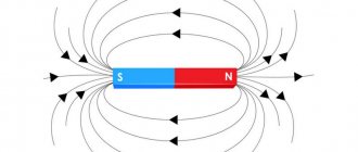
Task
Given a magnet: north on the left, south on the right. Where is the Ampere force directed?
Solution
- the current is always directed from south to north (from the positive to the negative end);
- Let's imagine that we take this magnet in our left hand;
- We place four fingers (except the thumb) in the direction of the current (from right to left, from south to north);
- the position of the thumb placed at a right angle will show us that the Ampere force is directed downward. We note:
On topic: What exercises can you do to pump up your arms?
Example 2
Now north is on the right and south on the left.
Solution: focusing on the previous problem, we can immediately conclude that here the Ampere force will be directed upward. Or check it again by placing your right hand according to the left hand rule. We mark the direction:
More complex tasks.
Example 3
Task
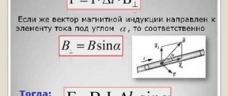
Determine the force with which a uniform magnetic field acts on a conductor 20 cm long if the current strength in it is 300 mA, located at an angle of 45º to the magnetic induction vector. Magnetic induction is 0.5 Tesla.
Solution
\(F_A=B\times J\times L\sin\left(\alpha\right)\)
Example 4
Task
Determine the force exerted on a charge of 0.005 C moving in a magnetic field with an induction of 0.3 T at a speed of 200 m/s at an angle of 45º to the magnetic induction vector.
Solution
Works of any complexity
Qualified help from experienced authors
Source
Physics test Left hand rule 9th grade
Physics test Left hand rule. Detection of a magnetic field by its effect on an electric current for 9th grade students with answers. The test includes 10 multiple-choice questions.
1. The direction of current in magnetism coincides with the direction of movement
1) electrons 2) negative ions 3) positive particles 4) none of the answers is correct
2. The square frame is located in a uniform magnetic field as shown in the figure. The direction of the current in the frame is indicated by arrows.
The force acting on the bottom side of the frame is directed
3. An electric circuit consisting of four straight horizontal conductors (1-2, 2-3, 3-4, 4-1) and a direct current source is in a uniform magnetic field, the lines of force of which are directed vertically upward (see Fig., view above).
The force acting on conductor 4-1 is directed
1) horizontally to the right 2) horizontally to the left 3) vertically up 4) vertically down
4. An electrical circuit consisting of four straight horizontal conductors (1-2, 2-3, 3-4, 4-1) and a direct current source is in a uniform magnetic field, the lines of which are directed horizontally to the right (see figure, top view ).
The force acting on conductor 1-2 is directed
5. The operation of an electric motor is based on
1) the effect of a magnetic field on a conductor with electric current 2) electrostatic interaction of charges 3) the phenomenon of self-induction 4) the effect of an electric field on an electric charge
6. The main purpose of the electric motor is to convert
1) mechanical energy into electrical energy 2) electrical energy into mechanical energy 3) internal energy into mechanical energy 4) mechanical energy into various types of energy
7. The magnetic field acts with a non-zero force on
1) atom at rest 2) ion at rest 3) ion moving along magnetic induction lines 4) ion moving perpendicular to magnetic induction lines
8. Select the correct statement(s).
A. to determine the direction of the force acting on a positively charged particle, four fingers of the left hand should be placed in the direction of the particle’s speed B. to determine the direction of the force acting on a negatively charged particle, four fingers of the left hand should be placed against the direction of the particle’s speed
1) only A 2) only B 3) both A and B 4) neither A nor B
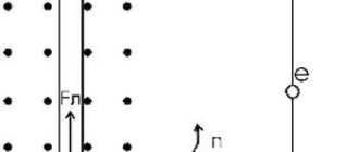
9. A positively charged particle with a horizontally directed velocity v flies into the field region perpendicular to the magnetic lines. Where is the force acting on the particle directed?
1) Vertically down 2) Vertically up 3) On us 4) From us
10. A negatively charged particle with a horizontally directed velocity v flies into the field region perpendicular to the magnetic lines. Where is the force acting on the particle directed?
1) Towards us 2) From us 3) Horizontally to the left in the drawing plane 4) Horizontally to the right in the drawing plane
Answers to a physics test Left-hand rule Detection of a magnetic field by its effect on an electric current 1-3 2-4 3-2 4-3 5-1 6-2 7-4 8-3 9-4 10-2
PDF version Test Left-hand rule Detection of a magnetic field by its effect on an electric current (137 Kb, pdf)
Mnemonic rules for individual cases
Magnetic induction lines
The presented technologies are not required for use in solving practical problems. The right hand rule in physics is used as an auxiliary tool. Calculations are made using standard vector algebra techniques. However, quite often an accelerated clarification of the direction of magnetic lines or another parameter is required. Information about current strength in amperes and other precise data are not always needed. In situations like these, the gimlet rules of physics come in handy.
For angular velocity
To consider mechanical systems, it is often necessary to operate with expressions for angular velocity (w) and displacement (v). The direction of the vector w is determined by the movement of the gimlet.
For angular momentum
The same principle is used to clarify the parameters of angular momentum (L), which depends on the total mass and its distribution in the object under study. However, you can find out the direction of the vector using a simple gimlet rule.
For a moment of strength
According to the classical definition, torque (M) is equal to the product of force vectors (F) and radius (r), which connects the points of the axis of rotation and the places of application of the corresponding impact. For calculations, complex calculations are used using integrals and angular projections. The movement of the body will correspond to the movement of the gimlet. This implies rotation of its handle in the direction of the corresponding moment of force.
Magnetostatics and electrodynamics
The Earth creates a powerful field that protects people from solar radiation. Under its influence, the compass needle moves to a certain position. The current passing through the conductor creates a force to rotate the motor. The reverse algorithm of actions is used to generate electricity. The noted processes can be formulated and described by a set of equations. The right-hand rule allows you to determine individual parameters in electrodynamics without unnecessary complications.
Magnetic induction
The phenomenon in question was discovered at the beginning of the 19th century. The main dependencies of physical quantities are determined by Faraday’s law:
E = – dФ/dt,
Where:
- E – electromotive force;
- Ф – magnetic flux, which is created by the induction vector;
- t – control time interval.
Later, the dependence of EMF not only on the form of the external force was determined. Current also appears in a conductor that moves in a stable magnetic field. Bio-Savard established the vector dependence experimentally. Later, Laplace made a general definition and clarified the principles of calculations for a moving unit charge. These postulates became the basis of modern magnetostatics.
In the above expression, the “minus” in front of the second part is explained by the condition that the lines of the corresponding magnetic flux (Lorentz’s law) are oppositely directed to the current in the conductor.
For a simplified consideration of the methodology, the gimlet rule will be briefly denoted further in the text by the abbreviation “PB”. The rule of the left hand or the right is “PLR” or “RPR”, respectively. Other abbreviations to indicate directions:
- movement of the screw (gimlet) - NDB;
- rotating the handle - NVR;
- thumb set at a right angle - NBP;
- folded other fingers - NSP.
Conditional abbreviations
| Method | Correspondence |
| PB | |
| NDB | current in the control conductor |
| NVR | vector (V) created by the passed current |
| PPR | |
| NBP | current |
| NSP | power lines |
For current in a conductor moving in a magnetic field
| Determination method | Correspondence |
| PPR | |
| NBP | control wire movement |
| NSP (straight palm, lines of force enter perpendicularly) | induced current |
Maxwell's equations
In this case, the possibility of expressing the rotor operation through the product of two vectors is used. For ease of understanding, we can imagine a rotating liquid medium having a certain angular velocity.
Methods for determining basic parameters
| Method | Correspondence |
| PB | |
| NDB | rotor vector expression |
| NVR | field turbulence |
| PPR | |
| NBP | rotor vector (flux that passes through the control circuit) |
| NSP | vortices (induced electromotive force) |
Problems on the topic “Lorentz force”
Even if you are not a beginner, before solving problems, read the general instructions and keep useful formulas on hand just in case.
Lorentz force problem No. 1
Condition
An electron with an energy of 300 eV moves perpendicular to the induction lines of a uniform magnetic field with a strength of 465 A/m. Determine the Lorentz force, speed and radius of the electron trajectory.
Solution
The electron speed can be found from the kinetic energy formula:
Eк=m·v22v=2Eкm
The Lorentz force is a centripetal force, which means that according to Newton’s second law, we can write:
Magnetic induction is equal to the intensity multiplied by the magnetic constant. Substituting the previously found expression for speed into the formula for radius and Lorentz force, we write:
R=m2EctqμH=2EctqμHFl=q2EctμH
Now all that remains is to substitute the values and calculate:
v=2 4.8 10-169.1 10-31=3.25 107 msFl=4 3.14 10-7 465 1.6 10-19 3.25 107 =3·10-15НR=2·4.8·10-16·9.1·10-314·3.14·10-7·465·1.6·10-19=.32 m
Answer: v=3.25·107 ms; Fl=3·10-15N; R=.32 m.
Lorentz force problem No. 2
Condition
An alpha particle flies into a magnetic field with an induction of 1 Tesla perpendicular to the field lines. Find the angular momentum of the particle relative to the center of the circle along which it will move.
Solution
When a particle flies into the field perpendicular to the lines of force, the Lorentz force begins to act on it, which acts as a centripetal force. The radius of the circle along which the particle will move:
R=mvQBm=6.65·10-27 kg – mass of the alpha particleQ=2e=3.2·10-19 C – charge of the alpha particle
We find the angular momentum of the particle relative to the center of the circle using the formula:
L=mvR=m2v2QB=6.65 10-272 .35 10723.2 10-19 1=5.42 10-21 kg m2s
Answer: 5.42·10-21 kg·m2s.
Lorentz force problem No. 3
Condition
In a uniform magnetic field with induction B = 0.5 T, a rod of length l = 20 cm rotates with a frequency n = 10 s-1. The axis of rotation is parallel to the induction lines and passes through one of the ends of the rod perpendicular to its axis. Determine the potential difference U at the ends of the rod.
Solution
Let us consider the physical essence of the processes taking place in the rod. When a rod moves in a magnetic field, an induced emf arises in it, which is caused by the action of the Lorentz force on the charges of the rod.
Under the influence of this force, a separation of charges occurs in the rod: free electrons move upward and a potential difference arises between the ends of the rod.
The charges at the ends of the rod create a field E, which prevents further separation of charges. At some point, the Lorentz force will be balanced with the force of the emerging field:
Fl=e·EE=Fle=evBe=vB
The speed of the lower end of the rod, and therefore the speed of the electrons in it, can be found by knowing the rotation frequency and the length of the rod:
v=2π·n·l
Taking this into account, the expressions for the electric field strength will be rewritten:
E=2πnlB
The induced potential difference, by definition, is equal to:
U=E lU=2πnl2B=2 3.14 10-1 .22 .5=1.3V
Answer: 1.3 V.
Lorentz force problem No. 4
Condition
What force acts on a charge of 0.005 C moving in a magnetic field with an induction of 0.5 T at a speed of 150 m/s at an angle of 45 degrees to the magnetic induction vector?
Solution
This is the simplest problem to determine the Lorentz force. Let us recall the formula and write that the Lorentz force acts on the charge, equal to:
F=q·v·B·sinα
Let's substitute the values and calculate:
F=.005·150·.5·22=.26 N
Answer: 0.26 N.
Lorentz force problem No. 5
Condition
A body with a charge of 0.8 mC moving in a magnetic field is acted upon by a force equal to 32 N. What is the speed of the body if the magnetic field vector is perpendicular to it?
Solution
This is a classic problem using the Lorentz force formula. Since the velocity and magnetic induction vectors are perpendicular, we can write:
F=qvBsinα=qvBv=FqB=32.8·10-3·2=20·103 ms
Answer: 20000 m/s.
Are you undergoing magnetostatics? You may also be interested in:
- Problems on the Biot-Savart-Laplace law.
- Problems on the magnetic field circulation theorem.
Application of Lorentz force in technology
Kinescope
The kinescope, which was installed until recently, when it was replaced by an LCD (flat) screen, in every TV, would not have been able to work without the Lorentz force. To form a television raster from a narrow stream of electrons on the television screen, deflection coils are used, in which a linearly varying magnetic field is created. Line coils move the electron beam from left to right and return it back; frame coils are responsible for vertical movement, moving the beam running horizontally from top to bottom. The same principle is used in oscilloscopes - devices used to study alternating electrical voltage.
Watch this video on YouTube
Mass spectrograph
A mass spectrograph is a device that uses the dependence of the radius of rotation of a charged particle on its specific charge. The principle of its operation is as follows:
A source of charged particles that gain speed using an artificially created electric field is placed in a vacuum chamber in order to eliminate the influence of air molecules. The particles fly out from the source and, having passed along a circular arc, hit the photographic plate, leaving marks on it. Depending on the specific charge, the radius of the trajectory and, therefore, the point of impact changes. This radius is easy to measure, and knowing it, you can calculate the mass of the particle. Using a mass spectrograph, for example, the composition of lunar soil was studied.
Cyclotron
The independence of the period, and therefore the frequency of rotation of a charged particle from its speed in the presence of a magnetic field, is used in a device called a cyclotron and designed to accelerate particles to high speeds. A cyclotron is two hollow metal half-cylinders - dees (each of them resembles the Latin letter D in shape), placed with straight sides facing each other at a short distance.
The dees are placed in a constant uniform magnetic field, and an alternating electric field is created between them, the frequency of which is equal to the frequency of rotation of the particle, determined by the magnetic field strength and specific charge. Falling under the influence of an electric field twice during the rotation period (when moving from one dee to another), the particle accelerates each time, increasing the radius of the trajectory, and at a certain moment, having gained the required speed, flies out of the device through the hole. In this way, a proton can be accelerated to an energy of 20 MeV (megaelectronvolt).
Magnetron
A device called a magnetron, which is installed in every microwave oven, is another representative of devices that use the Lorentz force. The magnetron is used to create a powerful microwave field, which heats the internal volume of the oven where the food is placed. The magnets included in its composition correct the trajectory of electrons inside the device.
Earth's magnetic field
And in nature, the Lorentz force plays an extremely important role for humanity. Its presence allows the Earth's magnetic field to protect people from the deadly ionizing radiation of space. The field prevents charged particles from bombarding the surface of the planet, causing them to change direction.
Coulomb's law, definition and formula - electric point charges and their interaction
Determining the direction of the magnetic induction vector using the gimlet rule and the right hand rule
What is induced emf and when does it occur?
History of the discovery of electricity
How to convert amps to watts and vice versa?
How to connect a single-phase electric motor - circuit with a capacitor
Lorentz force direction
The direction of the Lorentz force is indicated by a brown arrow. The force itself is designated as F
. The trajectory of negatively charged particles is indicated in blue, provided that:
- The negatively charged particle initially flew from left to right
- The magnetic field induction vector is directed from the screen
The red color indicates the trajectory of a positively charged particle under the same conditions.
A straight black line indicates the movement of a particle that has no charge. The magnetic field does not act on it and it moves as it moved from left to right.
How is the magnetic field related to the Gimlet and hands?
Considering the movement of fields of current and magnetic nature, one can easily trace the mutual connection of the Buravchik rule with the canons of the right and left hands. For a better comparison of these concepts, we should consider what they represent separately.
Gimlet's law precisely establishes the direction of tension caused by magnetic fields. In this case, the field itself must be placed in the direct direction relative to the conductive material with electric current.
For a more complete picture, take a corkscrew with a right-hand thread and screw it in clockwise in the direction of current flow. The direction of the magnetic fields corresponds to the right-hand movement of the corkscrew handle.
The right hand rule can be considered in two versions. In one of them, fingers bent into a fist cover a stationary conductor. They indicate in which direction the vector of magnetic lines is facing, which, like that of the Gimlet handle, will be clockwise. The largest finger extends 90º and shows in which direction the current is moving.
If the conductor moves, then the right hand is placed in a different way. The palm is placed between the north and south poles so that it is perpendicular to the lines of force passing through it. The large finger is fixed in a vertical position and points in the direction of the directional movement of the conductor. The remaining fingers, extended forward, look in the same direction as the induction current. This installation has found its application in calculations of coil solenoids that affect the physical properties of the current.
By separating the right and left hand rules from each other, their physics shows that the second option used in the calculations works differently. The left palm is placed in such a position that four fingers are directed towards the current moving along the conductor. Magnetic lines, moving from one pole to another, enter the palm at 90 degrees. The protruding large finger points in the same direction as the force acting on the conductor.
Definition
The author of the gimlet rule is theoretical physicist Pyotr Sigismundovich Buravchik. With its help, the direction of the axial vector with a known basis vector was determined. This rule is used in the case of mnemonic definition using the right and left hands.
This rule is a mnemonic algorithm for establishing electromagnetic induction, based on the established direction of movement of the electric current, which is the exciter of magnetic fields.
This rule can be explained more briefly and clearly as follows:
- The gimlet is pointed downward and screwed in clockwise.
- Its tip imitates the direction vector of electric current.
- At the moment of screwing, the orientation of the magnetic induction lines coincides with the direction of movement of the gimlet handle.
The generally accepted rule is that the direction of movement of the coil is to the right. Accepting this fact, we can conclude: when the current moves along the shortest path in one direction, namely from a positive value to a negative value, the magnetic induction lines will be directed to the right. The condition is relevant for a direct conductor.
The gimlet rule has two main varieties:
- Right hand rule.
- Left hand rule.
Next, an explanation and a concrete example will be given for easier understanding.