The electricity everyone needs is transmitted through wires suspended from poles of various designs and power lines. For safety, the distance between power line supports and their height are of great importance. GOST regulates all sizes based on the current strength in the wires, material and design of the support. The location of power transmission line supports in open areas or in populated areas is also of great importance.
In the village
Distance between transmission line towers: 10 kV, 110 kV and 35 kV transmission line poles
The electricity everyone needs is transmitted through wires suspended from poles of various designs and power lines. For safety, the distance between power line supports and their height are of great importance. GOST regulates all sizes based on the current strength in the wires, material and design of the support. The location of power transmission line supports in open areas or in populated areas is also of great importance.
Factors on which the distance between pillars depends
In different places, the distance between power line poles and the height of the wire differ. The values are calculated based on the fact that the tension of the wire and its sagging will create prevailing horizontal loads between the supports.
The second important element is the strength of the icing in a particular area and the resistance to wind swing. The value is calculated for each region separately depending on climatic conditions. In addition, what distance should be between the pillars and supports depends on the following factors:
- network voltage,
- the type of settlement through which the line passes,
- distance from populated areas,
- number of overhead lines,
- wire type.
Adjustment of distances between power transmission line poles is carried out primarily in populated areas. Based on general requirements, supports should not block free access to the yard, block the path for pedestrians, or stand directly in front of the front facades of buildings and entrances to houses.
A fence is installed on the side of the road to prevent cars from hitting the supports. These are concrete pillars, bollards and high barrier curbs.
Each high-voltage pole must be marked. At a height of 2.5–3 m, the following data is applied:
- Serial number.
- Network voltage value.
- Year of installation of the structure.
- Width of the security zone.
- Distance from ground to communication cables.
- Phone number of the owner - the organization operating this network.
Metal structures are protected from corrosion and are regularly coated with a protective primer or ship paint.
The numbering of supports is carried out from the current source.
The maximum deflection of wires is calculated taking into account icing, which is divided into 6 categories, and wind force. Tensioners are installed at the suspension points, ensuring a minimum angle of deviation of the horizontal position of the cable and the least sagging.
Bare wire is used for lines outside cities and towns. It will be installed at the maximum possible height directly on the insulators using special bolted tires.
Mains voltage
The distance between the supports is determined depending on the voltage in the wires they carry:
- 0.4–1 kV – distance within 30–75 m,
- 10 kV – spans up to 200 m,
- 220 kV – distance between supports up to 400 m,
- over 330 kV - supports can be located from each other at a maximum distance of 700 m.
The wires are suspended in parallel on insulators at a height that also depends on the voltage. If it is up to 1000 V, then the line is fixed at a height of 7 m.
The permissible sag and the distance to the bottom point are also determined depending on the voltage. In cities, towns of individual housing construction and SNT, the lowest sagging point should be higher than 6 m from the ground.
Span between supports in residential communities and beyond
A settlement of any type, a holiday village, a city and a village have the same status for the passage of power lines through them. The distance between the pillars is determined to be up to 70 m, provided that at the moment of maximum icing they do not sag below 6 m in places where the road and sidewalk pass. The wire must be insulated.
Minimum distances according to SNiP standards
Street lighting in the private sector is installed on poles located along the road at a distance of 30–50 m from each other. Electricity is supplied to the garage and house through a self-supporting insulated wire. The entry point must be at least 4 m from the ground surface.
If a cable is pulled from a pole through a site, an intermediate support is installed, providing a suspension at a height of 7 m and a maximum sag of up to 6 m. Trees are planted at a distance of more than 5 m from the wire. Directly below the line you can make a vegetable garden with plants 0.5 m tall. The shrub is planted at a distance of at least a meter from the cable projection line.
Concrete structure
High-voltage power lines over 300 kV should not pass through populated areas of any type. The distance from the nearest residential building must be 100 m. The distance to the border of the site without buildings is the minimum width of the sanitary zone in one direction.
The basis for calculating the length of transmission line spans is TP 25.0038, which reflects the development of design distances for 0.28–35 kV overhead line supports. A typical project contains tables of span sizes between reinforced concrete and metal supports depending on the degree of icing, wind load and type of wire cross-section and insulation.
Based on the data contained in it, you can design at what distance to install a pole with SIP. If an electric wire, metal or copper, is stretched without insulation, then this will determine how much the span between the pillars will change.
Wooden structure
The fence is installed from the power line at a distance of 5 m. The power line and support should be located no closer than 6 m from the house.
Cons of concrete lighting poles
- Considerable mass. These supports are heavier than metal structures that have the same applications. The large mass of reinforced concrete products makes loading, unloading and installation work difficult. Their transportation requires heavy-duty vehicles.
- Monotonous appearance. In this regard, metal supports stand out because they can be made in various styles, complemented with decorative elements, and painted in colors that match the overall design of the area.
- Weak resistance to sharp impacts.
Today, instead of heavy reinforced concrete supports, metal and modern composite products are used.
2.5.87
The distances between overhead line wires, as well as between wires and cables, must be selected:
1) according to the operating conditions of wires (cables) in spans in accordance with 2.5.88-2.5.94;
2) according to permissible insulation distances: between wires in accordance with 2.5.126; between wires and support elements in accordance with 2.5.125;
3) according to the conditions of protection against lightning overvoltages in accordance with 2.5.120 and 2.5.121;
4) according to corona conditions and permissible levels of radio interference and acoustic noise in accordance with Chapter 1.3, 2.5.81, state standards, building codes and regulations.
The distances between wires, as well as between wires and cables, are selected according to the sag corresponding to the overall span; in this case, the sag of the cable should be no more than the sag of the wire.
In individual spans (no more than 10% of the total), obtained by placing supports and exceeding the overall spans by no more than 25%, an increase in the distances calculated for the overall span is not required.
For spans exceeding the overall dimensions by more than 25%, the distances between wires and between wires and cables should be checked in accordance with instructions 2.5.88-2.5.90, 2.5.92-2.5.95, 2.5.120 and 2.5.121, while it is allowed to ignore the requirements of the application tables.
If there are differences in sag, wire designs and insulator strings in different phases of overhead lines, the distances between the wires (cables) in the span must be additionally checked. The check is carried out under the most unfavorable static deviations at standard wind pressure directed perpendicular to the span axis of a given overhead line. In this case, the clear distances between wires or wires and cables for the conditions of the highest operating voltage must be no less than those specified in 2.5.125 and 2.5.126.
2.4.84
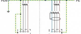
Joint suspension of rural telephone overhead cable and overhead lines is allowed if the following requirements are met:
1) the zero core of the SIP must be insulated;
2) the distance from the SIP to the overhead cable of the STS in the span and on the VLI support must be at least 0.5 m;
3) each VLI support must have a grounding device, and the grounding resistance must be no more than 10 Ohms;
PEN must be performed
- conductor;
5) the supporting rope of the telephone cable, together with the metal mesh outer cover of the cable, must be connected to the ground electrode of each support by a separate independent conductor (descent).
Type of power line and voltage, how to determine visually
What voltage is in the power line, and accordingly, what are the parameters of the zone, will be found out at the local power supply. You can roughly determine the characteristics by analyzing the appearance of the high-voltage line. Security zone of 10 kV and 0.4 kV power lines are the most common in populated areas.
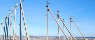
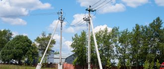
These overhead lines are usually located in cities, equipped with SIP or aluminum wire on relatively low supports with oversized insulators - white, brown, glass (transparent). Overhead lines with 10 kV and more are equipped with large insulators, often they are brown ceramic, the height of the support is about 9 m. Lines with 0.4 kW also have a security gap, but much smaller, up to 2 m.
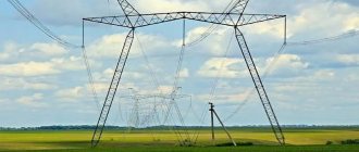
“Aerial towers” of 35–750 kV and more are the highest and largest supports, usually located on the outskirts of populated areas. In the forests, special clearings are cut down for them, with a width equal to the protective zones, however, as well as for other types of power lines. Towers for 35, 110, 220 kV are equipped with one core per phase, and then, according to power options, respectively, 300 - 2, 500 - 3, 750 - 4 or 5. Insulating garlands differ in the number of “plates”: 35 kV - 3 or 5 pcs., 110 - 6 or 8, 220 - 10 or 15, 500 and 750 - from 20.
Sagging standards
Let's consider the standards of the PUE chapters 2.4 and 2.5 in relation to the sagging of high voltage overhead lines.
As can be seen from the tables, the distance from the ground to the power line, as well as between wires and other objects, depends on the voltage value. For 380 volt networks, sag standards according to paragraph 2.4 of the PUE are as follows:
- Above the pedestrian area the height is not lower than 3.5 meters, and above the roadway this distance should be at a height of not lower than five meters; the input branch can be made at a height of 2.5 meters for the SIP wire.
- For lines with uninsulated conductors, the height is not less than three and a half meters above the pedestrian area, and not less than 6 meters above the roadway, a branch is allowed to be made at least 2.75 meters.
- When passing SIP near buildings, the distance from the cable to the balcony is at least one meter and at least twenty centimeters from the wire to the blank wall.
- In the case of uninsulated conductors, the distance from windows, terraces and balconies is at least one and a half meters and at least one meter along a blank wall.
- It is strictly prohibited to place overhead lines with uninsulated conductors above buildings for safety reasons.
Norms for wire sag from pole to house
What is prohibited in power transmission line protection zones
Within the boundaries of the protective and sanitary space, actions that threaten the normal operation, the stability of the operation of lines, during which a danger is created for people, for the operability of the facility, or the possibility of fires, are strictly prohibited.
Directly prohibited work in the security zone of power lines (we will indicate the general list according to GOST; in R. III of Resolution 160 it is more detailed):
- placement of objects with fuels and lubricants, flammable liquids, flammable liquids;
- landfills;
- events related to explosions;
- starting a fire;
- discharge, discharge of caustic, corrosive mixtures, fuels and lubricants;
- throwing, approaching objects to supports, wires;
- you cannot climb on structures;
- any actions and stay in a segment with a special regime during thunderstorms or extreme weather.
What is prohibited without the consent of the service organization (work is highlighted separately as such, which is possible, but with the consent of the responsible enterprises, according to Resolution No. 160, paragraph 10):
- construction and installation activities, watering, planting, cutting down, as well as storing feed, fuel, etc. It is forbidden to develop roads for vehicles and machinery with a height exceeding 4.5 m;
- if the installation is underground, then excavation work and leveling using earth-moving equipment are prohibited;
- For underwater lines, activities affecting the bottom soil, arrangement of berths, movement with loose anchors, trawls, etc. are prohibited. Watering places and the allocation of fishing areas are prohibited;
- for overhead power lines, work with lifting and retractable structures is permitted if the gap from the housing, transforming segments, and objects being lifted to the closest wire is not less than according to table. 2 GOST.
Irrigation works
In GOST, irrigation works are highlighted as separate points, since they pose an immediate danger due to the increased conductive properties of water in any of its forms (splashes and even sprayed small drops). Such activities are permissible in any weather, if the stream is outside the protected space, and also if it enters it, but does not rise above 3 m from the ground.
10.3. Gas industry
10.3.1. Hydrogen-cooled substations are provided with imported hydrogen and carbon dioxide. Own electrolysis installations are not being built at the substation.
10.3.2. The SC is supplied with hydrogen and carbon dioxide centrally from receivers. To receive and charge cylinders with hydrogen and carbon dioxide, a mechanized receiving and dispensing point (warehouse) is constructed at the substation, where ramps with cylinders and receivers are located in order to provide hydrogen for twenty-day operating consumption and a single filling of one CV with the largest volume.
The estimated daily consumption of hydrogen in one SC is assumed to be 5% of the total volume of gas in the machine body.
The minimum supply of carbon dioxide at the substation must be equal to three times the filling volume of one substation. The air for purging the compressor is taken from the substation air management system or from an independent compressor.
10.3.3. Hydrogen, carbon dioxide and compressed air are supplied to the SC through separate pipelines, laid openly on the same racks, with the pipelines arranged (from top to bottom): air-hydrogen-carbon dioxide.
The compressed air pipeline is connected to the SC with a flexible hose. It is allowed to lay carbon dioxide and hydrogen pipelines in cable ducts or trays, provided that seamless steel pipes are used.
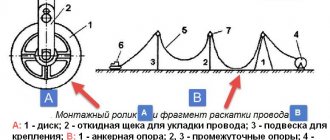
Installation
The rules for installing reinforced concrete supports are determined by GOSTs and SNiPs and are the same for both Moscow and other regions of Russia.
The support is assembled on a flat area cleared of foreign objects. For heavy structures, 35 kV and more attract riggers.
Most often, installation is carried out using technological maps, which contain the sequence of operations, the necessary devices, and the layout of parts (crossbars, traverses, racks).
The procedure for assembling single-post supports made from vibrating racks for power lines up to 10 kV:
- In order to secure the traverse and the grounding descent, the top of the product is raised. The braces and traverses are put on the bolts, the nuts are installed and tightened.
- Before installing the insulators, polyethylene caps are filled. The insulators are mounted and the nuts are cored.
- At the end, a stencil poster is installed, where the year of installation and serial number are indicated.
The supports are lifted using a crane, helicopter or by building up. Before installation, the correct preparation of the foundation and pits is checked.
For different lines, supports of different types and sizes are used.
Overhead lines up to 1 kV
On overhead lines less than 1 kV, the following supports are installed:
- single-column free-standing unified intermediate;
- A-shaped end, anchor, corner;
- single-post with struts;
- prefabricated from vertical posts installed side by side.
It is possible to assemble and install reinforced concrete supports from vibrating racks, which are made to hang 2-4 radio wires and 2 to 9 overhead line wires.
Such structures have steel traverses. They are also used as lighting supports, placing lamps, brackets for branches, and cable sleeves on them.
Overhead lines up to 10 kV
For overhead lines from 6 to 10 kV, installation of single-column products with struts and intermediate, anchor, end and corner - A-shaped products is carried out.
Structures made from vibrating START poles have a traverse, which is made for hanging 3 wires up to 120 mm² made of aluminum.
On anchor and corner single-post supports with struts, steel traverses are placed for the wires of each phase.
On intermediate single-post supports made of centrifuged posts, apical pins and traverses made of wood 80*100 mm are placed.
Overhead line 35-500 kV
On lines of 35 kV and above, portal and single-column free-standing supports unified with guy wires are used.
Their structural parts are cable supports, traverses and pillars, which have asphalt-bitumen waterproofing.
To prevent moisture from entering the rack, plug covers are installed, the bottom of which is an additional way to increase the support area and the strength of the structure in the ground.
There are holes in the upper part of the post for attaching traverses. The grounding slope is laid inside the concrete.
The coupling fittings (brackets and earrings) are secured using rollers, clamps and special brackets installed in the holes provided in the cable stands and traverses. Metal cable supports are attached to the poles with clamps.
Portal single-column supports with metal traverses are installed on 330-500 kV power lines as intermediate ones.
For a 35-220 kV line, intermediate structures with cylindrical and conical posts, 2- or 1-circuit, free-standing single posts are used.
Anchor corner structures are made in the form of reinforced concrete products with guys for 35-110 kV overhead lines.
Danger of living near power lines
It may seem that the Rules for Establishing Security Zones are aimed mainly at protecting power grid facilities. But initially, the boundaries of the protection zones were determined based on the danger of the impact of power lines on human health.
The electric field has an extremely negative effect on the human body. The cardiovascular and nervous systems are primarily affected. However, this effect is felt only after a long stay. Staying near power lines for a short time is quite safe, although there are people with high sensitivity who may feel unwell even after a short stay near power lines.
There are also types of allergies in which a person may experience an epileptic-like reaction when exposed to a high-level electric field.
The safe distance at which people can stay for a long time without harm to their health is defined as the one at which the level of electric field strength does not exceed 1 kV/m. This is how the boundaries of security zones of overhead power lines are calculated depending on the design voltage.
However, the owner of a land plot through which the security zone of an overhead power line runs should not think that he is completely safe outside this zone.
The fact is that the above calculations take into account only the electric field. And most power lines conduct alternating current at industrial frequency, which results in the appearance of an electromagnetic field.
In Russia, studies have not been carried out on the impact of magnetic fields on the human body, but the results of foreign experiments and observations have shown that the magnetic field has a negative effect on human health, causing disorders of the nervous and immune systems, as well as increasing the risk of cancer.
At the same time, safe distances from power lines, where you can stay for a long time without harm to your health, are several times higher than established sanitary standards.
It follows that any areas where power lines run are unsafe for living. In this case, the harm caused will not be noticeable immediately, but will accumulate and lead to deterioration of health gradually.
The creation of a power line security zone is an action aimed at increasing the safety of all parties. And violation of the rules in force in this zone can lead to unpleasant consequences not only for the violator’s wallet, but also for his health and even life.
Since the use of land with such encumbrance is very limited, it may be advisable to avoid acquiring such plots.
When purchasing land, you must carefully study the cadastral documents for it, and if possible, inspect the site in person - a power line not included in the documents may later turn out to be an extremely unpleasant surprise that will poison the further use of the purchased territory.
If such a situation does occur, it is worth trying to negotiate with the network company to move the power lines outside the site. However, one must understand that such measures are very costly, and a court decision to postpone may be necessary if the installation of power lines was carried out with violations.
Determining voltage in power line wires
If it is not possible to obtain information about the voltage in the wire lines adjacent to the site, you can contact local authorities and obtain this data, on the basis of which it is possible to plan construction stages.
To determine the voltage yourself and understand how many meters you need to retreat, you can, firstly, count the number of wires connected in a bundle that the power line support carries.
Next to the road
Dependence of voltage on the number of wires:
- 2 wires – 330 kV;
- 3 wires – 500 kV;
- 4 wires – 750 kV.
Small voltage values are calculated by summing the number of insulators.
Dependence of voltage on the number of insulators:
- 3–5 insulators – 35 kV;
- 6–8 insulators – 110 kV;
- 15 insulators – 220 kV.
Electromagnetic field propagation diagram
If the calculations correspond to these data, then you can maximally protect yourself and the guests of your residential building, cottage or summer cottage from electromagnetic radiation, as well as from other possible dangerous risks.
Underground power lines
Some organizers are considering laying power lines underground. Then it becomes possible to build anything on this site. However, during construction it is worth remembering that in any case it will be necessary to leave some space for repair work, which will have to be carried out in case of emergency situations on the line. The standard distance from the fence to the power line in the “underground” version is only one meter.
Underground connection of the houseA significant difference between overhead and underground electricity transmission lines is their cost. Underground lines are much more expensive (several times) and are widely used in cities and industrial enterprises.
Cables are laid in boxes, tunnels and trenches at a depth of up to one meter. The most ergonomic solution would be to lay six cables at a distance of 30 centimeters in one trench.
Here you can find out the distance from the house to the trees.
What is it for
Correct determination of the span between lighting supports will allow you to achieve:
- creation of full-fledged lighting provision throughout the entire section of the roadway;
- high-quality lighting of sidewalks, squares and parks;
- creating conditions for the safe movement of vehicles on roads, as well as people along sidewalks and pedestrian crossings;
City street lighting
- reducing the level of illegal actions, which, according to statistics, are committed in poorly lit areas of streets, parks and squares;
- maintaining the city's infrastructure at the required level.
If an error has crept in at least somewhere, then the external lighting system will not be able to perform its direct functions at the proper level.
The distance at which power lines are installed to the fence
In the matter of building a house and equipping its territory, many issues are important. This includes the distance from the power line to the fence, which everyone who has started building a fence for their private plot should know about. The safety of those who come to the territory on vacation or permanently reside on the territory depends on the correct calculation of the distance from power lines to the fence of a private house.
Diagram with dimensions of the location of the fence from the power line
Important points
A person uses electricity all the time, be it at home, in the country or in the office. But few people delve into the fact that power lines not only supply a useful resource, but can also be harmful due to magnetic fields, and in case of failures they become unsafe for humans. It is imperative to adhere to the established rules, which indicate the required distance from the support to the fence of a residential private house for the following reasons:
- To preserve the health of building occupants.
- In order not to suffer from the effects of airborne electromagnetic fields that have a detrimental effect on the human brain.
- In the security zone of power lines, where the voltage level is especially dangerous for humans, the issue of locating residential buildings is especially acute. If the level of danger is off the charts, the area is fenced off with an industrial fence and a ban on construction in this area is put in place.
Power line protection zone diagram
Therefore, SNiP establishes distances from power lines to the fence of a house not just so that people do not receive fines for violations, but for the safety of the population of cities and villages.
The sanitary standards related to power lines clearly and in detail describe at what distance from power lines fences can be installed. This distance depends on the voltage level in the wires. In places of special tension, which are specially equipped, there are sanitary zones, near which it is prohibited to place fences and build residential buildings.
Safe distance from power lines
A requirement is established for the distance from the fence at the dacha to the place where the power line support is located, based on the voltage class.
Some owners of private plots turn to city or rural self-government bodies in order to obtain information about the voltage class in power lines located near their summer cottage.
Of course, not knowing how to determine the voltage level in the wires, it is better to do just that, so as not to unwittingly become a violator of SNiP requirements and endanger the residents of a private plot.
However, there is a method by which you can independently determine the voltage level in power poles.
Diagram of voltages in power lines of various types
If the voltage is very small, then it can be determined by counting the insulators.
How to increase your security level
Even having fully complied with all the norms and requirements regarding the distance of the fence from the poles through which electricity passes, houses built near power lines are still at risk in unforeseen situations and must protect their private sectors. This can be done in the following ways:
- Select a roof with grounding for the construction of the house,
- Install reinforcing mesh inside the wall structure. This solution will help reduce the risk of penetration of harmful electromagnetic waves into the living space,
- To increase the level of safety for home residents, fruit trees should be planted at a horizontal distance of at least 2 meters from power lines.
Minimum permissible distances from trees to power lines
Recommendations
The requirements in SNiP are prescribed primarily for the safety of people, and not to fulfill the wishes of self-government bodies. Therefore, you should not neglect safety rules, especially when it comes to electrical voltage.
It is worth paying maximum attention to calculations at what distance it is safe to install a fence from power lines. Only a properly installed fence will provide comfort and limit the residents of a private plot from troubles and danger.
Sanitary zones
Electrical transmission lines emit electromagnetic floors that negatively affect human health, plants and animals. Under power lines, starting from 330,000 V, sanitary zones are created. Their width will be 10 meters on all sides. Measurements are taken from the projection of the outermost wire onto the ground. It is forbidden to string high-voltage wires through the air at any height above railway tracks and gas pipelines. If there is a break, there is a high chance of an accident. A gas pipeline running on the ground should under no circumstances intersect with overhead electrical transmission lines. For the crossing there must be underground cable conduction with grounding of the installations at the point of exit and entry of the line. Electricity needs to be supplied to cities and towns through electrical transmission lines.
There may be a parallel pipeline, streets with houses and a highway nearby. The norm for the distance of power lines from them should be from 5 to 10 meters, and the standards are determined by the width of the san. zones. The distance must be calculated taking into account the boundaries of the dacha sector site. There must be a distance of at least 100 meters to residential buildings if the voltage is greater than 35,000 V. All requirements for distances between power lines are described in GOST R 21.1101-2009. On the basis of this regulatory document, all calculations are performed and designs of electrical transmission lines are developed.
Reinforced concrete power transmission line supports - classification by purpose
The classification of reinforced concrete supports by purpose does not go beyond the types of supports standardized in GOST and SNiP. Read in detail: Types of supports by purpose, but here I will briefly remind you.
Intermediate concrete supports
needed to support cables and wires. They are not subject to longitudinal or angular tension loads. (marking P10-3, P10-4)
Anchor concrete supports
provide retention of wires during their longitudinal tension. Anchor supports must be installed at the intersection of power lines with railways and other natural and engineering barriers.
Corner supports
are placed at the turns of the power line route. At small angles (up to 30°), where the tension load is not large and if there is no change in the cross-section of the wires, angular intermediate supports (IP) are installed. At large rotation angles (more than 30°), corner anchor supports (CA) are installed. At the end of the power line, anchors, also known as end supports, are placed (A). For branches to subscribers, branch anchor supports (OA) are installed.
Types of reinforced concrete pillars
Reinforced concrete products designed for the transmission or distribution of electrical energy come in voltages from 0.38 to 35 kV. Power transmission towers are subject to torsional loads, a large number of lighting elements, a mass of wires, and lateral loads. The bending of lighting supports SV 9.5 is 19.6 kN*m, and SV 110 is 35 kN*m. Based on design calculations and regulatory tables, the volume of which is several volumes, the compliance of the required electrical supports and their application are determined.
According to their intended purpose, reinforced concrete supports for electric power transmission lines are represented by the following classification:
There are several types of such products that differ in purpose.
- Anchor. Installed at various intersections, as well as where the number, grades or cross-section of wires change. Such electrical supports must be installed if a power line intersects with an overhead railway line and other obstacles.
- Angular. Installed if the angle of rotation of the air line is quite large. At angles up to 30°, intermediate types of supports are used.
- End Mounted at the ends of the line. Wires go from them to substations.
- Transitional. Used to move cables through various obstacles and structures.
- Transpositional. With their help, they change the order of the wires on the poles.
- Branches. They create branches of power lines, for example, across rivers.
- Cross. Used as an overlap for cables.
One of the types of such products is portal. Concrete supports are:
- portal (free arrangement) with internal connections and with suspenders;
- single or multi-post, free-standing or guyed.
2.5.238
When crossing an overhead line with an underground communication cable and a power supply (or with an underground cable insert), the following requirements must be met:
1) the angle of intersection of overhead lines up to 500 kV with LS and LPV is not standardized, the angle of intersection of 750 kV overhead lines with LS and LPV should be as close as possible to 90°, but not less than 45°;
2) the distance from underground cables LS and LPV to the nearest ground electrode of an overhead line support with voltage up to 35 kV or its underground metal or reinforced concrete part must be at least:
in populated areas - 3 m;
in uninhabited areas - the distances given in Table 2.5.26.
Table 2.5.26 Shortest distances from underground cables LS (LPV) to the nearest ground electrode of the overhead line support and its underground part
| Equivalent earth resistivity, Ohm m | Shortest distance, m, at overhead line voltage, kV | ||
| Up to 35 | 110-500 | 750 | |
| Up to 100 | 10 | 10 | 15 |
| More than 100 to 500 | 15 | 25 | 25 |
| More than 500 to 1000 | 20 | 35 | 40 |
| More than 1000 | 30 | 50 | 50 |
The distance from underground LAN and LPV cables to the underground part of an ungrounded wooden support of an overhead line with voltage up to 35 kV must be at least:
in populated areas - 2 m; in cramped conditions, the specified distance can be reduced to 1 m, provided that the cable is laid in a polyethylene pipe at a length on both sides of the support of at least 3 m;
in uninhabited areas: 5 m – with an equivalent earth resistivity of up to 100 Ohm m; 10 m – with equivalent earth resistivity from 100 to 500 Ohm m; 15 m – with equivalent earth resistivity from 500 to 1000 Ohm m; 25 m – with an equivalent earth resistivity of more than 1000 Ohm m;
3) the distance from the underground cables of LAN and LPV to the nearest ground electrode of the overhead line support of 110 kV and above and its underground part must be no less than the values given in Table 2.5.26;
4) when laying an underground cable (cable insert) in steel pipes, or when covering it with a channel, an angle, or when laying it in a polyethylene pipe, closed on both sides from the ingress of earth, at a length equal to the distance between the overhead line wires plus 10 m with on each side from the outermost wires for overhead lines up to 500 kV and 15 m for overhead lines 750 kV, it is allowed to reduce the distances indicated in Table 2.5.26 to 5 m for overhead lines up to 500 kV and up to 10 m for 750 kV.
In this case, the metal covers of the cable should be connected to a pipe or other metal protective elements. This requirement does not apply to optical cables and cables with an external insulating hose, including those with a metal sheath. The metal covers of the cable insert must be grounded at the ends. When reducing the distances between the cable and the overhead line supports specified in Table 2.5.26, in addition to the given protection measures, it is necessary to install additional protection against lightning strikes by lining the supports with cables in accordance with the requirements of regulatory documentation for the protection of cables from lightning strikes;
5) instead of using a channel, angle or steel pipe, when constructing a new overhead line, it is allowed to use two steel cables with a cross-section of 70 mm, laid symmetrically at a distance of no more than 0.5 m from the cable and at a depth of 0.4 m. The cables must be extended on both sides at an angle of 45° to the route towards the overhead line support and grounded to a resistance of no more than 30 Ohms. The relationship between the length of the cable outlet and the grounding resistance must correspond to the values and given in Table 2.5.27;
Table 2.5.27 Resistance of grounding conductors when protecting LAN and LPV cables at the intersection with overhead lines
What material are the pillars made of?
High-voltage transmission lines comprise a complex metal structure, the shape of which depends on the voltage in the wires and the number of lines.
Poles are installed under power lines up to 35 kV. They can be made of different materials:
- tree;
- concrete;
- metal.
Intermediate wooden power transmission poles are mounted on reinforced concrete pillars - foundations. To protect it from destruction, the wood is impregnated with special compounds. The size of the deflection to the lowest point can be up to 4.5 m when located in a field, at a distance of at least 100 m from the private sector and roads. For high-voltage lines up to 35 kV, the wooden part of the poles has a height of 8.5 m.
Cable installation
Distance between them:
- holiday village - from 30 to 50 m;
- urban settlement – up to 70 m;
- city, private sector – up to 60 m.
A cottage, garage and residential building can be located from the power line at a distance of 5 m. If the distance from the pole to the entry point is more than 20 m, it is necessary to install an additional pole.
Concrete anchor supports look like a skewed letter A. The main post is level, the anchor is (support) inclined. The distance between reinforced concrete power line racks at ground level is more than one meter. The height to the bottom insulator is 7800 mm, the gap between the hangers (wires) is 1000 mm.
Minimum distance diagram
The maximum permissible sag of wires is at a height of 7600 mm from the ground. Special devices provide tension on the wire. Anchor supports are used mainly as end and corner supports.
Steel supports are used for high-voltage lines with voltages above 35 kV. They are manufactured in the following types:
- single-post;
- portal.
Single-post power transmission line supports have a tower design with a sharp top.
They are installed on a concrete foundation. Height – from 9 to 23 m. Distance between suspension points – from 4.8 m. Insulators are located on remote brackets on both sides of the support. They can be installed between distribution points and large consumers such as cities and industrial enterprises.
Underground connection
Installation in the private residential sector is extremely rare. Power lines can run between streets, while maintaining the width of the sanitary zone, as required depending on the voltage: 5 or 10 m in each direction from the outermost wires.
The distance between single-post metal supports ranges from 200 m within populated areas and up to 400 m on flat terrain away from all buildings and highways.
What additional methods of protection are there?
To increase protection from the harmful effects of fields generated by power lines, additional protection options are provided. These include:
- Shielding devices for voltages from 10 kV.
- Roofs made from metal tiles or corrugated sheets should be grounded. The roof is grounded only if the distance from it to the power lines is small.
- The presence of reinforcing mesh - the kind that is laid in reinforced concrete walls.
At present, the harmful effects of power lines on human health have not been officially confirmed. Such studies have not been conducted in Russia. But this does not mean that the problem does not exist.
Possible damage zone in an accident
According to the observations of foreign scientists, a huge number of people who live or work in close proximity to high-voltage structures experience their negative influence, they often feel unwell. In addition, the risk of nervous ailments and the development of cancer increases.
Harm from electromagnetic radiation
Few people think about the dangers of emitted magnetic waves that come from high-voltage lines. To prevent such carelessness from causing health problems, it is necessary to study the details of the correct proximity to power lines.
Before tackling the issue of installing a power pole, it is necessary to study all the nuances so as not to cause harm to the body.
In addition, there are standards established by Russian legislation. The distance from the pole to the house is clearly regulated by sanitary standards (SanPiN) and construction standards (SNiP). It is not recommended to ignore them and risk the health of your household.
Modern people are already exposed to a large load of radio wave radiation created by various household and computer equipment. When talking, mobile phones are in close proximity to the brain, and this negatively affects its normal functioning.
When constructing residential and non-residential structures in the area where electrical supply lines pass, the permitted distance must be maintained. Even in the process of designing a facility, it is necessary to familiarize yourself with the terrain features and regulatory documentation. The health of the entire family will depend on how seriously a person takes this issue.
Distance between lamp posts, lighting supports
When installing lamp posts, lighting supports in the city, along the road, the distance between the outdoor lighting supports of the city is determined based on the number of lighting lamps installed on the support, their power and the height of the lamp installation above the road. The distance between reinforced concrete lighting poles when installing lamp poles along roads is determined using the same table. The calculation of the distance between lighting supports is based on road illumination standards. This calculation allows you to answer the questions: “How many meters are between the lamp posts?”, “What is the distance between the lamp posts?”, “What is the span between the lamp posts?”. The ratio of the pitch of lamps to the height of their suspension on streets and roads of all categories should be no more than 5:1 with one-sided, axial and rectangular placement of lamps and no more than 7:1 with a checkerboard placement pattern. The table shows the maximum distances between lighting supports, taking into account the required illumination of the roadway.
| Number and type of lamp, on one support | Lamp installation height, meter | Distance between lighting supports, m | Type of lighting lamppower, W | Installed lighting power per 1 km, kW |
| 4 X ZhKU 50-400-001 | 20 (VMO20, OGKS 20) | 65 | DNAT 400 | 30 |
| 1 X ZhKU 30-250-001 | 12 | 36 | DNAT 250 | 16,5 |
| 1 X ZHKU 40-250-001 | 12 | 36 | DNAT 250 | 16,5 |
| 1 X ZHKU 50-250-001 | 12 | 36 | DNAT 250 | 16,5 |
| 2 X ZhKU 40-250-001 | 12 | 31 | DNAT 250 | 19,5 |
| 2 X ZhKU 50-150-001 | 11,3 | 35 | DNAT 150 | 10 |
| 1 X ZhKU 30-250-001 | 12 | 39 | DNAT 250 | 15,5 |
| 1 X ZHKU 40-250-001 | 12 | 33 | DNAT 250 | 18 |
| 1 X ZHKU 50-250-001 | 12 | 45 | DNAT 250 | 13,5 |
| 1 X ZHKU 40-250-001 | 12 | 36 | DNAT 250 | 8 |
| 1 x ZHKU 30-150-001 | 12 | 39 | DNAT 150 | 9 |
| 1 X ZHKU 40-250-001 | 12 | 39 | DNAT 250 | 15,5 |
How many meters between the support and the road when installing lighting poles?
Electrical installation of outdoor lighting fixtures is carried out on street lighting poles, lighting masts, power line poles and other structures. To illuminate this or that part of the street, it is necessary to install an external lighting system in accordance with the standards for installing electrical poles.
Electrical installation of outdoor lighting poles must be carried out in accordance with the rules of the Electrical Installation Rules.
Minimum distance from the edge of the roadway to the lighting poles:
The installation of street lighting poles along roads, streets, and squares must be done at a distance of at least 1 meter from the road curb on main streets with heavy traffic, and lighting poles should be placed at a distance of at least 0.6 meters from the curb on other roads. This distance can be reduced to 0.3 meters in the absence of routes for urban transport and trucks, which is allowed by the standards. If there is no curb, the distance from the road to the lighting support must be at least 1.75 meters. In the territories of enterprises, the distance from the lighting support to the roadway is taken to be at least 1 meter. Lighting poles for streets and roads may be installed on the central dividing strip if its width is 5 m or more, as well as on a dividing strip 4 m wide if there is a stationary fence and the supports are placed in the alignment of this fence. The lighting support should not be located between the fire hydrant and the roadway (PUE standards prohibit). Lighting poles at intersections and junctions of streets and roads should be installed no closer than 1.5 m before the start of the curve, without disturbing the uniform structure of the pole installation line.
On curves of streets and roads with a radius in plan along the axis of the roadway from 60 to 250 m, metal lighting poles, if they are located on one side, should, as a rule, be placed on the outer side of the road; if it is impossible to place lighting poles on the outer side of the curve, it is allowed to place lamps on the inside side with an additional reduction in the pitch of the lighting supports. In lighting installations of transport junctions and city squares, it is allowed to use high supports (20 m and above) with an appropriate feasibility study and ensuring ease of maintenance of the lamps.
If the cable supply for external lighting is carried out by an overhead power line, then the distance from the lighting support to the balconies, terraces and windows of residential buildings must be at least 1 meter.
Basic principles of street lighting
To provide streets with light at night, poles have been used for many years. Over all these years, the most used materials for their manufacture have been wood, concrete, iron and reinforced concrete. This is due to their strength and longevity, especially for reinforced concrete. Many different areas of both residential and non-residential areas of a settlement need constant light at night, in particular:
- street sidewalks and pedestrian paths;
- carriageways for cars and highways;
- territories where various institutions are located;
- gas stations;
- car parks, etc.
High-quality street lighting Although the distance between lighting poles is the most important point during installation, it is still necessary to know and understand the essence and purpose of the structures for the lamps themselves. It has two components:
- The main part of the support is a pillar, which can vary in height. This is due to its function and location. Usually, when installing them in a village or city, the height is selected in such a way that the incident light forms peculiar cones on the ground that must intersect.
- A source that reproduces the luminous flux. This equipment is installed on top of lighting poles and can be of different shapes, wattages, etc. This factor depends on the location of the lighting line. For example, when arranging the illumination of highways, the use of lamps with powerful lamps is required, which, accordingly, increases the size of the lighting device itself. To illuminate recreation parks, squares and public gardens, you can use poles of shorter height and decorative light sources.
Types of poles for street lighting Very often, poles with lanterns perform not only a lighting function, but are also supports for holding various wires and power lines. In this case, the distance between them can be increased.
Connecting electricity from the pole to the house
Specialized companies are engaged in connecting the cable from the power pole to the distribution box of the house. Before contacting specialists, owners of private houses need to obtain permission from an organization that deals with the supply and connection of electricity. It is necessary to study all the requirements for connecting a private building to the electrical network.
To connect a home, it is necessary to prepare a complete description of the home electrical network with calculations of the power and mode of each pantograph. Based on this project, a permit will be issued.
Electrical installation work must be carried out by employees of the organization who have the appropriate license. Before starting work, you need to decide on the connection method. Today, there are overhead and underground methods for connecting electrical current.
Air way
This method of connecting the cable to the house is interesting because it takes a minimal amount of time and does not require large financial costs. To connect by air, for example, a wooden frame house, self-supporting insulated wires are used that will last at least thirty years. But according to eyeliner standards, not all private houses are suitable. The cable entry into the house must be located at least 2.75 m from the ground.
If the residential structure is below this mark, special racks should be installed. Such devices can have a straight or curved shape. The racks differ not only in shape, but also in the method of mounting on the wall:
Electrical energy is removed from sources using cables made from different materials. Copper wires are required in smaller sizes, but are significantly more expensive. Therefore, wiring from racks to a low-rise building or country house is mainly carried out using cable products with aluminum cores.
The distance from the foundation of a private house to a high-voltage pole should be no more than 10 meters. This applies not only to houses, but also to country houses and other residential buildings. If the actual length from the power line pole exceeds this value, then it is necessary to install an auxiliary support on a separate foundation.
The distance from the electric pole to the additional support post should not exceed 15 meters. The minimum distance from the outermost post to a residential building must be at least 1.5 meters to window openings and loggias; 1 meter is the minimum distance to the façade walls of buildings or foundations.
Experts carry out wiring of an electrical wire through the wall of a house built of wood using a steel pipe. If the structure is built of brick on a concrete foundation, then an ordinary plastic pipe is quite suitable for this purpose.
Closed method
Discharging the cable using the closed method through a trench dug underground requires more time and material resources. You will need about 15 meters more wires.
In this case, an additional agreement may be required to carry out earthworks in a certain location, which is also fraught with unnecessary financial costs.
Before you begin laying the cable, you should dig a trench and install protective insulation in the form of a polyethylene pipe. Laying in soil with increased chemical activity will require increased insulation protection. You can resort to using aluminum or lead sheathing.
Then you need to outline the path along which the trench will go. To use less insulating material and spend less physical effort digging a ditch, it is best to draw a trench directly from the power line to the site. But, unfortunately, this is not always possible. Departures from the direct road may be required under the following circumstances:
Once the route for laying the cable is determined, you need to dig a deep trench - about 70–80 cm. To ensure power supply to buildings under the soil, you need to use an armored cable with copper conductors. The cable insulation must be much stronger.
All underground work on installing wires from a power line pole to a residential building cannot be carried out with one’s own hands. This should be done by employees of special companies that have permission to provide this type of service. The underground method of supplying cables from a high-voltage source will increase the protective functions against harmful radiation from power lines.
How to install an electricity pole on a site
When electrifying a land plot, the owner needs to install power line supports. When carrying out this procedure, a number of rules and regulations must be observed, and all work must be coordinated with authorized government agencies.
Regulatory requirements for the installation of electricity poles
Standards for additional electric power transmission poles are regulated at the legislative level. The requirements are as follows:
- the distance between unprotected wires to balconies or windows is at least 1.5 m;
- the gaps between line conductors are at least 10 cm for spans less than 6 m, 15 cm for spans greater than 6 m;
- height of the connection point of power lines to a residential building - from 2.75 m;
- the height of the wires is 3.5 m above the ground and 6 m above the roadway, respectively;
- the electricity pole must be made of fire-retardant materials;
- materials used to make insulators are porcelain or glass.
Before installing the pole, you should understand the classification. There are four types:
- Anchor. Used in places with the highest load point, as it is intended for fastening lines.
- Intermediate. Such pillars are located between anchor ones. Wires are hung on them in the spaces between the fasteners.
- Angular. Used where lines turn. Depending on the size of the turn, either an intermediate or an anchor structure can be used.
- Terminal. Located at the end points of the line.
In addition to standard types of poles, there are specialized ones. This is a generalized name for pillars of non-standard configuration. They are used at intersections of power lines with railways, highways, buildings and structures. Such structures are not used in summer cottages.
Is approval required for installing poles?
To place a power line support and connect a private home to electricity, the owner must obtain permission. To coordinate the installation of electricity poles at the dacha, related equipment and further network connection, you need to contact the energy sales company at the site address.