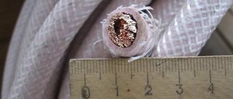
A computer local and Internet network is created using special cables. And in order to reduce the impact of various interferences, twisted pair cables are used, which are laid from the router to the computer or between PCs. Specialists of the portal “2 Schemes” will tell you in detail about the types of such cables, their pinout, installation and features of use. The cable design consists of 8 cores, which are twisted together and placed in a common braid. Usually 4 pair UTP cables are used, for example, these.
Types of color schemes for crimping LAN cables
According to the EIA/TIA-568 specification, there are several color schemes for crimping twisted pair lan cables (patch cords) into an RJ-45 connector to connect computers to a router, hub, switch, or connect two computers to each other.
What is the difference between a patch cord and a twisted pair cable? A patch cord, or as it is also called a patch cord, is designed to connect electronic devices to each other, for example, a computer with a hub, switch, or two computers with each other. To make a patch cord, you take a twisted-pair cable, the cores of which are made of stranded wire so that they do not break due to frequent kinks. To crimp such a cable, special RJ-45 connectors are used.
Types of cables for the Internet
Shielding provides better protection from electromagnetic interference, both external and internal, etc. The entire length of the screen is connected to a non-insulated drain wire, which unites the screen in case of division into sections due to excessive bending or stretching of the cable.
- Unprotected twisted pair (UTP - Unshielded twisted pair) - there is no protective shield around an individual pair, most often this is UTP category 5 and higher;
- Foil twisted pair (FTP - Foiled twisted pair) - also known as F/UTP, there is one common external shield in the form of foil;
- Protected twisted pair (STP - Shielded twisted pair) - there is protection in the form of a screen for each pair and a common external screen in the form of a mesh;
- Foil shielded twisted pair (S/FTP - Screened Foiled twisted pair) - an external shield made of copper braid and each pair in a foil braid;
- Unprotected shielded twisted pair (SF/UTP - Screened Foiled Unshielded twisted pair) - double external shield made of copper braid and foil, each twisted pair without protection.
Useful: Pinout, connection diagram and checking the VAZ ignition coil
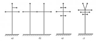
Types of power transmission towers
Depending on the method of hanging the wires, the supports are:
- intermediate, on which the wires are secured in supporting clamps;
- anchor type, used for tensioning wires; on these supports the wires are secured in tension clamps;
- corner ones, which are installed at the angles of rotation of overhead lines with wires suspended in supporting clamps; they can be intermediate, branch and corner, end, anchor corner.
On a larger scale, overhead line supports above 1 kV are divided into two types: anchor ones, which fully support the tension of wires and cables in adjacent spans; intermediate, not perceiving the tension of the wires or perceiving partially.
On overhead lines, wooden supports are used (Fig. 5L, b, c), new generation wooden supports (Fig. 5.1, d), steel (Fig. 5.1, e) and reinforced concrete supports.
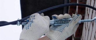
Crimping twisted pair with a screwdriver
You can crimp a network cable without a crimper. If you don’t have a special tool at hand, you can use a regular flat-head screwdriver.
You can really crimp it reliably with a screwdriver - there’s nothing complicated here, the main thing is to properly align the wires in advance so that they fit evenly and stay in the connector, and then carefully press the metal plates with a screwdriver, turning them over and placing the connector on a flat surface. You will clearly feel that the pressure is enough - the braid is broken and the wire is securely fixed. You need to press with the tool until the latch stops protruding beyond the edges of the connector. Only in this case will the electrical wire be securely fixed and secured.
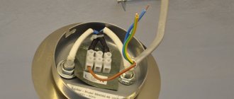
Technology of cable routing in the socket
Pinout of an RJ45 socket does not require any specialized equipment; you only need one tool - nail scissors or a small knife with a thin blade. Here is the sequence of actions:
- The top layer of the winding is cut off. The cut length is about 10 cm for ease of wiring.
- The twists of all pairs are unwound and the wires are aligned so that from the base of the top layer to the tips of the wires they do not intersect.
- Any socket has two color markings. “A” – cross connection, “B” – standard connection. According to the last marking, the RJ45 pinout is carried out.
- Having attached the base of the braid to the board, first the cores are inserted into the far connectors. Be sure to check the cable tension so that the distance from the braid to the clamp does not exceed 3 cm.
- Having secured the cable cores in the required connectors, crimping is performed. Holding the nail scissors so that the angle of the cutting guides is 45 degrees, you need to press on the core from above until you hear a characteristic metal click.
When installing a power outlet on a wall, the connectors should always face down. This protects the contacts from becoming clogged with dust and moisture, and when you quickly connect the cable from below, there is less chance of accidentally knocking down the socket on the wall.
Electrical laboratory » Questions and answers » PUE 7th edition » 2.5.220-2.5.230. Intersection and convergence of overhead lines with each other
Intersection and convergence of overhead lines with each other
2.5.220. The intersection angle of overhead lines (VLZ) above 1 kV with each other and with overhead lines (VLI) up to 1 kV is not standardized.
2.5.221. The intersection location should be chosen as close as possible to the support of the upper (intersecting) overhead line (VLZ). The distances from the wires of the lower (intersecting) overhead line to the supports of the upper (intersecting) overhead line horizontally and from the wires of the upper (intersecting) overhead line to the supports of the lower (intersecting) overhead line in the clear must be no less than those given in table. 2.5.23, as well as at least 1.5 m for overhead lines and 0.5 m for overhead lines.
Table 2.5.23. The smallest distance between the wires and supports of intersecting overhead lines
| Overhead line voltage, kV | Minimum distance from the wires to the nearest part of the support, m | |
| at the greatest deviation of wires | with the wires in the non-deviated position | |
| Up to 330 | 3 | 6 |
| 500 | 4 | 10 |
| 750 | 6 | 15 |
It is allowed to cross overhead lines and overhead lines with each other and with overhead lines (VLI) up to 1 kV on a common support.
2.5.222. The supports of the 500-750 kV overhead line, limiting the span of the intersection with the 500-750 kV overhead line, must be of the anchor type. Intersections of 500-750 kV overhead lines with 330 kV and lower overhead lines, as well as 330 kV and lower overhead lines with each other, are allowed to be carried out in spans limited by both intermediate and anchor supports. Single-post wooden supports of an intersecting overhead line, limiting the span of the intersection, as a rule, should be with reinforced concrete attachments. It is allowed to use single-post wooden supports without attachments and, as an exception, elevated wooden supports with wooden attachments.
2.5.223. When crossing a 500-750 kV overhead line with a 6-20 kV overhead line and an overhead line (VLI) up to 1 kV, the supports of the crossed overhead lines, limiting the crossing span, must be of the anchor type, the wires of the crossed overhead lines in the crossing span must be: steel-aluminum with a cross-sectional area of at least 70 mm2 for aluminum - for overhead lines 6-20 kV; steel-aluminum with a cross-sectional area of at least 70 mm2 for aluminum or from a heat-strengthened aluminum alloy with a cross-sectional area of at least 70 mm2 - for overhead line 6-20 kV; aluminum with a cross-sectional area of at least 50 mm2 - for overhead lines up to 1 kV; SIP harness without a supporting neutral wire with a cross-sectional area of the phase conductor of at least 25 mm2 or with a supporting wire made of heat-treated aluminum alloy with a cross-sectional area of at least 50 mm2. Wires in crossing spans must be secured to supports using: suspended glass insulators - for overhead lines (VLZ) 6-20 kV; pin insulators with double fastening to them - for overhead lines up to 1 kV; tension anchor clamps - for VLI.
2.5.224. On intermediate supports of a crossing overhead line with supporting garlands of insulators, the wires should be suspended in blind clamps, and on supports with pin insulators, double wire fastening should be used. On intermediate supports of an existing 750 kV overhead line, limiting the span of intersection with newly constructed overhead lines up to 330 kV, as well as on existing overhead lines up to 500 kV with a cross-sectional area of the aluminum part of the wires of 300 mm2 or more, when constructing other overhead lines under them, it is allowed to leave clamps with a limited strength of seals and drop-out clamps.
2.5.225. Wires of higher voltage overhead lines, as a rule, should be located above the wires of crossed lower voltage overhead lines. It is allowed, as an exception, to pass overhead lines of 35 kV and higher with wires with a cross-sectional area of the aluminum part of 120 mm2 or more over the wires of higher voltage overhead lines, but not higher than 220 kV.* In this case, the passage of lower voltage overhead lines over the wires of double-circuit overhead lines of higher voltage is not allowed allowed.
___________________ * In cities and urban-type settlements, the passage of overhead lines or overhead lines with insulated wires with a voltage of up to 1 kV is allowed over the wires of an overhead line with a voltage of up to 20 kV.
2.5.226. The intersection of 35-500 kV overhead lines with double-circuit overhead lines of the same voltages, which serve to supply power to consumers that do not have backup power, or with double-circuit overhead lines, the circuits of which are mutually redundant, should, as a rule, be carried out in different spans of the crossing overhead line, separated by an anchor support. The intersection of 750 kV overhead lines with such overhead lines can be carried out in one span, limited by both anchor and intermediate supports. In sections of a cramped route, the intersection of overhead lines with wires with a cross-sectional area of the aluminum part of 120 mm2 or more with double-circuit overhead lines can be carried out in one span of the crossing overhead line, limited by intermediate supports. In this case, on the supports that limit the span of the intersection, double-circuit supporting garlands of insulators with separate fastening of the circuits to the support must be used.
2.5.227. The shortest distances between the nearest wires (or wires and cables) of intersecting overhead lines should be taken no less than those given in table. 2.5.24 at an air temperature of plus 15 °C without wind. For intermediate span lengths, the corresponding distances are determined by linear interpolation. The distance between the nearest wires of the crossing and crossed 6-20 kV overhead lines, provided that at least one of them is made with protected wires, at a temperature of plus 15 ° C without wind, should be at least 1.5 m.
Table 2.5.24. The shortest distance between wires or wires and cables of intersecting overhead lines on metal and reinforced concrete supports, as well as on wooden supports in the presence of lightning protection devices
| Span length of the crossing overhead line, m | Minimum distance, m, at a distance from the intersection to the nearest overhead line support, m | |||||
| 30 | 50 | 70 | 100 | 120 | 150 | |
| When crossing 750 kV overhead lines with each other and with lower voltage overhead lines | ||||||
| Up to 200 | 6,5 | 6,5 | 6,5 | 7,0 | — | — |
| 300 | 6,5 | 6,5 | 7,0 | 7,5 | 8,0 | 8,5 |
| 450 | 6,5 | 7,0 | 7,5 | 8,0 | 8,5 | 9,0 |
| 500 | 7,0 | 7,5 | 8,0 | 8,5 | 9,0 | 9,5 |
| When crossing 500-330 kV overhead lines with each other and with lower voltage overhead lines | ||||||
| Up to 200 | 5,0 | 5,0 | 5,0 | 5,5 | — | — |
| 300 | 5,0 | 5,0 | 5,5 | 6,0 | 6,5 | 7,0 |
| 450 | 5,0 | 5,5 | 6,0 | 7,0 | 7,5 | 8,0 |
| When crossing 220-150 kV overhead lines with each other and with lower voltage overhead lines | ||||||
| Up to 200 | 4 | 4 | 4 | 4 | — | — |
| 300 | 4 | 4 | 4 | 4,5 | 5 | 5,5 |
| 450 | 4 | 4 | 5 | 6 | 6,5 | 7 |
| When crossing 110-20 kV overhead lines with each other and with lower voltage overhead lines | ||||||
| Up to 200 | 3 | 3 | 3 | 4 | — | — |
| 300 | 3 | 3 | 4 | 4,5 | 5 | — |
| When crossing 10 kV overhead lines with each other and with lower voltage overhead lines | ||||||
| Up to 100 | 2 | 2 | — | — | — | — |
| 150 | 2 | 2,5 | 2,5 | — | — | — |
The vertical distance between the nearest wires of the crossing overhead line and the crossed overhead line at an air temperature of plus 15 ° C without wind must be at least 1 m. It is allowed to maintain the supports of crossed overhead lines up to 110 kV under the wires of crossing overhead lines up to 500 kV, if the vertical distance from the wires of the crossing The overhead line to the top of the support of the crossed overhead line is 4 m more than the values given in the table. 2.5.24. It is allowed to maintain the supports of crossed overhead lines up to 150 kV under the wires of crossing 750 kV overhead lines, if the vertical distance from the wires of the 750 kV overhead line to the top of the support of the crossed overhead line is at least 12 m at the highest air temperature.
2.5.228. The distances between the nearest wires (or between wires and cables) of intersecting overhead lines of 35 kV and above are subject to additional verification for the conditions of deflection of the wires (cables) of one of the intersecting overhead lines in the intersection span at wind pressure in accordance with 2.5.56, directed perpendicular to the axis of the span of this overhead line, and non-deviated position of the wire (cable) of the other. In this case, the distances between the wires and cables or wires must be no less than those indicated in the table. 2.5.17 or 2.5.18 for conditions of the highest operating voltage, the air temperature for non-deviated wires is taken according to 2.5.51.
2.5.229. On overhead lines with wooden supports that are not protected by cables, on the supports that limit the crossing spans, protective devices must be installed on both intersecting overhead lines. The distances between the wires of intersecting overhead lines must be no less than those given in table. 2.5.24. On the supports of overhead lines of 35 kV and below, when crossing them with overhead lines of 750 kV and below, it is allowed to use IP. At the same time, automatic restart must be provided for 35 kV overhead lines. Spark gaps on single-post and A-shaped supports with wooden traverses are made in the form of one grounding descent and end with bands at a distance of 75 cm (along the tree) from the point of attachment of the lower insulator. On U- and AP-shaped supports, grounding slopes are laid along two pillars of the supports to the traverse. On overhead lines with wooden supports not protected by cables, when crossing them with a 750 kV overhead line, metal parts for fastening wires (hooks, pins, heads) must be grounded on supports limiting the span of the intersection, and the number of hanging insulators in the garlands must correspond to the insulation for metal supports In this case, protective devices must be installed on the supports of 35-220 kV overhead lines. If the distance from the intersection to the nearest supports of intersecting overhead lines is more than 40 m, it is allowed not to install protective devices, and grounding of wire fastening parts on the supports of overhead lines of 35 kV and above is not required. Installation of protective devices on intersection supports is not required: for overhead lines with metal and reinforced concrete supports; for overhead lines with wooden supports at a distance between the wires of intersecting overhead lines, not less than: 9 m - at a voltage of 750 kV; 7 m - at voltage 330-500 kV; 6 m - at voltage 150-220 kV; 5 m - at voltage 35-110 kV; 4 m - at voltages up to 20 kV. The resistance of grounding devices of wooden supports with protective devices must be taken in accordance with Table. 2.5.19.
2.5.230. When running in parallel and bringing overhead lines of one voltage closer to each other or with overhead lines of other voltages, the horizontal distances must be no less than those given in table. 2.5.25 and accepted over higher voltage overhead lines. The specified distances are subject to additional verification: 1) to ensure that the neutral displacement does not exceed more than 15% of the phase voltage in normal operation of an overhead line up to 35 kV with an isolated neutral due to the electromagnetic and electrostatic influence of higher voltage overhead lines; 2) to exclude the possibility of development of resonant overvoltages in the off position of 500-750 kV overhead lines equipped with compensating devices (shunt reactors, synchronous or thyristor static compensators, etc.). The degree of compensation for the working capacity of the line, the distance between the axes of the overhead line and the length of the approach sections must be determined by calculations.
Table 2.5.25. The smallest horizontal distance between overhead lines
| Overhead line sections and distances | Shortest distance, m, at overhead line voltage, kV | ||||||||
| Up to 20 | 35 | 110 | 150 | 220 | 330 | 500 | 750 | VLZ | |
| Sections of the unconstrained route, between the axes of overhead lines | Height of the highest support* | 3 | |||||||
| Sections of cramped routes, approaches to substations: | |||||||||
| between the outer wires in a non-deviated position; | 2,5 | 4 | 5 | 6 | 7 | 10 | 15 | 20** | 2 |
| from the rejected wires of one overhead line to the nearest parts of the supports of another overhead line | 2 | 4 | 4 | 5 | 6 | 8 | 10 | 10 | 2 |
* At least 50 m for 500 kV overhead lines and at least 75 m for 750 kV overhead lines. ** For two or more 750 kV overhead lines, the phasing of adjacent outer phases must be different.