Main characteristics of thermal relays
The main characteristics of a thermal relay taken into account when choosing the appropriate option:
- Rated protection current
. Selected according to the rated load current. The rated current of the thermal relay must be one and a half times higher than In of the protected motor. - Interval for adjusting
the operating current setting. - The circuit voltage and the nature of the current
are constant or alternating. If the voltage goes beyond the permissible limits, the thermal relay will fail. - Nomenclature and number of auxiliary control contacts
. Some TRs have additional contacts that control the operation of the thermal relay itself and the load being served. - Switching power
. An important property of TP, which characterizes the output power of the load. - Operation limit (threshold)
. This is a coefficient whose value depends on the value of Inom. Most often, this coefficient is in the range of 1.1-1.5. - Sensitivity to phase asymmetry
. This parameter is equal to the ratio of the skewed phase to the phase through which Inom passes. - Trip class
. Characterizes the average period of operation of the device.
What is important to know?
To avoid repetition and to avoid piling up unnecessary text, I will briefly outline the meaning. The current relay is a mandatory attribute of the electric drive control system. This device responds to the current that passes through it to the engine. It does not protect the electric motor from short circuits, but only protects against operation with increased current that occurs during overload or abnormal operation of the mechanism (for example, wedge, jamming, rubbing and other unforeseen moments).
When choosing a thermal relay, they are guided by the passport data of the electric motor, which can be taken from the plate on its body, as in the photo below:
As can be seen on the tag, the rated current of the electric motor is 13.6 / 7.8 Amperes, for voltages of 220 and 380 Volts. According to the operating rules, the thermal relay must be selected 10-20% more than the nominal parameter. The correct choice of this criterion determines the ability of the heater to operate on time and prevent damage to the electric drive. When calculating the installation current for the 7.8 A rating given on the label, we got a result of 9.4 Amperes for the current setting of the device.
When choosing a product in the catalog, you need to take into account that this value was not the extreme value on the setpoint adjustment scale, so it is advisable to select a value closer to the center of the adjustable parameters. For example, as on the RTI-1314 relay:
Design and principle of operation of thermal relays
To protect electric motors and other electrical equipment, TRs with bimetallic plates are most often used.
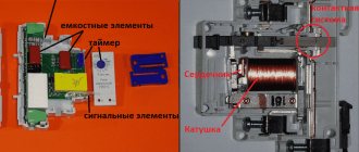
The design of a bimetallic thermal relay includes:
- Bimetallic plate
. It is made of two alloys with different coefficients of thermal expansion. Typically these are invar (low Kr) and chromium-nickel steel (higher Kr). They are welded or joined together by rolling. One of these metals heats up faster, the other slower. During current overload, part of the plate with high Kp bends towards the second part of the plate, which has lower Kp. This movement affects the group of contacts through the pusher. - Installation current regulator
. With its help, the maximum current value is set, above which the TR de-energizes the circuit. The actuation current is adjusted by increasing or decreasing the gap between the main plate and the pusher. - Electrical contacts
. They are connected to the windings of the magnetic starter of the thermal relay. Typically, a TP has two contacts - normally closed and normally open. When a bimetallic strip is subjected to force, the contacts change their position to the opposite.
The bimetallic strip is heated in one of two ways: directly due to the overload current or indirectly, through a separate heat-sensitive element. Both of these principles can be combined in one device, which significantly increases its efficiency. If the critical values of the consumer current are exceeded, the relay will open the circuit and de-energize the MP, and, consequently, the protected electrical equipment.
The operation of the relay element may be affected by increased ambient temperature. To compensate for this phenomenon and prevent false alarms, the TR design includes additional bimetallic plates that bend in the direction opposite to the spatial position of the main element.
Types of thermal relays
Manufacturers offer several types of TRs, which differ in design features and the type of MP used.
- TRP
. Single-pole switching device with a combined heating option. Used in DC networks in which the voltage does not exceed 400 V, to protect asynchronous motors. Resistant to shock and vibration loads. - RTL
. Protects electric motors from delayed starting, current asymmetry, overloads, and phase failure. - PTT
. Provides protection for asynchronous three-phase machines with short-circuit rotor from overloads, delayed start and phase imbalance. - TRN
. Used in DC power networks. Serve to control the start-up of electrical installations and the operating mode of the engine. - RTI
. Functions in conjunction with circuit breakers or fuses. - RTK
. Designed for use in automation circuits, it controls the temperature regime in the housing of electrical equipment.
The listed TPs do not protect electrical circuits from short circuits.
The difference between a magnetic starter and a contactor
Often, when selecting a switching device, confusion arises between magnetic starters (MF) and contactors. These devices, despite their similarity in many characteristics, are still different concepts. A magnetic starter combines a number of devices; they are connected in one control unit.
The MP may include several contactors, plus protective devices, special attachments, and control elements. All this is enclosed in a housing that has some degree of moisture and dust protection. These devices are mainly used to control the operation of asynchronous motors.
The maximum voltage with which the magnetic starter operates depends on the electromagnetic inductor. There are MFs of small ratings - 12, 24, 110 V, but most often they are used at 220 and 380 V
A contactor is a monoblock device with a set of functions provided for by a specific design. While starters are used in quite complex circuits, contactors are mainly found in simple circuits.
Thermal relay connection diagram
Connection of TP to power units is carried out in accordance with the manufacturer's instructions. In most cases, the TP is connected to the protected device through a normally closed contact, which is connected in series with the “stop” key. An open contact turns on thermal protection when the current exceeds the permissible values. Schemes for connecting a thermal relay to a motor circuit or other electrical equipment may be different, depending on the presence of additional devices.
Standard connection diagram for a thermal relay
The thermal relay is installed and connected together with a magnetic starter, which performs the functions of turning on the electric drive. There are options when the thermal relay is installed on a DIN rail or a separate panel.
When connecting a consumer to a 220 V or 380 V network, all phases after the magnetic starter are passed through a thermal relay, and then connected to the electric motor. When the start button is turned on, the power supply voltage enters the winding of the MP, which turns on the electric motor. If the load current increases to a value exceeding a critical value, the thermal relay is activated and turns off the electric motor.
The thermal relay TRN has only two incoming connections. In this case, the unconnected phase wire is run directly from the starter to the motor. Since the current in the electric motor varies proportionally, only two of them (any) can be controlled.
Summary
Diagrams that depict the principle of connecting a relay to a contactor may have other letter or digital designations. Most often, their decoding is given below, but the principle always remains the same. You can practice a little by assembling the entire circuit with a consumer in the form of a light bulb or a small motor. Using the test key, you can work out a non-standard situation. The start and stop keys will allow you to check the functionality of the entire circuit. In this case, it is necessary to take into account the type of starter and the normal state of its contacts. If there are any doubts, then it is better to consult an electrician who has experience in assembling such circuits.
{SOURCE}
Adjusting the thermal relay
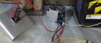
To effectively perform the function of shutting down an electric motor or other serviced device, it is necessary to correctly adjust the TP settings so that the likelihood of false alarms is eliminated. It is recommended to carry out the adjustment on a specialized stand using fictitious loads:
- Current is passed through the temperature sensing element to simulate a real thermal load.
- Using a timer, the response time is determined. When adjusting using a control screw at a current of 1.5 In, the response time should be no more than 2.5 minutes, 5-6 In - no more than 10 seconds.
Contact system on the contactor
Regardless of the standard size and manufacturer of electrical equipment, any three-phase contactor has a standard diagram of contacts and their connections. For ease of installation, all contacts are marked indicating their purpose. The marking is applied to the body of the device and looks like this:
- A1 (zero) and A2 (phase) – contacts for controlling the switching on and off of the contactor;
- Odd numbers 1, 3, 5 and markings L1, L2, L3 indicate the three-phase power input locations;
- Even numbers 2, 4, 6 and markings T1, T2, T3 indicate the connection points of the wires going to the current consumer;
- 13NO and 14NO are a pair of block contacts to provide the self-latching function.
Contact A2 is duplicated in the upper and lower parts of the device body for ease of switching. For the same purpose, the upper and lower (odd and even) group of power contacts can also be used to input or output power. When installing the contactor, you must be careful, otherwise the circuit will not work.
Incorrect phase connections must not be allowed. If you mix them up when installing the contactor, you will get reverse rotation of the motor. For this purpose, there are two ways of marking the insulation of cable cores - with numbers and color. The colors 1, 2 and 3 are yellow, green and red. The neutral conductor is white or marked with the number “0”. Connecting power contacts is not difficult. The main thing is the correct connection of the control voltage through the push-button station.
Marking of thermal relays
The labeling indicates most of the important characteristics of the TR. Example designation: RTL-Х1Х2Х3-Х4-Х5А-Х6А-Х7Х8, where
- RTL – type of thermal relay;
- X1 – rated current, 1 – up to 25 A, 2 – up to 100 A, 3 – up to 250 A, 4 – up to 510 A;
- X2 – 3 digits (conventionally), indicating the range of the current setting;
- X3 – letter characterizing the performance;
- X4 – return method: 1 – manual, 2 – self-return;
- X5 – Inom, A;
- X6 – current setting range, A;
- X7 – climatic version;
- X8 is a trademark.
A thermal relay is an effective element of protection for electric motors and other electrical equipment, which compares favorably with the input circuit breaker in that it is not subject to false alarms during short-term current surges.