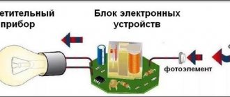
An ultrasonic sensor is a specialized instrument used for measurements in industrial automation. It can be used to measure distance, height and level, as well as determine position in space, detect the presence of objects and even count them individually. Due to this, the ultrasonic device is widely used in industry. However, there are some conditions that may prevent the device from performing the task correctly. More on all this later.
Operating principle
An ultrasonic rangefinder determines the distance to objects in the same way that dolphins or bats do. It generates sound pulses at 40 kHz and listens for echoes. Based on the time it takes for the sound wave to travel back and forth, you can unambiguously determine the distance to the object.
Unlike infrared rangefinders, ultrasonic rangefinder readings are not affected by light from the sun or the color of the object. But it may be difficult to judge the distance to furry or very thin objects. Therefore, it will be difficult to perform a high-tech mousetrap on it.
When sound is reflected from an obstacle, we hear an echo. The bat uses the reflection of ultrasonic waves to fly in the dark and to hunt insects. An echo sounder works on the same principle, which is used to measure the depth of water under the bottom of a ship or search for fish.
The principle of transmitting and receiving ultrasonic energy is the basis of many very popular ultrasonic speed sensors and detectors. Ultrasonic waves are mechanical acoustic waves whose frequency lies beyond the audibility of the human ear - more than 20 kHz. However, signals of these frequencies are perceived by some animals: dogs, cats, rodents and insects. And some species of mammals, such as bats and dolphins, communicate with each other using ultrasonic signals.
ULTRASONIC SENSOR Lego Mindstorm EV 3. SEE THE ROOT
Technical Specifications and Product Features:
- Distance measurement ranging from 1 to 250 cm
- Measurement accuracy up to +/- 1 cm
- The front illumination in the form of a red ring is constantly on when transmitting a signal and blinks when listening to the broadcast.
- If the ultrasonic signal is recognized, the sensor returns a logical value "True"
- Automatic identification is carried out by EV3 microcomputer software
Rice. 1 Ultrasonic sensor Lego Mindstorm EV 3 (cost including internal microcontroller and signal amplification chips $50, cost price $5)
Rice. 2 Lego Mindstorm EV 3 ultrasonic sensor circuit (ultrasonic sensor hardware schematics) is built on an STM8S103F3 microcontroller
- Introduction to stm8
- Microcontroller STM8S103F3
- LEGO MINDSTORMS EV3 central microcontroller circuit diagram programmable brick main hardware schematics
Rice. 3 Ultrasonic emitter AW8T40 and receiver AW8R40 ultrasonic sensor Lego Mindstorm EV 3
Description and purpose
An ultrasound sensor is a technical device that consists of several main parts:
Emitter
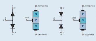
The most common types of emitters are magnetostrictive and piezoelectric.
Magnetostrictive - ultrasonic vibrations occur when the linear dimensions of a ferromagnet change in an alternating magnetic field.
Advantages:
- reliability - at least 10,000 hours of continuous operation;
- efficiency factor 80%.
Flaws:
- complex design;
- water cooling is required.
Piezoelectric - ultrasonic waves arise when the linear dimensions of a dielectric, made in the form of a membrane, change in an alternating electric field.
Advantages:
- simplicity of design;
- obtaining ultrasound of a wide frequency range;
- small sizes.
Flaws:
- low radiation power.
- Ultrasonic sensors mainly use piezoelectric emitters.
Receiver
The piezoelectric effect has a reverse side: ultrasound, hitting the piezoelectric element, causes oscillatory movements in it, as a result of which an electric current arises. Ultrasonic radiation sensors operate on this principle: the appearance of a current in the electrical circuit indicates the appearance of an object in front of the device.
Based on the design of the transceiver system, there are two types of sensors:
- with one head
In this circuit, the transmitter and receiver are a single element. The membrane, emitting ultrasound, receives the reflected signal and generates an electrical signal. This simplifies the design and reduces the size. However, there is a drawback. After radiation, the membrane cannot immediately switch to reception - it takes time for the vibrations to go out. This period was called “dead time”. The distance to the receiver, closer to which the signal reflected by the object will hit the membrane during dead time, is called the blind zone. At such a distance, the device does not detect a signal, and the object cannot be detected. They are fighting this phenomenon. Using settings and special operating modes, it is possible to reduce the blind spot by 2 times, but it is impossible to completely eliminate it.
- with two heads
The transmitter and receiver are separate parts of the structure. The device does not have a blind zone, however, it requires adjustment of the elements to match the frequency of signal transmission and reception.
The purpose of the ultrasonic sensor is to detect the appearance of objects in the coverage area, measure the distance to them, count objects moving in the viewing area, and determine the level of bulk cargo and liquids. When performing these tasks, it can work in the dark, in conditions of smoke, dust, high humidity, high and low temperatures. The device is insensitive to sound signals in the audible range. If necessary, it can be easily adjusted to other measuring ranges.
Ultrasonic sensor HC-SR04
Ultrasonic Sensor HC-SR04 – Ultrasonic Ranging Module HC – SR04 – Ultrasonic Sensor Distance Measuring Module – Sonar
Ultrasonic rangefinder HC SR04 is the most famous sensor for use in Arduino, Raspberry
Pi, ESP8266 and ESP32 modules.
Allows you to measure the distance to an object in the range from 2 to 400 (180) cm. For example, if you want to build a robot that avoids obstacles, then this rangefinder is perfect for your tasks.
The sensor has small dimensions and a simple interface. Rice. 4 Appearance of the ultrasonic sensor (sonar, ultrasonic sensor, ultrasonic module) HC-SR04
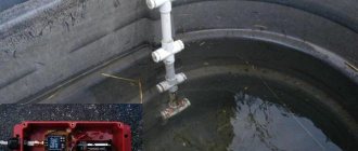
Ultrasonic level gauge operation
An ultrasonic level sensor is installed on the top of the tank and transmits an impulse downwards. This pulse, traveling at the speed of sound, is reflected back to the transmitter from the surface of the liquid. The transmitter measures the time delay between the transmitted and received echo signal, and the on-board processor of the device calculates the distance to the surface of the liquid.
An ultrasonic level sensor performs calculations to convert the wave's travel distance into a measure of the level in the tank. The time interval between the start of the sound queue and the receipt of the return echo is directly proportional to the distance between the sensor and the liquid in the vessel.
The frequency range of the ultrasonic level meter is in the range of 15–200 kHz. Low frequency instruments are used for more complex applications such as long distance and solid level measurements, while high frequency instruments are used for shorter distance liquid level measurements.
For the practical application of an ultrasonic level sensor, a number of factors must be taken into account.
Here are a few key points:
- The speed of sound through a medium (usually air) varies with temperature. The transmitter may have a temperature sensor to compensate for changes in operating temperature, which change the speed of sound and therefore the distance calculation that determines the accurate level measurement.
- The presence of foam/dust on the surface of the liquid can act as a sound-absorbing material. In some cases, the absorption may be sufficient to preclude the use of the ultrasonic method. To improve performance in applications where foam/dust or other factors affect wave travel to and from the liquid surface, some models may have a beam guide attached to the transducer.
- Extreme fluid turbulence can cause fluctuations in meter readings. Using an ultrasonic level sensor damping or response delay adjustment can help overcome this problem. The transceiver provides damping to control the maximum rate of change of the displayed material level and output signal fluctuation. Damping slows down the display's response speed, especially when liquid surfaces are in a state of agitation.
Names of terminals and ultrasonic emitters of the module
- Vcc is the positive power contact.
- Trig - digital input. To start the measurement, it is necessary to apply a pulse (logical unit) with a duration of 10 μs to this input. It is recommended to send the next pulse no earlier than 50 ms. which is related to the processing time of the first pulse.
- Echo - digital output. After processing the reflected signal, a pulse (logical unit) will be sent to this output, with a duration proportional to the distance to the object.
- GND - negative power contact (ground).
- The left ultrasonic emitter (marked with the letter T - transmiter) is an ultrasonic signal transmitter, the right ultrasonic emitter (marked with the letter R - receiver) is a receiver of the ultrasonic signal (echo) reflected from the object.
Mounting the sensor on an expansion board for Arduino
Where should I connect the sensor?
How to choose a place for it? Is there any free space on our expansion board at all? I’ll immediately make a reservation that the sensor can be mounted either on an expansion board or directly on the Arduino legs themselves. And now we’ll find out how to choose them. So. Let's take the diagram of our finished shield from here in the “schemes” section. This is what it looks like:
This is called a circuit diagram. It is fundamental because it basically shows what is connected to what, but this diagram does not reflect the actual location of the components on the board. But, in theory, it is easy and convenient to read. Initially I was uncomfortable, because... On the end of the Arduino, in fact, there is not a single leg, and in this diagram we see legs D2-D6 on it, which at first simply tore the pattern for me. But if you get used to it, that the scheme is so fundamental
, which simplifies everything to the state of “squares” and simply answers the question “what is connected to what” - then it becomes easier to work with it.
To read the symbols, you can use a short “dictionary”, but I recommend not doing this now, especially since our diagram reflects mostly finished components, and not board parts, each of which has its own symbol on the diagram. Now, don’t be alarmed, we will try to find a “place” in this diagram for only one new sensor. Please note that at the bottom of the diagram there are buttons:
There are three of them in the set, K1-K3. We already “stuck” them where needed when we assembled the radio according to the instructions. However, there are 2 more button sockets on the board: K4 and K5. They simply look like four holes, but they are marked differently. We are only interested in those pairs of holes that are marked on the board with a square contact.
Note to the hostess:
Why do the buttons have two contacts, and we use one each?
- The square pins lead to lines D5 and D6 of the Arduino. Round ones are “earth.”
- To connect the buttons, two contacts are needed, because When the button is pressed, the signal line (connected to the power supply through a resistor) and ground are closed.
- When connecting a sensor, ground is only needed for power. We will take the ground from the Arduino connector a little later, so in our case the second contacts will not be needed
.
This is how we will add a sensor to the circuit (Photoshop Mad Skills)
Assignment:
Look at the circuit diagram of the entire radio device again. How many and what legs does Arduino still have “free”? Can we hang something else on this Arduino within the framework of this device, in addition to our ultrasonic sensor? We are waiting for your answers in the comments.
Characteristics
- Supply voltage: 5V. Model HC-SR04 + operates in the range of 3.3V-5V (marked as HC-SR04 + on the back of the module board)
- Quiet mode consumption: 2 mA
- Operating consumption: 15 mA
- Maximum sensor polling rate: 20 Hz (50 ms polling period)
- Ultrasound frequency: 40KHz
- Viewing range: 2 cm - 4 m (1.8 m)
- Resolution (output signal gradation): 0.3 cm
- Effective viewing angle: 15°
- Working viewing angle: 30°
- weight - 8.28 grams
- Dimensions: 45*20*15 mm. LxWxD (W - excluding connection contacts)
Rice. 5 Dimensions of ultrasonic sensor HC-SR04
- Attention: ! It is not recommended to connect the module directly to the microcontroller board connected to the power supply, it is necessary to turn off the power supply when connecting the module, the GND pin of the module should be connected first, otherwise it may affect the normal operation of the module.
- ! When testing the module for measurement range and accuracy, the size of the area of the scanned object must be at least 0.5 square meters and its surface must be as hard and smooth as possible, otherwise it will affect the measurement results.
Rice. 6 Directional pattern of the ultrasonic sensor HC-SR04. Taken from the documentation for this sensor
Description of work:
Sensor viewing angle test, taken from the description on the website:
- https://life-prog.ru/view_msinv.php?id=62%D0%BC%D0%BE%D0%B6%D0%B5%D1%82
An ultrasonic distance sensor determines the distance to an object by measuring the time a sound wave is reflected from the object. The frequency of the sound wave is within the frequency of ultrasound, which ensures a concentrated direction of the sound wave, since sound with a high frequency is less dissipated in the environment. A typical ultrasonic distance sensor consists of two membranes, one of which generates the sound and the other of which registers the displayed echo. Figuratively speaking, we are dealing with a speaker and a microphone. The sound generator creates a small ultrasonic pulse with a certain period and starts the timer. Figure 3 – Ultrasonic distance sensor HC-SR04 The second membrane registers the arrival of the displayed pulse and stops the timer. From the timer time and the speed of sound it is possible to calculate the distance traveled by the sound wave. The object's distance is approximately half the distance traveled by the sound wave. Figure 4 - Operating principle of an ultrasonic distance sensor Limitations associated with the use of an ultrasonic distance sensor: 1. Partial reflections, or as they are called spurious echoes, can distort the measurement results (the reason may be surfaces that are curved or inclined relative to the direction of emission of the signal) . 2. Measuring objects made of sound-absorbing, insulating materials or having a fabric (wool) surface may lead to incorrect measurements due to signal absorption (attenuation). 3. The smaller the object, the less reflective surface it has. This results in a weaker reflected signal. 4. In high humidity (rain, snow), the signal may also be partially reflected from drops (snowflakes), which leads to a spurious echo signal.
The operating principle of the sensor is as follows: one of the piezoelements emits an ultrasonic wave when a pulse lasting 15 microseconds is applied, and the other piezoelement receives the same reflected wave from an obstacle. Then the delay time from transmission to reception of the wave is measured, then the distance is calculated and a signal is transmitted to the leg of the Echo sensor, with a duration proportional to the distance to the obstacle. All we have to do is send an impulse to the sensor, receive it and calculate the distance. Today we will learn how to work with HC-SR04 on BASCOM-AVR.
Let's set ourselves a task: to assemble a device that should measure the distance to any object using the HC-SR04 sensor and transmit data via UART to a PC.
For this purpose, you can use almost any AVR microcontroller, since the algorithm is very simple. I took Atmega8, and the result was the following circuit diagram of the device:
The description of the operating principle of the ultrasonic range finder HC - SR 04 can be divided into the following steps:
The next pulse can be emitted only after the echo from the previous one has disappeared. This time is called the cycle period. The recommended period between pulses should be at least 50 ms.
If a pulse with a duration of 10 μs is applied to the signal pin (Trig), the ultrasonic module will emit eight bursts of ultrasonic signal with a frequency of 40 kHz and detect their echo. The measured distance to the object is proportional to the width of the echo (Echo) and can be calculated using the formula shown in the graph above.
The sensor sends ultrasonic pulses and listens for echoes. We apply a high-level pulse with a duration of 10–15 microseconds to the Trig input of the sensor. The sensor sends out an ultrasonic "chirp" signal of eight short pulses at a frequency above the limit of human hearing range. The sensor electronics know the speed of sound in air. By measuring the time between sent and received ultrasound, the HC-SR04 ultrasonic sensor generates an output signal. This principle of echolocation is used by dolphins and bats. After about a microsecond, the HC-SR04 ultrasonic sensor outputs a high-level pulse at the Echo output for up to 38 milliseconds. If no obstacles are detected, the output will be a signal with a duration of 38 ms. Thus, to operate the sensor, the device electronics require one digital control output and one input for the sensor signal. The pulse length at the Echo output is proportional to the distance to the obstacle. The distance is calculated by the formula: S=F/58, where S is the distance in centimeters, F is the pulse duration in microseconds. There is an Ultrasonic software library for interaction between Arduino and the sensor.
Step 1: A pulse lasting 10 microseconds is applied Trig input For the rangefinder, this is a command to start measuring the distance in front of it.
Step 2: The device generates 8 ultrasonic pulses with a frequency of 40 kHz through the output sensor T.
Step 3: The sound wave is reflected from the obstacle and hits the receiving sensor R.
Step 4: Echo output , the duration of which is directly proportional to the measured distance.
Step 5: On the side of the control controller, we convert the duration of the Echo into distance using the formula: pulse width (μs) / 58 = distance (cm) .
The figure below shows timing diagrams that clearly explain the steps listed.
Short pulses with a duration of 10 μs must be applied to the Trig signal. This pulse triggers the echo locator. It already generates a packet of ultrasonic pulses (40 kHz) for the emitter and itself catches the reflected echo. Based on the time the sound travels back and forth, the sensor determines the distance. For us, the sensor itself gives an impulse to the Echo contact with a duration proportional to the distance. Echo signal duration is from 150µs to 25ms. If there is no answer, then the Echo duration is about 40ms. The distance to the object can be calculated by dividing the duration in microseconds of the echo by 58. The distance in centimeters is obtained. The maximum distance that can be measured according to the documentation is 5 meters. The recommended sensor polling period is 50-10ms. The sensor's radiation pattern is not very sharp - about thirty degrees.
- The operation of the ultrasonic rangefinder HC-SR04 is based on the principle of echolocation. It emits sound pulses into space and receives a signal reflected from an obstacle. The distance to the object is determined by the time of propagation of the sound wave to the obstacle and back. The sound wave is triggered by applying a positive pulse lasting at least 10 microseconds to the TRIG leg of the rangefinder. As soon as the pulse ends, the rangefinder emits a packet of sound pulses with a frequency of 40 kHz into the space in front of it. At the same time, the algorithm for determining the delay time of the reflected signal is launched, and a logical unit appears on the ECHO rangefinder leg. As soon as the sensor detects the reflected signal, a logical zero appears at the ECHO pin. The duration of this signal (“Echo Delay” in the figure) determines the distance to the object. The distance measurement range of the HC-SR04 rangefinder is up to 4 meters with a resolution of 0.3 cm. The viewing angle is 30 degrees, the effective angle is 15 degrees. Current consumption in standby mode is 2 mA, during operation - 15 mA.
- The sound wave is triggered by applying a positive pulse lasting at least 10 microseconds to the TRIG leg of the rangefinder. As soon as the pulse ends, the rangefinder emits a packet of sound pulses with a frequency of 40 kHz into the space in front of it. At the same time, the algorithm for determining the delay time of the reflected signal is launched, and a logical unit appears on the ECHO rangefinder leg. As soon as the sensor detects the reflected signal, a logical zero appears at the ECHO pin. The duration of this signal (“Echo Delay” in the figure) determines the distance to the object. The distance measurement range of the HC-SR04 rangefinder is up to 4 meters with a resolution of 0.3 cm. The viewing angle is 30 degrees, the effective angle is 15 degrees. Current consumption in standby mode is 2 mA, during operation - 15 mA.
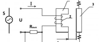
Rice. 40. Piezoelectric ultrasonic transducer: A - input voltage causes the element to bend, which causes the generation of ultrasonic waves. Conversely, as a result of the influence of waves, voltage appears at the output of the converter; B - ultrasonic transducer with an open aperture for working in air
- More details: https://www.kakprosto.ru/kak-918792-kak-podklyuchit-ultrazvukovoy-dalnomer-hc-sr04-k-arduino#ixzz4PeP45Mxx
- Contacts, in order from left to right, from the front side:
- Vcc – 5V power supply
- Echo - exit
- Gnd – ground
Trig – input
Work process:
- We connect the sensor to power and to the control device
- We send a signal with a duration of 10 μs to the rangefinder input (Trig) (or a little more, it triggers at 10 μs)
- The sensor speaker emits 8 signals at 40 kHz, and the microphone receives their echo (or does not receive it)
- The sensor sends a signal to its output (Echo) with a duration corresponding to the distance to the obstacle: 150 μs (at 2 cm to the obstacle) – 25 ms (at 4 m to the obstacle) and 38 ms in the absence of an obstacle. Note: sound travels a distance of 4 cm (2 cm from the speaker to the obstacle and 2 cm back to the microphone) in 0.04 m / 335 m/s = 0.000119 s = 119 μs and 8 m in 8 m / 335 m/s = 0.023881 s = 23.881 ms.
What time passes from the sensor being triggered by an input signal to the beginning of point 3 and from the beginning of point 3 to the beginning of point 4 is not stated anywhere - this will soon be found out by me experimentally.
To calculate the distance to an obstacle, the following formulas are used:
- Output pulse length in microseconds / 58 = distance in centimeters
- Output pulse length in microseconds / 148 = distance in inches
The HC-SR04 module circuit has 2 converters of ultrasonic signals into low-power electrical signals, one TCT40-16T - ( T - Transmiter in the diagram is designated as Emit MK2, see diagram) is designed for transmitting (emission) ultrasonic waves into the surrounding space and the second TCT40-16R ( R - Receive in the diagram is designated as Receive MK1, see diagram) for receiving reflected ultrasonic waves from objects in the surrounding world.
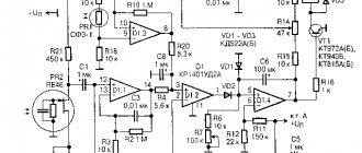
Relatively high voltage is required to transmit ultrasonic waves. MAX232 microcircuit (designation on the board is U3, see diagram) amplifies the 5 volt input supply voltage to +/- 9-10 volts. MAX232 microcircuit is connected between two outputs (T OUT1 - pin 14 and T OUT2 pin 7, see diagram), so that in fact the amplitude of the voltage value of the pulses supplied to the ultrasonic transmitter reaches up to 20 volts. MAX232 microcircuit through transistor Q2 (in the new circuit it is absent and power is supplied directly to input 16 of the microcircuit and in this case the microcontroller does not turn off) for some time before and during pulse emission, since internal charge switching creates excess noise on the receiving side module. When the module goes into receive mode on the MAX232 chip, power is turned off at output 10 - Signal of the EM78P153S microcontroller (EM78P153S Chinese microcontroller operates at a frequency < 27 MHz.
the TCT40-16R ultrasonic signal converter is carried out by the LM324 microcircuit (designation on the board - U1, see diagram), which contains 4 operational amplifiers. Operational amplifier U2D (see diagram) amplifies the signal 6 times. Operational amplifier U2C has feedback (1st order) and is a bandpass filter, then operational amplifier U2B amplifies the input signal 8 more times. The last operational amplifier U2A is used together with Q1 as a hysteresis comparator where the rectangular pulses and the analog input signal are separated. I simulated the filter in PSpice and it is not centered at 40KHz as it should be but instead it has a peak at 18kHz. By changing only two resistors (R13 to 2K2 and R11 to 18K), the filter response is shifted to the pulse frequency, and this significantly increases detection sensitivity.
MICROCONTROLLER ESP-8266 AND ULTRASONIC SENSOR HC-SR04
Redesign of ultrasonic sensor HC-SR04
Rice. 4 Ultrasonic emitter/receiver TCT40-16R/T (cost including internal microcontroller and signal amplification chips < $1)
Rice. 5 Spatial radiation diagram of the ultrasonic emitter/receiver TCT40-16R/T (if we saw ultrasound, then we would see the propagation of ultrasonic waves in space)
Characteristics of ultrasonic emitter/receiver TCT40-16R/T
1. Model: TCT40-16R/T (16mm in diameter) 2. Nominal frequency (KHz): 40KHz 3. Sound pressure emission At10v (dB=0.02mPa): ≥ 117dB 4. Receiver sensitivity at40KHz (dB=V/ ubar): ≥-65dB 5. Electrostatic potential at1KHz, <1V (PF): 2000±30%
Ultrasonic transducers reference 1
Ultrasonic transducers help 2
APPLICATION
Echo sounder. Category “How does it work?”
Murata Ultrasonic Sensors
Sensors designed for parking machines have high sensitivity: with a resonant frequency of 40 kHz. The sensor range reaches 1.5 meters with a resolution of 9 mm. Sensors are available with different radiation patterns, both symmetrical (circular) and asymmetrical (oval).
Other Applications
Ultrasonic sensors are used in various fields:
- To control the physical and chemical characteristics of substances. The principle of operation is based on comparing the speed of sound in the substance being tested with the reference one - a discrepancy indicates changes in the substance.
- To control the flow of liquid substances in pipelines. The principle of operation is based on comparing the speed of ultrasonic vibrations in the direction of flow and against it. The method does not require placing the sensor inside the pipeline - the sensor is attached from the outside.
- To determine levels of liquid or bulk materials. The principle of operation is based on the reflection of ultrasound sent by the sensor from the interface between gas and liquid or bulk material. When the level decreases, the time it takes for the oscillations to pass through changes, and the device signals this.
- For the security of premises. There are several operating principles:
- The security sensor emits ultrasonic radiation. When an object appears in the detection zone, the reflected signal is received by the sensor. Then it acts according to the selected algorithm: turns on the siren, sends a signal to the security panel, etc.;
- The signal from the security sensor reaches a receiver located at some distance. When an object passes between the receiver and the emitter, the signal is interrupted, and the sensor operates according to the given algorithm.
For reliability, several ultrasonic security sensors are usually used, operating on different principles.
- Fire safety. An ultrasonic fire detector operates on the same principle as a security alarm. It reacts not to an object, but to the movement of air heated by fire. It is highly sensitive. Gas temperature meters and fire alarms based on changes in the speed of propagation when the temperature of the environment changes or the appearance of smoke.
Ultrasonic quality control of materials and products. The principle of operation is based on the difference in the speed of sound in different media and the reflection of ultrasound from the boundary of the media. Detects the exact location of internal defects at a depth of several meters.
- Medicine. Carrying out ultrasound examination to diagnose internal pathologies. The principle of operation of the sensor is based on the speed of passage of ultrasonic waves in human tissue. The reflected signal changes wavelength in different tissues of the body. Visualization of the signal on the device screen makes it possible to see the structure of the internal organs of a person.
Connecting to Arduino
If you plan to use the HC-SR04 ultrasonic rangefinder with Arduino you can use the existing libraries:
- Ultrasonic is the most popular library for the HC-SR04.
- NewPing is more accurate and faster.
- Ultrasonic rangefinder URM37
Pinout:
- Vcc - positive power supply
- TRIG - TRIG input
- ECHO - ECHO output
- GND - power zero
The power pins are supplied with a constant voltage of 5 V, the current consumption in operating mode is about 15 mA.
The TRIG input connects to any pin of the microcontroller. A pulse digital signal with a duration of 10 μs must be supplied to this pin. Based on the signal at the TRIG input, the sensor sends ultrasonic pulses.
After receiving the reflected signal, the sensor generates a pulse signal at the ECHO pin, the duration of which is proportional to the distance to the obstacle.
The sensor pins can be connected to a breadboard or Arduino female-male wires. And with Troyka Shield through female-to-female wires.
- Garage parking sensor
This rangefinder can serve as an excellent sensor for a robot, thanks to which it can determine distances to objects, avoid obstacles, or build a map of the room. It can also be used as a sensor for alarms that are triggered when objects approach.
Application of ultrasonic radiation sensors in robotics
The main task solved in robotics using sensors of this type is to orient the robot on the ground, avoid collisions and avoid obstacles.
Advantages of orientation systems built on ultrasonic sensors:
- price;
- easy to manufacture, as it is assembled from easily accessible elements;
- when integrated into robotic devices, there is no need to change the robot control circuit;
- versatility;
- insensitivity to adverse environmental factors: smoke, dust, lack of light, high humidity.
Considering the short range of action of sensors in the air, they are used in spaces of limited volume of artificial or natural origin, with hard and smooth surfaces. This ensures a stable echo signal is obtained. In such conditions, the information from the ultrasonic rangefinder is objective. For all-round visibility, an increase in the number of sensors is necessary. Determining the distance to an obstacle in motion, stopping and detour is achieved by software.
Ultrasonic sensor systems are widely used in underwater robots, being the main means of monitoring the surrounding space. Here, magnetostrictive emitters with high acoustic power are used as hydroacoustic transducers.
Specifications
https://www.yourmestudio.com/rcw-0002-ultrasonic-ranging-module-p717.html
- Supply voltage: 5 V
- Quiet mode consumption: 2 mA
- Operating consumption: 15 mA
- Distance range: 2–400 cm
- Effective viewing angle: 15°
- Working viewing angle: 30°
Product Description:
TK T 40-16 t/r 1
- (Tc): piezoceramics Ultrasonic sensor
- (T): Category t-generality
- (40): Center frequency (kHz)
- (16): outer diameter? (mm)
- (T): use mode: emitter; r-receiver; TR-compatible emitter and receiver
- (1): ID - 1,2, 3...
Circuit testing
- 1 Sine Wave Generator 1 Swept Signal Generator
- 2 cymometer 2 Frequency meter
- 3 standard speakers 3 voltmeter
- 4 Get sensor model 4 emit sensor model
- 5 oscilloscope 5 Standard microphone
- 6 audio frequency characteristics Instrument display
Product performance 1). Rated Frequency (KHz): 40KHz 2). emit sound pressureat10V(=0.02Mpa):? 117dB 3). Reception Receiver sensitivity at40KHz (dB = v/ubar):?-65dB 4). Electrostatic potential at1KHz, <1V (PF): 2000 +/-30% 5). Detection range (m): 0.2~20 6).-6dB direction angle: 80o 7). Sheathing material: aluminum 8). Trim COLOR: silver
Literature
- Object detecting system of reflection type. US Patent 4,542,489. Publ. Sept 17, 1985 (Naruse, Aisin Seiki Kabushiki Kaisha)
- Ultrasonic transducer. US Patent 4,636,997. Publ. Jan 13, 1987 (Toyama, et al., Nippon Soken, Inc.)
- Ultrasonic transducer. US Patent 4,433,398. Publ. Feb 21, 1984 (Kodera, et al., Nippon Soken, Inc.)
- Ultrasonic transducer. US Patent 4,754,440. Publ. June 28, 1988 (Naruse, Aisin Seiki Kabushikikaisha)
- Piezoelectric transducer for transmitting or receiving ultrasonic waves. US Patent 4,755,975. Publ. July 5, 1988 (Ito, et al., NGK Spark Plug Co., Ltd.)
- Ultrasonic distance sensor. US Patent 4,918,672. Publ. April 17, 1990 (Iwabuchi, et al., Niles Parts Co., Ltd.)
- Ultrasonic obstacle sensor. US Patent 5,076,384. Publ. Dec 31, 1991 (Wada, et al., Mitsubishi Denki Kabushiki Kaisha)
- Method and device for ultrasonic distance measuring. US Patent 5,508,974. Publ. April 16, 1996 (Meyer, et al., Robert Bosch GmbH)
- Method and device for operating an ultrasonic sensor. US Patent 5,531,118. Publ. July 2, 1996 (Knoll, et al., Robert Bosch GmbH)
- Ultrasonic sensor. US Patent 5,869,764. Publ. Feb 9, 1999. (Schulte, Microsonic Gesellschaft fur Mikroelektronik und Ultraschalltechnik mbH)
- Apparatus for distance measurement by means of ultrasound. US Patent 6,166,995. Publ. Dec 26, 2000 (Hoenes, Robert Bosch GmbH)
- Ultrasonic sensor. US Patent 6,250,162. Publ. June 26, 2001. (Amaike, et al., Murata Manufacturing Co., Ltd.)
- Ultrasound sensor for distance measurement. US Patent 6,181,645. Publ. Jan 30, 2001. (Li)
- Ultrasound sensor for distance measurement. US Patent 6,370,086. Publ. April 9, 2002. (Li)
- Ultrasonic sensor and obstruction detector having accurate obstruction detection capabilities. US Patent 6,085,592. Publ. July 11, 2000. (Kawashima, Denso Corporation)
- Overpaintable bumper with ultrasound transducer. US Patent 6,039,367. Publ. March 21, 2000 (Muller, et al., ITT Manufacturing Enterprises, Inc.)
- Ultrasonic transducer. US Patent 6,374,676. Publ. April 23, 2002 (Arnold, et al., Robert Bosch GmbH)
- Ultrasonic transducer. US Patent 6,465,935. Publ. Oct 15, 2002 (Wannke, et al., Robert Bosch GmbH)
- Ultrasonic transceiver and vehicle's surrounding obstruction sensor. US Patent 6,484,581. Publ. Nov 26, 2002 (Nishimoto, et al., Mitsubishi Denki Kabushiki Kaisha)
- Ultrasonic sensor system and method having input capture for echo processing. US Patent 6,338,028. Publ. Jan 8, 2002 (Shelton, et al., TRW Inc.)
- Ultrasound sensor. US Patent 6,520,019. Publ. Feb 18, 2003 (Schon, et al., TRW Automotive Electronics & Components GmbH & Co. KG)
- Ultrasound sensor. US Patent 6,532,193. Publ. March 11, 2003 (Fehse, et al., Robert Bosch GmbH)
- Ultrasonic sensor. US Patent 6,792,810. Publ. Sept 21, 2004 (Kupfernagel, et al., Valeo Schalter und Sensoren GmbH)
- Ultrasonic sensor assembly for a vehicle reversing radar. US Patent 6,909,670. Publ. June 21, 2005 (Li)
- Ultrasonic sensor. US Patent 7,004,031. Publ. Feb 28, 2006 (Oda, et al., Denso Corporation, Nippon Soken, Inc.)
- Choosing an Ultrasonic Sensor for Proximity or Distance Measurement. Donald P. Massa, Massa Products Corp. Parts 1 & 2, Sensors, Feb - March 1999
- Ultrasonic Sensing for Challenging Environments. Kassan J., Morelli J. Pepperl+Fuchs Inc. Sensors, July 2005
Useful resources:
Ultrasonic rangefinder HC-SR04 connection to Arduino
Ultrasonic sensor HC-SR04 – rangefinder on a microcontroller
https://www.elecfreaks.com/store/download/product/Sensor/HC-SR04/HC-SR04_Ultrasonic_Module_User_Guide.pdf
https://robocraft.ru/blog/arduino/770.html
Ultrasonic Distance Sensor HC-SR04
Pengetahuan Dasar Timer Untuk Pengukuran Jarak Dengan Ultrasonic
Triggering a Servo Using HC-SR04 Distance Sensor and Arduino
https://robocraft.ru/blog/electronics/772.html
Raspi-sump October 2014 Embedded Release LinuxJournal
https://www.arduino.cc/en/Tutorial/Ping
Simple ultrasonic range finder using HC-SR04
Obstacle Sensor using Arduino and HCSR04
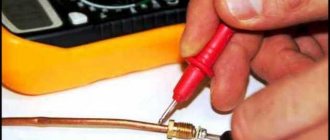
How to Test DYP-ME007 Ultrasonic Rangefinder Using NE555 and Multimeter
https://macduino.blogspot.ru/2013/11/HC-SR04-part1.html
https://amperka.ru/product/ultrasonic-urm37
https://image.dfrobot.com/image/data/SEN0002/URM04V2.0Mannual1.1.pdf
https://people.ece.cornell.edu/land/courses/ece4760/FinalProjects/s2012/xz227_gm348/xz227_gm348/URM3.2_Mannual_Rev2.pdf
RCW-0012 Ultrasonic Module Distance Measuring Transducer Test Indication Module
https://www.farnell.com/datasheets/81163.pdf?_ga=1.169892256.1853603956.1478607467
https://chinaultrasound.en.alibaba.com/product/60268805778-800581237/40Khz_TCT40_16R_T_Air_Ultrasonic_Ceramic_Transducer_Ultrasonic_Sensor.html
Brief conclusions
Ultrasonic distance sensors are versatile and accurate enough to be used for most hobbyist projects. The article discusses the extremely popular HC SR04 sensor, which easily connects to the Arduino board (for this you should immediately provide two free pins, but there is a connection option with one pin). There are several free libraries for working with the sensor (only one of them, NewPing, is discussed in the article), but you can do without them - the algorithm for interacting with the internal controller of the sensor is quite simple, we showed it in this article.
Based on my own experience, the HC-SR04 sensor is accurate to within one centimeter at distances from 10 cm to 2 m. At shorter and longer distances, strong interference may occur, which is highly dependent on surrounding objects and method of use. But for the most part, the HC-SR04 did a great job.
Main types of ultrasound sensors:
- Convex sensor
- Microconvex sensor
- Linear sensor
- Sector sensor
- Phased sector sensor
- Intracavitary sensor (transrectal/anal, transvaginal, transurethral)
- Biplane sensor
- 3D/4D (Live-3D) sensor
- Matrix volumetric sensor
- Pencil Doppler Probe
- Transesophageal TEE sensor
- Video endoscopic sensor
- Biopsy probes
- Catheter (intraoperative) sensor
- Intravascular sensor
- Laparoscopic sensors
- Monocrystal sensors
- Mechanical sensors
- Ophthalmic sensors
- Transcranial sensor
- Otolaryngological sensors
- Veterinary sensors
- Planar sensors
Operation of linear, convex and sector sensors
In linear and convex sensors, piezocrystals emit in groups alternately until all the crystals from the beginning of the piezocrystal matrix to the end are used up. One frame on the display will be updated when all groups send and receive the ultrasonic signal in turn.
In sector phased sensors, all crystals emit almost simultaneously. Small electronic signal delays are specially introduced onto each crystal in order to direct the scanning beam. The image on the display will be updated when the beam scans the entire viewing sector.