It is impossible to imagine modern civilization without electricity. A huge part of hydrocarbons is used to generate electricity.
However, electricity cannot be transported like oil or coal. For its transportation, power transmission lines (PTLs) are used, providing high-power electricity traffic over the required distances. Bringing the parameters of the energy transmitted through them to the standards characteristic of its consumers implies the use of transformer substations that provide the necessary voltage in the network. Thus, all electrical installations are powered, from a light bulb in a room to industrial equipment.
To prevent injuries to service personnel and, especially, deaths, given the high voltage, grounding devices for overhead lines and substations are used. This publication aims to understand the reasons for their need, as well as the designs of these devices.
Why do you need to ground power lines and substations?
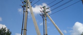
By and large, an overhead line (OHL) is a series of pillars (supports) exposed to natural factors such as temperature changes, precipitation, direct exposure to solar ultraviolet radiation, and others. Due to their influence, the properties of dielectrics may change and direct contact of the current-carrying parts of the cable with the support may occur. Among other things, there are often short-term voltage surges in the line that significantly exceed the nominal (permissible) value, which can lead to a short circuit between the cable and the structural elements of the support.
If you touch such a pole, a person can be injured and even die. Therefore, installing grounding on an overhead line does not at all belong to the category of recommendations or whims of control authorities. This is dictated by the Electrical Installation Rules (ELR) as the main regulatory document regulating the requirements for power systems, including overhead lines. According to this document, grounding devices for overhead line supports are mandatory.
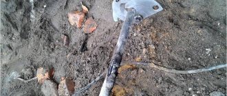
The issue of lightning protection of structures stands apart. The supports can be made of wood, reinforced concrete or steel. For supports standing in an open field, sometimes having a very significant height, being struck by lightning is by no means a rare occurrence. If for steel or reinforced concrete, which have good electrical conductivity and are incapable of combustion, this will not cause serious damage, then for a wooden structure it is fraught with destruction or ignition. Considering the colossal voltage of a lightning discharge, it is possible to destroy the dielectrics that protect structural elements from the current-carrying parts of the overhead line, which, in turn, leads to an accident.
All this applies equally to substations. Until now, some of them are a large transformer in the middle of a field, powering a farm, for example. Transformer installations are subject to all the negative influences as overhead lines. Even if this is not the case, they must comply with the requirements of the PUE.
A mast or substation equipped with a grounding device behaves differently. All the charge that hits the support will flow to the ground, given its low resistance and huge capacity. This means that the structure will not be energized and will be safe for human life and health.
How should metal outdoor lighting poles be grounded?
Many people have a question: “Do I need to ground metal lighting poles?”
According to electrical safety standards, instructions for lightning protection and the installation of grounding networks, all steel supports used for the installation of outdoor lighting systems must be grounded.
PUE clause 6.1.45. When performing protective grounding of outdoor lighting fixtures, reinforced concrete and metal supports, as well as cables, must also be connected to the ground electrode in networks with an insulated neutral and to the PE (PEN) conductor in networks with a grounded neutral.
The operating principle of protective grounding is that in the event of an insulation failure, electric current flows to the ground. Thus, voltages that are not dangerous to humans are distributed in the spreading zone, depending on the resistivity of the soil and the location of the ground electrode. If street lighting is installed in networks with an insulated neutral, the pins or hooks of phase wires on iron supports, as well as fittings and any metal structures must be grounded using special devices - a grounding loop consisting directly of grounding conductors and grounding conductors. Foundations for supports are not grounding conductors, because covered with special anti-corrosion mastic that has dielectric properties.
How to ground a lighting pole?
Grounding electrodes are special elements that are installed in the ground and can be in the form of rods - metal rods, or in the form of steel strips (see drawing of the grounding of a lighting support with a triangular grounding loop). Vertical rods are driven to a depth of up to 3 meters, and their upper part of the ground electrode should be installed approximately half a meter from the base of the soil. The horizontal grounding conductors, which are most often used on rocky soils, are also located at the same depth. When installing grounding conductors, the conductors used to connect the grounding loop must have a diameter of at least 6 mm. The grounding conductors and grounding conductors are connected to each other by field welding, and the joints are painted. If outdoor lighting is installed in networks with a grounded neutral, the pins and hooks of phase wires on metal supports, as well as fittings and any metal structures must be connected to the neutral working wire. As a rule, this is done using a special bolt welded directly to the support or eye. Thus, grounding of metal poles of street lighting with cable power is carried out: • In networks with an isolated neutral through the use of a metal cable sheath; • In networks with a grounded neutral through the neutral core, which is connected to the cable sheath. To monitor the grounding of street lighting poles, after all electrical installation work has been carried out, the resistance of the grounding device should be measured using a special device. The resistance value should not be higher than 50 ohms. Grounding lighting poles can serve as lightning protection
This is especially important when the street lighting support is installed away from buildings in open areas. Due to their structural dimensions, that is, a significant elevation above the ground, lighting poles are exposed to greater exposure to various types of weather phenomena than other components of the landscape; the height of the support can reach from 3 to 11 meters, due to which it is one of the first to absorb the electric discharge
This is especially true for places that are particularly susceptible to discharge. Indeed, if lightning strikes a support without grounding, overvoltage can occur throughout the network as a whole, which can lead to serious consequences.
For example, let’s imagine a situation: lightning still struck a lighting support (regardless of whether there was a lightning rod there or not). Where will the lightning current go? If there is no connection with the ground at all, then the entire lightning impulse will go into the electrical network. Conclusion: it is necessary to ground the supports (and preferably each one) at least to drain the lightning current; in the substation from which street lighting is supplied, it is necessary to provide good protection against overvoltage secondary manifestations of lightning.
Primary requirements
According to the requirements of the PUE, almost every support must have a grounding device. It is necessary to prevent atmospheric overvoltage (lightning), protect electrical equipment located on the mast, and also implement re-grounding. Its resistance should not exceed 30 Ohms. Moreover, lightning rods and similar devices must be connected to the ground electrode by a separate conductor. Among other things, guy wires installed for support stability, if they are present in its design, must be grounded. It is preferable to weld all interconnections, reduction wires and grounding wires, for example, and, if not possible, bolt them together . All parts of the grounding device must be made of steel with a diameter of at least 6 mm. The conductor itself and the joints must have an anti-corrosion coating. Usually this is galvanized steel wire of the appropriate diameter.
Reinforced concrete pillars
The grounding device for overhead lines depends on the material of the supports. In the case of a reinforced concrete structure, all reinforcement elements protruding from above and below must be connected to a PEN conductor (zero bus), which subsequently plays the role of grounding. Hooks, brackets and other metal structures located on the support should also be attached to it. All this equally applies to metal overhead line masts.
Wooden pillars
With wooden overhead line supports, the situation is somewhat different. Due to the dielectric properties of wood, each of the masts does not require a separate grounding device. It is installed only if there is a lightning rod or re-grounding on the mast. In addition, the metal sheath of the cable is connected to the PEN bus of the line at the points where the overhead line transitions into the cable line.
Low-rise buildings
All types of supports must be equipped with grounding devices, if we are talking about settlements with low-rise buildings (1 or 2 floors).
The distance between such masts depends on the average annual hours at which thunderstorms occur. If this value does not exceed 40, then the gaps between supports with lightning rods should be less than 200 m. Otherwise, this distance is reduced to 100 m. In addition, supports representing branching from overhead lines to objects with potentially large crowds of people, clubs or a cultural center, for example.
Installation of ground electrodes
Grounding of overhead lines is carried out by vertical or horizontal ground electrodes. In the first case, these are steel pins buried or driven into the ground, and in the second, they are strips of metal located parallel to the ground below its surface. The latter option is used for soil with high resistivity. After burying the circuit, the earth is compacted to ensure better contact with the metal. Then the resistance at the grounding of the overhead line supports is measured. It is the product of the value obtained by direct measurement by a coefficient depending on the type and size of the ground electrode, as well as the climatic zone (there are special tables).
Reinforced concrete structures
For overhead lines with voltages from 6 to 10 kV, the role of grounding descents is played by the pole reinforcement. If you have guys, you can use them too. The routes being laid are made from conductors with a cross-section of 35 square meters or more. mm or a rod with a diameter of at least 10 mm. During operation, it is necessary to regularly check the condition of the descent: its damage can not only lead to electric shock to people and partially destroy the support itself if the insulation of the wiring is broken.
When arranging the grounding of reinforced concrete supports, it is necessary to take into account the soil resistance. If it does not exceed 100 ohms/meter, the pole-tied system should read no more than 30 ohms. In more dielectric dry soil, which is a poor conductor of current, it is 0.3 Ohm. In the first case, it is allowed to use one lower grounding pin electrode 200 cm long, which comes directly with the reinforced concrete pole. But the resistance of the ground electrode also depends on its design, the depth of arrangement and the relative position, if there are several elements. A specialized specialist can say more precisely here.
Features of substations
Everything previously described also applies to substations, despite the fact that they are under the roof. The only exception is that people are there quite often or constantly, and, therefore, special requirements are imposed on their grounding.
In general, substation grounding consists of the following elements:
- inner circuit;
- outer contour;
- facility lightning protection device.
The internal grounding loop of the substation provides a simple and reliable connection to the ground of all devices located inside the substation. To do this, a steel strip is secured with dowels along the perimeter of all premises of the facility at a height of 40 cm from the floor. The contours of all premises, as well as their component parts, are connected by welding or threaded connections, if provided. All metal parts not intended for the passage of current (instrument housings, fences, hatches, etc.) are connected to this bus. Such strips are equipped with threaded connections with increased width washers and wing nuts. This allows you to obtain reliable portable grounding. The zero bus of the power transformer, taking into account the circuit with a solidly grounded neutral, is connected to the resulting circuit.
What does grounding consist of?
- External ground loop. It is located outside the premises, directly in the ground. It is a spatial structure of electrodes (grounding conductors) connected to each other by an inseparable conductor.
- Internal ground loop. A conductive bus located inside a building. Covers the perimeter of each room. All electrical installations are connected to this device. Instead of an internal circuit, a grounding shield can be installed.
- Grounding conductors. Connecting lines designed to connect electrical installations directly to the ground electrode, or internal ground loop.
Take a closer look at these components.
External or outer contour
The installation of the ground loop depends on external conditions. Before starting the calculation and completing the design drawing, you need to know the parameters of the soil in which the ground electrodes will be installed. If you have built a house yourself, these characteristics are known. Otherwise, it is better to call surveyors to obtain an opinion on the soil.
What types of soils are there, and how do they affect the quality of grounding? Approximate resistivity of each soil type. The lower it is, the better the conductivity.
- Plastic clay, peat = 20–30 Ωm m
- Plastic loam, ash soils, ash, classic garden soil = 30–40 Ohm m
- Chernozem, shales, semi-hard clay = 50–60 Ohm m
This is the best environment to install an external ground loop. The current flow resistance will be quite low even with low moisture content. And in these soils the natural humidity is usually above average.
Semi-solid loam, mixture of clay and sand, wet sandy loam - 100–150 Ohm m
The resistance is slightly higher, but at normal humidity the grounding parameters will not exceed the standards. If there is prolonged dry weather in the installation region, it is necessary to take measures to forcibly moisten the installation sites of ground electrodes.
Clay gravel, sandy loam, wet (constant) sand = 300–500 Ohm m
Gravel, rock, dry sand - even with high general humidity, grounding in such soil will be ineffective. To comply with standards, deep grounding will have to be installed.
Many facility owners, saving on matches, simply do not understand why a grounding loop is needed. Its task, when connecting a phase to the ground, is to ensure the maximum value of the short circuit current. Only in this case will the protective shutdown devices operate quickly. This cannot be achieved if the current flow resistance is high.
Having decided on the soil, you can choose the type, and most importantly, the size of the ground electrodes. Preliminary calculation of parameters can be performed using the formula:
The calculation is given for vertically installed grounding conductors.
Decoding the formula values:
- R0 is the resistance of one ground electrode (electrode) obtained after calculation in ohms.
- Rekv - soil resistivity, see information above.
- L is the total length of each electrode in the circuit.
- d is the diameter of the electrode (if the cross-section is circular).
- T is the calculated distance from the center of the electrode to the surface of the earth.
By setting known data, as well as changing the ratio of values, you should achieve a value for one electrode of the order of 30 Ohms.
If the installation of vertical grounding electrodes is not possible (due to the quality of the soil), the resistance value of horizontal grounding electrodes can be calculated.
Therefore, it is better to spend more time driving vertical rods than to monitor the barometer and air humidity.
And yet we present the formula for calculating horizontal grounding conductors.
Accordingly, decoding of additional quantities:
- Rв is the resistance of one ground electrode (electrode) obtained after calculation in ohms.
- b - width of the electrode - grounding conductor.
- ψ is a coefficient depending on the weather season. The data can be taken in the table:
ɳG is the so-called demand coefficient for horizontally located electrodes. Without going into details, we get the numbers from the table in the illustration:
Preliminary calculation of resistance is necessary not only for proper planning of material purchases: although it will be a shame if you don’t have enough electrode to complete the work, and the store is several tens of kilometers away. A more or less neatly drawn up plan, calculations and drawings will be useful for resolving bureaucratic issues: when signing documents on acceptance of an object, or drawing up technical specifications with an energy sales company.
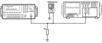
Of course, no engineer will sign papers only on the basis of even beautifully executed drawings. Spread resistance measurements will be taken.
External contour
The external ground loop is also closed. It is a horizontal grounding conductor made of a steel strip, connecting a certain number of vertical pins. The depth of this structure should be at least 70 cm from the surface, and the strip should be placed edgewise.
The device must be located around the perimeter of the building, not exceeding a distance of 1 m from its walls or foundation slab. The total circuit resistance cannot exceed 40 Ohms if the soil resistivity is less than 1 kOhm*m in accordance with the PUE.
If the substation has a metal roof, then it is grounded by connecting it to the external circuit with steel wire with a diameter of 8 mm. The connection is made from two sides of the object, diametrically opposite to each other. The requirements of the PUE require that this reduction bus on the external wall of the building be protected from corrosion and mechanical damage.
Calculation of the substation grounding device is performed to determine the resistance of the system current to propagate into the ground.
This value depends on the characteristics of the soil, the dimensions and design of the grounding device and other factors. The technique is quite extensive and requires special consideration. But it is worth noting that most often they go from the opposite. Having the required resistance and a certain grade of steel, for example, determine the dimensions of the ground electrode, the number of horizontal electrodes and the depth of burial in a known type of soil.
Grounding devices of substations or overhead lines, as well as grounding of a power plant, play an extremely important role in their operation. In addition to ensuring the normal operation of these facilities, they ensure the safety of health and life for the people serving them.
Source
What is it for?
Outdoor lighting system supports
Grounding for a network of outdoor lighting poles or overhead lines (0.4, 6-10, 20 and 35 kV) is of great importance, since it prevents the risk of electrical injury when coming into contact with structural elements in a situation where cable insulation is damaged. If there is grounding on a metal support of an outdoor lighting network or overhead line, the voltage “spreads” along the ground, thereby becoming safe for people. This indicator depends on the resistance of the soil in which the overhead line support is installed (0.4, 6-10, 20 and 35 kV). As a result, even if a violation of the overhead line insulation occurs somewhere, the structures will remain safe.
Under normal operating conditions, pin insulators mounted on supports will provide reliable insulation of all wires from structural elements. But there are situations when the voltage in the network significantly exceeds the voltage for which the overhead line was designed (0.4, 6-10, 20 and 35 kV). In such an overvoltage situation, a breakdown of the overhead line insulation is possible and, as a result, the network fails. In order to limit the value of overvoltage and improve safety, it is necessary to reduce the resistance for "current spreading". For this purpose, protective grounding is installed on overhead lines (0.4, 6-10, 20 and 35 kV) and supports for external lighting.