Overhead power lines have been familiar to us since early childhood and their presence next to us is taken for granted, as a sign of “civilization” and the availability of comfort. Like any man-made element, the technical genius of man, these power lines have their own weak points and strength limits. One of the common phenomena is sagging of the wire, caused by the destruction of the insulator, weakening of the bandage, or the presence of a foreign object on the supporting conductors (for example, a fallen tree or branches). In addition, power lines sag due to external force majeure factors, as well as deterioration of funds. In this article we will tell readers of the site for electricians how to tension the wire from the pole to the house when it is sagging, as well as when connecting the area to electricity.
Rolling out and lifting wires
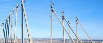
To roll out the wires, mounting rollers are hung on the supports (photo 1). The overhead line wire is hung before rolling out.
1 way of rolling
The drum is placed on special trestles or jacks. It can rotate freely on them. The end of the cable is tied to a car or tractor through a mounting roller. The car moves along the track, and the wire rolls out along the track.
2 way of rolling
The drum is placed on jacks on the car and the car with the drum moves along the track. This method minimizes damage to the wire, but is of limited use, for example for U-shaped supports.
Connecting an air supply branch to a private home
- Stretch a torso or wire between the posts and attach a current-carrying cable to it with special clamps.
- Use self-supporting wires for which support is not needed: SIP (self-supporting insulated wire). It is connected using:
- insulators (glass, polymer, porcelain);
- special fittings.
Useful tips Connection diagrams Principles of operation of devices Main concepts Meters from Energomer Precautions Incandescent lamps Video instructions for the master Testing with a multimeter
Securing bare overhead line wires to an anchor support
On the anchor support, overhead lines up to 1000 Volts, insulators are installed to secure the wire. The wire on the overhead line anchor supports is wrapped around the insulator and secured, as in Fig. 2.a.
On an anchor support, overhead lines over 1000 Volts, the wire is also wrapped around the insulator and secured with a bolted die, as in Fig. 2.c.
In Figure 2.c you see how the wires are attached to the supports of the anchor spans, with insulators in the form of garlands.
The overhead line wire loops (short branches) are connected by thermite welding or bolted connections.
Sagging standards
Let's consider the standards of the PUE chapters 2.4 and 2.5 in relation to the sagging of high voltage overhead lines.
Near roads
Horizontal distance
When crossing an overhead line
Populated area
Unpopulated area
As can be seen from the tables, the distance from the ground to the power line, as well as between wires and other objects, depends on the voltage value. For 380 volt networks, sag standards according to Chapter 2.4 of the PUE are as follows:
- Above the pedestrian area the height is not lower than 3.5 meters, and above the roadway this distance should be at a height of not lower than five meters; the input branch can be made at a height of 2.5 meters for the SIP wire.
- For lines with non-insulated conductors, the height is not less than three and a half meters above the pedestrian area, and not less than 6 meters above the roadway, a branch can be made at least 2.75 meters.
- When passing SIP near buildings, the distance from the cable to the balcony is at least one meter and at least twenty centimeters from the wire to the blank wall.
- In the case of uninsulated conductors, the distance from windows, terraces and balconies is at least one and a half meters and at least one meter along a blank wall.
- It is strictly prohibited to place overhead lines with uninsulated conductors above buildings for safety reasons.
Norms for wire sag from pole to house
Securing overhead line wires to an intermediate support
Figure 3 shows the fastening of wires without insulation on intermediate supports. Here, two types of connections are knitted (Fig. 3, a) and a supporting clamp (Fig. 3, b).
Instead of results
Let me draw your attention to the fact that the article examined the tension of the wires of an overhead power line performed with bare wires. Such an overhead line is designated, in contrast to a power transmission line with insulated SIP wires, which is designated VLI. Linear fittings of VL differ from similar fittings of VLI.
©Elesant.ru
Other articles in the section “Overhead power lines”
- Types of power transmission line supports by material
- Types of supports by purpose
- Overhead power lines with SIP wires
- Wooden supports for overhead power lines
- Reinforced concrete power transmission line supports
- Reinforced concrete power transmission line supports
- Power line support structures
- Tension of overhead power line wires
- SIP installation mistakes that should not be made
- Preparatory work for installation of overhead power lines
What to do if you witness a dangerous sagging overhead line
Under no circumstances should you be near a wire that is sagging and try to support, tie, or bite off the cable yourself for profit. This can be fatal and dangerous because... a live line is not much different from one without voltage. In one of our articles we talked about step voltage, which is closely related to damage to the cable route. We strongly recommend that you read the material.
As a rule, each line or section has an owner or a person in charge of the energy sector, who bears full responsibility for the safe operation of the equipment entrusted to him. He needs to be informed. If this is problematic, you should call the regional energy supply organization or emergency service, the Ministry of Emergency Situations, the district administration, or the mayor's office.
— Technological map for suspension, sighting and tensioning of AC type wires
1. INTRODUCTION
The technological map has been developed for the suspension of AC brand wires.
All types of work are carried out by qualified personnel in accordance with the current requirements of the “Rules for the technical operation of electrical installations of consumers” and “Inter-industry rules for labor protection during the operation of electrical installations”.
Garbage and excess soil are transported by road transport over a distance of up to 10 km to places designated by the local administration.
Hanging the AC wire includes the following types of work:
- Rolling out AC wire;
- AC wire connection;
- Preparing the AC wire for connection;
- Pulling the AC wire;
- AC wire sight;
- Securing the AC wire.
TECHNOLOGY OF WORK
2.1.SUSPENSION WIRE
Rolling out AC wire.
During the rolling out of wires, monitoring is carried out to ensure that they come off the reels correctly and are intact. Particular care is taken to ensure that the wire does not have sharp bends or twists.
If damage to the wire or cable is detected, stop rolling. A mark (bandage) is applied to the damaged area, the work manager is informed and rolling continues. Repairs are carried out later.
AC wire connection.
On overhead lines of all voltages, it is allowed to connect wires, both in spans and on supports. In this case, the connection of the wires must have good electrical contact and the necessary mechanical strength. According to the PUE, the mechanical strength of the connection must be at least 90% of the strength of entire wires or cables, and its electrical resistance must not exceed 120% of the resistance of a wire of the same length. In addition, the connection should not change its characteristics when subjected to simultaneous mechanical loads and heat.
It is allowed to connect wires in spans only using cold methods using special clamps, since during hot processing the wires are subjected to local annealing, which sharply reduces their mechanical strength. Such methods are twisting the wires, crimping them with oval connecting clamps (connectors) and crimping them with shaped ones. However, over time, the electrical resistance of such connections increases. Therefore, sometimes the ends of the wires are released from oval connectors and, after crimping or twisting, they are additionally welded with thermite cartridges, which provides connection resistance. According to the PUE, it is allowed to make no more than one wire connection per span.
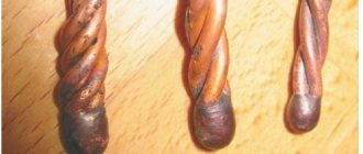
Twisted wire connection diagram
a - oval connector, b - the same, and thermite welding: 1 - ends of wires, 2 - connector, 3 - place where wires are welded
Preparing the AC wire for connection.
Before connecting, wires, connecting fittings and fixtures must be carefully checked. The material and dimensions of the oval connectors must correspond to the drawings, and the connectors and thermite cartridges must be marked according to the brand and cross-section of the wires.
For reliable electrical and mechanical connections, it is necessary to thoroughly clean the aluminum wires of the wires and the inner surface of the aluminum part of the connectors from the aluminum oxide film, which has high electrical resistance.
The prepared ends of the wires are inserted into the clamp body. Install the connector so that the extreme marks marked on it are located on the side of the cut ends of the wires being connected. When connecting copper, aluminum and steel wires, crimping is carried out along the marks sequentially from one end of the connector to the other in a checkerboard pattern, and when connecting steel-aluminum wires - from the middle of the connector, also along the marks in a checkerboard pattern.
AC wire tension.
After rolling out and lifting onto intermediate supports, the wires and cables hang freely and touch the ground in the spans between the supports, so they must be tensioned and secured to anchor supports. Anchor spans of longer length are divided into several grips.
Wires and cables are tensioned and secured in several stages. First, wires and cables are attached to the first anchor support, for which tension clamps are mounted at the ends of the wires, connected to garlands of insulators, lifted onto supports and coupled to pre-installed fastening units. Then they move to another anchor support (at the end of the span) and pull the wires to a certain sag (or force), controlled respectively by a sight or a dynamometer.
On the extended wires, mark the place where the tension clamp is attached, after which the wires are lowered to the ground, tension clamps and garlands of insulators are mounted on them, the wires are re-tensioned and finally secured to the anchor support.
Before tensioning the wires and cables, a mounting block is installed on the traverse of the second anchor support so that it is convenient to attach the tension garland of insulators to the traverse. A traction cable is passed through the mounting block, one end of which is attached to the traction mechanism (for example, to a tractor), and the second, using a mounting clamp MP or MK, is attached to the wire. Electric linemen are placed along the entire length of the anchor section, who monitor the lifting of the wires in the spans, remove caught objects and dirt, monitor the passage of connecting clamps and repair couplings through the rolling rollers, as well as roads and other obstacles over which the wires are pulled.
At the beginning of the hood, they “pick up the slack,” i.e. stretch each wire in turn so that it comes off the surface of the earth in all spans, after which they inspect it. Then, if the mechanical strength of the rigging and the power of the traction means allow, a device for simultaneously pulling three wires is attached to the wires using mounting clamps, attached to the tractor instead of the traction cable and continues to pull the wires until the required sag.
Sighting of the AC wire.
The force with which the wire (cable) is pulled and secured to the support and the sag depend on the type of wire, the length of the span, climatic conditions and the safety factor with which the wire (cable) must work on the line. To determine the forces, use installation tables or curves, in which for each brand of wire (cable) and climatic region, sag arrows are given depending on the distance between the supports and the air temperature during installation.
The tensile force of a wire can be determined both by its sag and by the readings of a dynamometer installed between the traction mechanism and the end of the wire. The most widely used method is to determine the tensile force of a wire by measuring the sag in a span of known length.
To determine the required wire sag, first select the spans in which sighting will be carried out. On short anchor spans (up to 3 km) this is the second and penultimate intermediate span, and on longer ones the wire is additionally sighted in the middle of the anchor span. For each selected span, the sag of the wire is determined according to the installation curves, depending on the length and air temperature.
For ease of sighting, the wire is initially slightly pulled, raised above the sighting line by 0.3 - 0.4 m, kept in this position for 10-15 minutes, and then lowered to the sighting line. Sometimes the overtightened wire, stretched under the influence of its own mass, “sits” on the mark.
Securing the AC wire.
At the signal from the sighting officer, the electric lineman, located on the anchor support, puts a mark on the traction cable (or wire) at the point of attachment of the tension garland to the crossbeam. After this, the tractor moves backwards and lowers the wire along the entire anchor span to the ground. Then they transfer the mark to the wire, measure from it along the wire towards the span the length of the tension garland (taking into account the intermediate links) and install the tension clamp in this place.
Tension wedge clamps are mounted in the following sequence. The clamp is disassembled, its serviceability is checked, and a gasket made of wire material is placed in the housing groove. Then insert the end of the wire into the clamp and secure it with a wedge so that the end of the clamp is at the mark on the wire. The wedge is driven into the body with light blows of a hammer. After this, the clamp with the wire is fastened to the eye of the garland of insulators.
Wedge-thong type clamps are mounted in the same way as wedge clamps, only the wire (cable) is inserted into them in a loop, tightly pressed around a double-sided wedge using an MI-24 mounting machine and secured by sliding the housing onto the clip with the wire.
Tension bolt clamps are disassembled and inspected before installation. The wire is laid in the housing on an aluminum spacer so that the mark for the mounting location of the clamp is at the exit of the wire from it into the span, and the part on which the pressure dies are located is facing the loop. Then the first pressure plate from the side of the span is placed on top of the wire with an aluminum spacer placed under it, a U-shaped bolt is inserted and the nuts are evenly tightened. They also install the second, pressure die, then the third, etc., securing the last one from the side of the loop. Attach bolted clamps to the garland in the same way as wedge clamps.
2.2. SAFETY MEASURES DURING INSTALLATION WORK
When installing wires and cables, before starting work, you should check the serviceability of lifting mechanisms, devices and installation tools. All workers involved in rolling out, lifting and tensioning wires must have a firm grasp of the signals and commands associated with the work.
When unloading and rolling drums with wire, you must ensure that their protruding parts do not catch clothing. The drums are transported and unloaded in such a way that there is no possibility of them falling to the ground. Do not drop drums from the machine. As a rule, drum unloading is mechanized. When unloading manually, the drum is lowered along the slings, pulling it with a cable or rope in the opposite direction.
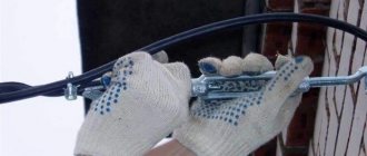
When rolling out wires, you need to check the stability of the rolling devices on which the drums and brake devices are installed and remove protruding nails. Wires are rolled out and pulled out using canvas mittens, and when rolling out manually, canvas shoulder pads are used. When rolling out and pulling wires by hand, it is prohibited to wrap yourself around the wire and put its loop on your arm or shoulder. Rolling out wires on slopes is done from top to bottom.
The rolled wire or cable must be carefully inspected and any detected defects must be eliminated, which may cause a break when pulled and cause injury. If the tension wire or cable is caught on any object on the ground, it is not allowed to approach it from the inside of the corner or from the side where the wire can jump off after being released. Do not stand under wires and cables while lifting and pulling them. When rolling out, lifting and tensioning wires and cables across roadways, traffic should not be allowed to pass until the wires are lifted to the design height and securely fastened. To stop traffic, signalmen must be posted on both sides of the crossing.
2.3 QUALITY CONTROL AND ACCEPTANCE OF WORK
It is recommended to install the speakers in compliance with the technologies given in the current technical and methodological documents, using special linear fittings, mechanisms, devices and tools, at an ambient temperature of at least minus 20°C. In this case, the following basic requirements must be observed:
— carefully prepare the overhead line route, clear the clearing, removing trees or large branches that interfere with the installation of supports, rolling out and adjusting the wires;
— when constructing an overhead line to replace the old line structures that have become unusable along the same route, they must be dismantled before installing new supports;
— take measures to prevent damage to the insulating coating of wires when rolling out and adjusting them, to prevent contact with the ground, concrete and metal structures, large tree branches;
— roll out the wires under tension;
— it is recommended to entrust the installation of wires to specially trained teams of construction and installation or operational organizations;
— strictly observe the installation forces and sag when adjusting the wires, do not allow the wires to be overtightened.
Safety rules when working with a winch
What not to do when working with a manual lever winch:
- The cable length cannot be increased. The drum must be screwed onto the factory-limited footage.
- do not overload the tool beyond the standard load
- When welding, remove the winch as far as possible so as not to damage the cable from splashes.
- When tensioning the drum, always leave at least two turns
- do not use the mechanism to lift people
- do not extend the handle yourself
- Only one person should operate the handle. It is not allowed to use the force of two workers.
When choosing a winch, of course, the ideal option would be a mechanism with less weight, a longer cable length and maximum pulling force. However, even technically it is impossible to design such a model.
Each brand has its pros and cons. Therefore, when purchasing, you will have to decide which of the characteristics are the main and highest priority in your operating conditions.
Winches LR-15 and LR-20
The Russian manufacturer KVT produces 2 types of similar winches - these are models LR-15 and LR-20.
Here are their technical characteristics and passport data:
Manual winch manual for SIP - download.
Winches in their design have:
- reinforced ratchet mechanism
- switch providing stepwise tension or release
- three forged hooks. At the same time, the main hook can be freely rotated 360 degrees for convenience during operation.
- bypass block
- handle
The market is filled with a huge number of winches that are poor copies or clones of similar tools. And the declared efforts on them do not always correspond to reality.
A high-quality tool has a body and handle that are galvanized to prevent corrosion. All hooks are equipped with safety carabiners.
Chinese models can withstand a maximum load of up to 500 kg. At the same time, the cable holds up, but all other elements begin to bend and deform.
Buy winches for SIP in specialized stores; you will not find such a tool in ordinary hardware stores. And those that will be presented for sale completely lack any intelligible accompanying technical documentation.
When choosing, always check that the winch works in both directions. That is, with its help it was possible step by step not only to tighten the SIP, but also to loosen it using a ratchet.
SIP supply to a house underground
When connecting an object to a source of electricity, sometimes difficulties arise, for example, it is necessary to install additional support or remove a tree that interferes with the laying of cables through the air. In this case, the owners of houses and dachas are interested: is it possible to lay SIP in the ground? The answer to this question can be found in GOST R 52373–2005. It states that the self-supporting insulated wire is intended exclusively for laying overhead power lines. Therefore, the use of this cable for laying an underground line will be a direct violation of current regulations.
According to the operating instructions for electrical installations, electrical products must be used in strict accordance with the manufacturer's instructions regarding the intended purpose of the product. If the technical specifications of the power supply project specify the use of a self-supporting cable, then the supply to the house must be carried out only by air. Otherwise, the connection will be incorrect.
If such a method is really necessary, then do this installation in a metal pipe, or at least in HDPE or PVC. This will protect the cable from moisture and, most importantly, rodents.
SIP supply to the house
If, according to technical conditions, the electricity meter must be installed indoors, then two options can be used to enter the cable into the house. The first method involves the use of self-supporting insulated wires for laying along the facade of the building and entering inside. The second method involves switching from a self-supporting insulated wire to a VVGng cable before entering the house. The disadvantage of the first option is the relatively low fire resistance of the SIP insulating shell, therefore it is not recommended to insert such a cable into wooden buildings. The disadvantage of the second option is the presence of a transition from a cable of one type to a wire of another type. Representatives of the energy supply organization may prohibit the use of connections to the electricity meter.
The problem is solved in the following ways:
- To increase fire safety, SIPs are introduced into a house using special corrugated hoses, metal or plastic pipes, after pre-treating their surface with a material in the form of paint or paste that is resistant to high temperatures and open fire.
- To avoid direct connection of two cables of different types, protection devices are installed on the facade of the building. An insulated wire is connected to them, and from them another cable is pulled along the facade, brought inside the house and connected to an electricity meter. To protect circuit breakers, a special box is used.
Which option to use is decided on the spot. The advantage of the first method is the absence of a protection device that requires additional protection and maintenance. The advantage of the second method is the provision of a high fire resistance without the need to use additional protective materials, as well as the protection of the cable passage through the wall of the house with an automatic switch. In this case, there is no need to install additional protective equipment upstream of the electricity meter.