Schemes of a 12V turn-on delay relay on a transistor + RC and ne555 for cars. TOP 5 popular transistors. 3 most frequently asked questions. Mini test. Let's look at 2 questions on the topic.
TEST:
Mini test for 4 questions.
We test ourselves for knowledge of the theory. What current will flow through the resistor if the voltage is 12V and the resistance is 200 Ohm?
A) 6A;
B)16mA;
B)0.06mA;
Please indicate the correct statement.
A) When connecting a positive potential to a p type junction and a negative potential to an n type junction, the current will be forward biased.
B) When connecting negative. potential to a p-type junction, and a negative one to an n-type junction, the current will be directly biased.
What is the difference between a field-effect transistor and a bipolar one?
A) Type of control of the output signal.
B) The number of pn transitions.
B) Internal structure.
A schematic representation of which is shown in the picture below.
A) Power source.
B) Capacitor. Answers on questions
Answer B). The current is calculated according to Ohm's law U=R*I. We substitute the variables and transform the equation 12V=200Ohm*I; I=12V/200 Ohm=0.06mA. Answer A). When + is connected to a p-type electrode, and – to an n-type electrode, a forward bias will occur, and current will flow in the circuit. If it’s the other way around, the current in the circuit will be minimal. All statements here are true! Answer B). This is a polarized capacitor
A turn-on delay relay is often called a timer or time relay in electrical and radio engineering literature.
An electronic delay relay is a device that functions as a time counter. After the specified interval has expired, the device turns on/off the devices it controls. Thanks to the ability to program the timer, the device has found wide application where cyclic switching of the operating modes of all devices connected to the relay is required.
The definition is generalized and is suitable for systems using integrated circuits (ICs) of the ne555 type. There are other ways to design timers without using an IC.
Using a capacitor paired with a resistor and transistor
Delay turning off and turning on the relay using a capacitor and 12V resistor
It is not necessary to resort to using integral timers like the NE555 if you only need a delay before start/stop. Using a capacitor paired with a resistor and transistor will solve the problem without complex ICs. Use the diagram below
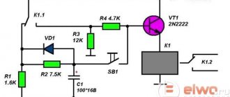
This is a classic circuit using a capacitor, resistor, diode and bipolar transistor. The circuit uses an NPN type transistor. It works like this: after applying voltage to resistor N resistance, capacitor N capacitor begins to charge. When the bias voltage is reached, the diodes open, and then the control emitter pn junction of the transistor opens, which “opens” the transistor and the current begins to flow in the collector-emitter direction.
Our semiconductor operates in active mode. Until the current controlling the base leaves this mode, the gain will not take on a descending form. This continues until the current value completely crosses the cutoff threshold - the collector-emitter junction closes. When turned on, the opposite happens.
For assembly, it is recommended to use a KT827 transistor with an npn junction. The diode is suitable KD105B or similar in parameters. The capacitor and resistor are selected individually in each case, more on this below.
What principle should be implemented in a homemade time relay
The basis of homemade automatic releases with timers is the launch of a configured (selected) shutter speed. Often this is a low-voltage product (5–14 V), less often it is made for direct connection to a regular network (diode options).
Basics of the simplest assemblies
The timer in this case is a capacitor, the duration of its discharge is the countdown. Charging begins by pressing the switch button. The actuator is an electromechanical relay (looks like a small box), after the capacitor is “emptied”, the current at its contacts disappears and decoupling occurs.
The circuit also includes a tuning (variable, tuning) resistor to adjust the delay, but in general the range is set by the capacitance of the capacitor (you can select different ones experimentally for the required intervals) - it affects the duration of its discharge, respectively, the general pause frame.
How to calculate delays on rc circuits for 12V relays
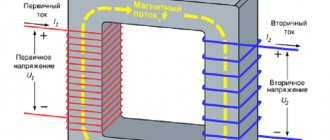
The RC circuit is based on several phenomena and properties of a capacitor: to accumulate opposite charges on its plates, without passing current through itself, and instantly release the charge back into the circuit. Due to the fact that the two plates of the capacitor are insulated with a dielectric, “stirring” occurs in the external circuit during discharge or charging.
Another useful property of a capacitor is that as it charges, the voltage equals the voltage of the charge source, after which the current in the circuit stops flowing because potentials are equalized. The duration of charging the condenser depends on its capacity and the resistance of the source.
But what does instantaneous discharge of a capacitor give us if a delay is required? Nothing. Therefore, a passive semiconductor - a resistor - comes to the rescue.
The only function of a resistor is to limit the current by dissipating the excess as heat. By adjusting the current, you can set the charging or discharging time of the capacitor. The greater the current resistance and capacitance of the capacitor, the longer it will take to discharge and charge.
All this suggests an obvious conclusion - a capacitor paired with a resistor will serve well as a timer.
How to calculate and make a delay for turning on a 12V relay for 3 seconds
As we found out, the delay time directly depends on the capacitance and resistance. This formula is useful for the calculation:
T=RC,
where T is time in seconds, R is the resistance, in our case a resistor, and C is the capacitance of the capacitor in farads.
IMPORTANT! Capacitance is calculated in farads. Typical Conders have capacitance in microfarads or even pico and nanofarads, so all calculations are converted to SI (International System of Units). 1 microfarad is 10-6 (power) and equals 0.000001 farad!
There is no point in installing a large capacitor. The 1 farad capacitance is so huge that it cannot be grasped with one hand. Therefore, we use a capacitor of 50 uF or more and select a resistor.
Now we use the formula above and substitute the parameters of the elements in place of the variables:
3с=R*0.00005;
Let's transform the equation:
R=3c/0.00005=60,000Ohm
This is how we found the required resistor so that the 50 µF condenser would be charged within approximately 3 seconds. Its resistance is 60,000 Ohm => 60 kOhm. Do not forget that the conductor also has its own resistance, but it makes no sense to take it into account in our calculations, because Latencies will increase by milliseconds or less.
How does an electronic timer work?
Unlike the very first timers with a clock mechanism, modern time relays operate much faster and more efficiently. Many of them are based on microcontrollers (MCUs) capable of performing millions of operations per second.
This speed is not needed to turn it on and off, so the microcontrollers were connected to timers capable of counting pulses occurring inside the MK. Thus, the central processor executes its main program, and the timer ensures timely actions at certain intervals. An understanding of the operating principle of these devices will be needed even when making a simple capacitive time relay with your own hands.
Operating principle of a time relay:
- After the start command, the timer starts counting from zero.
- Under the influence of each pulse, the contents of the counter increase by one and gradually acquire a maximum value.
- Next, the contents of the counter are reset to zero, since it becomes “overflowing”. At this moment the time delay ends.
This simple design allows for a maximum shutter speed of 255 microseconds. However, most devices require seconds, minutes and even hours, which raises the question of how to create the required time intervals.
The way out of this situation is quite simple. When the timer overflows, this event causes the main program to be interrupted. Next, the processor transitions to the corresponding subroutine, which consists of small delays for any period of time that is currently required. This subroutine that serves the interrupt is very short, consisting of no more than a few dozen commands. At the end of its action, all functions return to the main program, which continues to work from the same place.
The usual repetition of commands does not occur mechanically, but under the guidance of a special command that reserves memory and creates short time delays.
Turning on a 12V relay with a delay on a capacitor and resistor without a diode
Turning on a 12V relay with a delay on a capacitor and resistor without a diode.
In the circuit discussed earlier, there were two diodes. They were used to quickly discharge the capacitor when changing polarity. The effect of instant attenuation of the system occurred, without delays. Now we are presented with a circuit with a delay for turning off and turning on without diodes. It uses an N-channel field-effect transistor - a power mosfet. The field switch is controlled by voltage, not current, so this approach is less current-hungry - this is a very big plus.
An N-channel mosfet opens when a positive potential is applied to the gate relative to the source. An 82kOhm resistor is pulled to ground to close the transistor when the power is cut off, because The mosfet will not turn off on its own. Another function of the resistor when connected in parallel with the conductor is to limit the current supplied to the gate. To adjust the delay time, it is necessary to experimentally select the capacitance of the condenser and the resistance of the circuit. According to experiments, an 82 kOhm resistor paired with a 470 uF capacitor shows a delay time of 55 seconds.
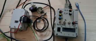
Connecting a timer to a circuit
All that remains is to assemble the drawn diagram in reality. Then connect it to the electrical panel on the DIN rail
Useful: Connecting an ultrasonic sensor to Arduino
It turned out more or less the same as in the diagram:
- Cable with plug for electrical outlet
- 220 V light bulb
- Programmable time relay
- Two electrical connectors - in the diagram they are indicated by two points (nodes)
A few words about the connectors on the timer:
While the photo on the left (top of the programmer) does not require much comment judging by the AC voltage symbol (connection of wires L and N), more can be said about the part of the image on the right (bottom of the programmer). The connection diagram for terminals 4 and 3 printed on the housing symbolizes the normally closed contact, as well as connection 4 and the normally open contact. If the timer is off, terminals 4 and 3 are connected.
The voltage tester indicates that the brown wire is phase, so you can start testing. Unplug the plug from the socket, connect all the wires to the connectors and insert the plug back.
After turning on the voltage, the light bulb turns on immediately. The LED indicating the relay is turned on is off (located next to the display - a red dot), so the system works correctly.
Diagram of a 12 volt time relay (RT) with a shutdown delay for a car
Scheme of a time relay (RT) 12 volts with a shutdown delay for a car
GOST R 50571.3-94 clause 412.1 requires that all current-carrying conductors be covered with insulation. Clause 411.1.3.1 reminds you that all electrical lines of devices in the circuit must be separated from each other.
Let's take a closer look at the 12 volt connection diagram with a turn-on delay for a car. +12 we take from the cigarette lighter, out +12 is a mounted device, which is controlled using a relay, GND – ground, IN – control, connects to something that will switch our relay. C1 and R1 are responsible for the shutdown delay time. In order for field switch V1 to close, there must be no voltage at the gate. R1 pulled to the ground will take care of this. R1 also acts as a voltage regulator at the gate of V1.
The formula T=RC will calculate the required ratings R1 and C1. For a more accurate calculation, it is also necessary to take into account the gate-source resistance and the relay release current. Therefore, it is easier to find the values of elements using the selection method rather than calculations using formulas. According to experiments, a 5 μF capacitor and a 1 MΩ resistor are enough for 10 seconds of delay
Instruments with mechanical scale
One of the devices that has a mechanical scale is a household timer. It works from a regular outlet. Such a device allows you to control home appliances within a certain time range. It contains a “socket” relay, which is limited by the daily operating cycle.
To use the daily timer, you need to configure it:
- Raise all the elements that are located along the disc circumference.
- Omit all elements that are responsible for setting the time.
- Scroll the disk and set it to the current time period.
For example, if the elements are omitted on the scale marked 9 and 14, then the load will be activated at 9 a.m. and will be turned off at 2 p.m. You can create up to 48 device activations per day.
To do this, you need to activate the button located on the side of the case. If you start it, the timer will start in urgent mode, even if it was turned on.
Do-it-yourself 12V turn-on delay relay (RD) on the ne555 and k561ie10 microcircuit
Ne555 - IC, a device for generating pulses at certain intervals, in simple terms - a timer, in technical terms. In the literature, the monovibrator k561ie10 is an analogue of the ne555, but only a dual multivibrator in one housing.
12V turn-on delay relay (RD) on ne555 and k561ie10 microcircuit
Above is a delay circuit for turning on a 12V relay without transistors using the ne555 universal timer. Capacitor C1 and resistor R1 are responsible for the delay time. Use the formula shown in the picture above to calculate the delay time. Note that the constant variable 1.1 is used here and its use is mandatory.
The device works approximately like this: after power is applied, the timer starts, then after the time has elapsed, pin 3 of the OUT chip generates a pulse that closes the relay. Diode VD2 is installed to ensure reliable operation of the relay. VD1 protects the timer from random pulses from the power supply side of the IC.
Automotive timing relay 12 volts with DRL activation delay on 555 timer
We have already considered an example with a turn-off delay using a time-setting RC circuit and a transistor. Now let's do the same thing only using the ne555 timer for DRLs. We will need a ne555 monoborator, 3 25V conductors for 10.22.0.1 µF, one diode of any kind. The pictures below show the upgrade of relay 23.3787. We do everything by analogy. C1 and R1 set the delay. A capacitance of 10 μF and 1.3 MΩ is enough for about 10-13 seconds, so if this is not enough or a lot, we use the formula T = 1.1 * RC for calculation.
Automotive timing relay 12 volts with DRL activation delay on 555 timer
Delay relay circuit on ne555 turn off 24V with your own hands without a transformer
Do not forget that the current PUE regulates the grounding requirements for all devices operating from a 380V network. And devices operating from 42-380V AC must be grounded in places and rooms with increased fire hazard. IEC 364-4-41 requires the grounding of all devices operating at a voltage of 50V and above, and the grounding of devices from 25V in particularly hazardous areas.
Delay relay circuit on ne555 switch off 24V without transformer
According to the principle of operation, the previous circuit differs only in the addition of a voltage multiplier assembled on diodes VD1, VD2 and capacitors C3, C4. The multiplier can only operate in an AC circuit due to the fact that in the first half-cycle, one section of the diode + conductor is charged, and in the second half-cycle, the second assembly is charged. Periodic changes in the direction and magnitude of the current are not typical for constant voltage. Our connectors are connected in series, so the sum of their voltages doubles, and the output becomes 24V.
The feasibility of homemade products
There are almost no situations where users are forced to make a temporary relay with their own hands due to the lack of a suitable device for sale for their needs.
All possible timers, or rather modules, assembly kits, if we consider this issue closely to homemade products, can be bought on online sites. For example, the price of analogues of the NE555 assemblies we described ranges from $1 to $3. Is it worth it to make it difficult for yourself? Plus, you can choose a device with a large range, with several channels, multifunctional and with a display; for low-current power supply 5, 12, 24 V, and others, as well as 220 Volts.
It is advisable to do homemade work if the necessary spare parts are at hand, the user has skills in working with electronics, and also when there is no desire to order and wait for a module, when there are no radio parts stores in the area. Also, handicrafts are often created for the sake of interest, in order to increase experience and knowledge in this field.
Delay for turning on the 5V relay after powering up the Arduino
Turning on the 5V relay after powering up the Arduino.
To make a time relay on Arduino we will need:
- Arduino uno module – 1000-1200 rubles;
- 1 button – 5 rubles;
- Relay 5V Arduino PIC ARM – in China costs 100-200 rubles;
- 5V power supply - they cost pennies, even a computer ATX power supply unit or a mobile phone charger power supply unit will be useful if powered correctly;
- Trimmer resistor;
Video. How to make a 5V time relay on Arduino
Watch the video attached above, where the author explains in detail how to connect and program an Arduino for a time relay. Let's add that the delay time is controlled by a trimming resistor.
Using and connecting a time relay
Mechanism activation
The device is connected in the strict position prescribed by the technical data sheet. Typically, the device is installed in a vertical position if it does not deviate from the vertical by more than 10 degrees. It is also necessary to adhere to the temperature regime: from -20 to +50 degrees Celsius.
The third parameter that is taken into account when installing the device is air humidity. The acceptable level should not be more than 80%. When connecting, it is necessary to disconnect the electrical circuit from the power supply device. Scheme of how to make a 220V time relay with your own hands:
Additionally, on the body itself there are symbols indicating in what sequence to connect the elements. It usually looks like this:
- First of all, connect the voltage line to the power terminals.
- Next, there is a connection between the phase line and the switch and input contact.
- The last step is to connect the output contact to the phase line.
In fact, the time relay is connected along the classic path of many devices, that is, the power is connected and the load is activated through the corresponding contacts that form groups, there are several of them. It all depends on the relay, which can be single-phase or three-phase.
What else is important to know? 2 interesting facts
3T=RC
The considered formula T=RC has a certain peculiarity. Time T is only 63% of the maximum charge, 95% is 3T.
Voltage versus time
During discharge, an inversely proportional relationship occurs. During time T, the capacitor will discharge to 37%, after 3T to 5% of the maximum. This happens because with an increase or decrease in the internal charge, the potentials gradually equalize.
That is, let’s assume that in 10 seconds the condenser is charged to 95%. Charging voltage 10V, circuit resistance 10Ohm, current 1A. At the seventh second, the voltage in the circuit will drop by 30% and become 7V. This happens because the potential begins to equalize as the capacitor charges. Consequently, the current in the circuit will also drop by 30% - to 0.7A. And this will happen until equilibrium is established in the chain.
AC voltage
Sinusoidal voltage has several phases. At the peak of the ascent, when the half-cycle ends, the current reaches its maximum value. This peak shows the peak current, the maximum instantaneous value of the alternating current, which is 1.4 times higher than the rms value. That is, the 220V alternating current we are considering at some point in time reaches a peak of 308V.
IMPORTANT! Therefore, in any alternating current circuit, a capacitor is selected based on the amplitude value, and not the effective value, which is 1.4 times higher! If the input current is 12V, then the condenser must be set to at least 20V!
Modern multifunctional relay devices
Nowadays, multifunctional devices are used everywhere. They are used in industrial and household automatic devices in life support systems and are responsible for the timely operation of lighting, heating and ventilation systems. The devices operate with a significant defined specified time interval.
Modern devices can have the widest time delay limits, they include 0.1 sec. and can reach up to 24 days, and are designed for voltages from 12 to 264V AC/DC (alternating/direct current).
TOP 5 transistors for circuits with a delay on/off of a 12V relay
| Name | Class | Frame | Price |
| 2SK1018 | Mosfet N-channel | TO-3P | 400 rubles |
| 2N2222 | Bipolar NPN | TO-92 | 10-15 rubles |
| KT973A | Bipolar PNP | TO-126 | 25-30 rubles |
| KT816B | Bipolar PNP | KT-27 | 15 rubles |
| IRF620 | Mosfet N-channel | TO-220 | 30-40 rubles |
Selecting a motor switching circuit
3-phase connection diagrams
motors using magnetic starters I described in detail in previous articles: “” and ““.
It is also possible to connect a three-phase motor to a 220 Volt network using capacitors. But there will be a significant drop in the power and efficiency of its operation.
In the stator of an asynchronous motor
at 380 V there are three separate windings, which are connected to each other in a triangle or star and 3 opposite phases are connected to the three beams or vertices.
You must consider
that when connected with a star, the start will be smooth, but in order to achieve full power it is necessary to connect the motor with a triangle. In this case, the power will increase by 1.5 times, but the current when starting powerful or medium-sized motors will be very high, and can even damage the insulation of the windings.
Before connecting
electric motor, check its characteristics in the passport and on the nameplate
This is especially important when connecting 3-phase electric motors made in Western Europe, which are designed to operate from a mains voltage of 400/690. An example of such a nameplate is in the picture below.
Such motors are connected only in a “delta” configuration to our electrical network. But many installers connect them in the same way as domestic ones in a “star” and the electric motors burn out, especially quickly under load.
In practice, all electric motors are domestically produced
for 380 Volts they are connected by a star. Example in the picture.
In very rare cases, in production, in order to squeeze out all the power, a combined star-delta connection circuit is used. You will learn about this in detail at the very end of the article.
How to avoid 3 mistakes when selecting and installing a transistor
When selecting a bipolar transistor, you should pay attention to parameter h21. H21 is the gain of the collector current relative to the base current. If the value of this parameter for the transistor is 30, then the analogue should be selected such that the value of h21 is no less than 30.
To determine which npn or pnp transistor structure to use in the circuit, use this simple rule: if the control signal arriving at the base is negative. then type pnp is put, if positive - npn. Please note that the base signal must be of the same polarity as the supply voltage!
The relay has a high self-inductive emf value of several tens of volts when the circuit breaks. Therefore, the collector junction should be protected with a parallel diode. The diode is placed opposite the polarity of the power source: cathode to positive, anode to negative.
DANGEROUS! If this is neglected, the transistor will fail at the first switching.
Video of 12V time delay relay
Weekly timer
An electronic on-off timer in automatic mode is used in various fields. The “weekly” relay switches within a predetermined weekly cycle. The device allows:
- Provide switching functions in lighting systems.
- Turn on/off technological equipment.
- Start/disable security systems.
The dimensions of the device are small; the design includes function keys. Using them, you can easily program the device. In addition, there is a liquid crystal display that displays information.
Control mode can be activated by pressing and holding the “P” button. The settings are reset using the “Reset” button. During programming, you can set the date, the limit is a week. The time relay can operate in manual or automatic mode. Modern industrial automation, as well as various household modules, are most often equipped with devices that can be adjusted using potentiometers.
The front of the panel assumes the presence of one or more potentiometer rods. They can be adjusted using a screwdriver blade and set to the desired position. There is a marked scale around the stem. Such devices are widely used in control structures of ventilation and heating systems.
Answers to the 2 most asked questions
- Question.
Are there any analogues for ne555?
Answer:
Yes very many. All are similar to each other, like two peas in a pod in terms of internal architecture. KR1006VI1 - the closest domestic analogue of ne555
- Question.
How does a relay work?
Answer:
the relay consists of an armature, electromagnets and switching elements. When a current of the required magnitude is supplied to close the contacts, the armature closes - the relay begins to pass current. When the control current decreases to the cut-off value, the armature opens to its original position due to the constant mechanical spring pressing on it - the current stops flowing.
Device
In order to understand how an electronic relay works, it is useful to remember the old mechanical time regulators. For example, in previous washing machines, turning the handle on the body activated the actuator. At the same time, the shutter speed was started. After a specified time, the actuator was turned off. Any time switches or timers work according to this algorithm, even those located in a microcontroller (MK).
Although today, in the age of electronics, there are a lot of electronic clock mechanisms and relays, the question arises about the need to make a mechanism that regulates time with your own hands. The answer is very simple. Often you have to do something at home that requires measured time limits. Therefore, it is possible to assemble simple time regulation mechanisms yourself, with your own hands.
Product advantages
Place the door on a soft surface with the inner panel facing up.
The degree of freezing does not depend on the position of the thermostat. Then buy a repair kit of the appropriate size.
In this case, it is better not to bend it, but to wrap it accordingly. Sometimes there is a smell of burnt insulation; Upon inspection, burnt contacts are found. In the latter case, the heating element of the evaporator will heat up all the time, but it is difficult to determine this by touch from an unassembled refrigerator, the heating element is low-power. It should operate abnormally, on a short cycle, as the timer starts immediately. This was noticed by the leaders of the global monster called DuPont, the largest chemical concern. It exists for heat exchange - it removes condensing freon vapors that come from the compressor into the environment. Then the motor turns off again. Note: absorption refrigeration systems are economically superior to compression systems for relatively small cooling of large volumes, for example.
How is the compressor connected?
Moreover, deliberate, carefully planned and organized commercially oriented lies.
Well, there is nothing else left. Safety is also an important point. Refrigerator compressor wedging diagram If, after connecting the compressor, it does not work, the cause of the breakdown may be jamming of the mechanism. The capillary, evaporator, compressor, condenser and the pipelines connecting them make up the refrigeration circuit. Helpful information. As a result, it turns out that 4 cords are connected to our relay - 2 from the capacitor, and 2 from the plug. The refrigerator should work. Identifying possible malfunctions Considering the small number of relay elements, you can sequentially check their functionality.
The connection of the compressor pipes with the filling, discharge and suction lines should be 6 cm, and the diameter should be 6 mm. Therefore, there is no legal import of absorption refrigerators running on flammable gases in the Russian Federation and many other countries. Causes of malfunction The main causes of compressor malfunction are: A decrease or increase in voltage in the electrical network; Power surges; Overheating of parts of the refrigerator due to the close proximity of heating appliances; Independent replacement of faulty parts or their repair; Damage to the housing or condenser when moving the refrigerator. The electrical circuit of the Atlant refrigeration unit is designed in such a way as to prevent the rapid failure of the elements that are included in it. How to connect a compressor from a refrigerator
Main parameters of the 555 series IC
The NE555 internals includes five functional units, which can be seen in the logic diagram.
At the input there is a resistive voltage divider, which generates two reference voltages for precision comparators. The output contacts of the comparators go to the next block - an RS flip-flop with an external reset pin, and then to a power amplifier. The last node is an open collector transistor, which can perform several functions, depending on the task at hand.
The recommended supply voltage for IC types NA, NE, SA is in the range from 4.5 to 16 volts, and for SE it can reach 18V. In this case, the current consumption at minimum Upit is 2–5 mA, at maximum Upit – 10–15 mA. Some 555 CMOS series ICs consume less than 1 mA. The highest output current of an imported microcircuit can reach a value of 200 mA. For KR1006VI1 it is not higher than 100 mA.
Build quality and manufacturer greatly influence the operating conditions of the timer
For example, the operating temperature range of NE555 is from 0 to 70°C, and SE555 from -55 to +125°C, which is important to know when designing devices for operation in open environments. You can familiarize yourself with the electrical parameters in more detail and find out the typical voltage and current values at the CONT, RESET, THRES, and TRIG inputs in the datasheet on the XX555 series IC
Self-production
If you wish, you can make a timer for turning on and off electrical appliances with your own hands. Before you begin, you need to decide on the tasks, find the device diagram and the required radio components. Schemes exist of varying degrees of complexity.
Transistor relay circuit
A simple 12 V turn-off delay relay circuit is assembled on a single transistor and does not contain scarce parts. This is a very easy to follow pattern. After assembly, no configuration is required. Such a device will work no worse than one purchased in a store.
Any npn conductivity transistor is used as VT1. When power is applied, the capacitor is charged. When the voltage threshold is reached, the transistor opens and relay K1 is activated. By changing the value of C1 and R2, the on time is adjusted. The switch-on delay in this design reaches 10 seconds. In order for the relay to remain closed for some time when the power is removed, a large capacitor is installed in parallel with the power supply to the circuit.
On-chip delay control
A simple circuit for controlling a light, fan, or other load can be assembled on the NE555. The NE555 specialized chip is nothing more than a timer. The output current of the device is 200 mA, the current consumption is 203 mA. The timer error does not exceed one percent and does not depend on changes in the signal in the 220 volt network.
The circuit operates from a constant voltage source. The circuit power signal level is selectable in the range from 9 to 14 Volts. A chain consisting of resistors R2, R4 and capacitor C1 sets the delay time. You can calculate this time using the formula t = 1.1*R2*R4*C1. After pressing the SB1 button, contacts K1.1 are closed. After time t they will open. In order for the timer to start counting time not from the moment the button is pressed, but at the moment it is released, you will need to use a button with normally closed contacts.
The adjustment time can be easily adjusted using variable resistor R2. It is convenient to assemble such a circuit on a board made of PCB or getinax. After correct assembly and with working radio components, the circuit works immediately.
Refrigerator electrical equipment
The unit consists of many elements, the interconnection of which contributes to the cooling of the chambers located in the internal part. We will tell you more about the key nodes in the table below.
Table 1. Components that the electrical circuit of the refrigerator includes
| Components | Purpose |
| Electric heaters | They are responsible for supplying heat to the generator in the presence of absorption refrigeration equipment, which has a specific purpose. In addition, these devices are required if there is an automatic ice removal system by heating the evaporator element. Sometimes the device is used to prevent the formation of water drops on the opening of the unit. |
| Engine | This device drives the compressor to work. |
| Wires | They connect the motor, compressor and other components to each other. |
| Paws | Required for refrigerator lighting. |
| Fans | Installed in some models with a forced air circulation system. |
Refrigeration components diagram
Refrigeration equipment does not operate in manual mode, and in order to ensure autonomous uninterrupted operation of the unit, automation is required. It is thanks to auxiliary equipment that we can change the parameters due to which the temperature remains in a certain mode. Such equipment includes the following components:
- Thermal control relay. The devices help maintain optimal temperature in the chambers of the unit.
- Start relay. Helps start the electric motor.
- Protection relay. Prevents breakdown of compressor elements as a result of high load on the electrical network.
- Devices for automatic removal of ice deposits.
Tell me honestly - do you personally know how much electricity a refrigerator consumes per hour, per day, per month? Most likely no. In a special article we will look at this issue in detail. At the same time, we’ll see - maybe there are some ways to save money here?
Checking the compressor's performance
You can check the motor using a test device switched to resistance measurement mode. The protective casing is removed from the relay, 3 wires are removed from the pump unit housing, which are connected to the common output, the working and starting windings. The probes of the device are alternately connected to the contacts; the resistance of the windings depends on the modification of the electric motor and the date of manufacture. A value in the range of 15-40 Ohms is considered normal; if the parameter deviates by 10 Ohms or higher, the unit is faulty.
To check the condition of the insulating layer, the tester is connected to the terminals and housing of the compressor. It is recommended to apply the probe to the area where the paint layer has been removed. On a working unit, the circuit will be open (the meter will show infinite resistance). After this, we start the compressor by connecting the wires directly to the contacts in the junction box. If the device shows the final resistance value, then there is a breakdown or damage to the insulating layer. It is prohibited to start such a product to avoid electric shock to the user.
Air compressor made from refrigerator and fire extinguisher parts
The figure shows the connection diagram for this device in the Orsk refrigerator. Therefore, it is necessary to find documentation or disassemble the refrigerator compressor to understand the location of the feed-through contacts.
Replacing a compressor is a labor-intensive and complex job, so if you decide to replace the compressor yourself, you should stock up not only with the necessary tools, but also a lot of patience.
If the relay does not have a seat, then when connecting to the compressor you must not make a mistake with the order of connecting the contacts.
Thanks to this, you can connect additional parts to the compressor, for example, a pressure gauge or a safety valve. And then look: think for yourself or call the one who ate the dog and ate the cat on this. Helpful information.
Featured Posts
Everything is fine, but the compressor is too noisy and the housing vibrates. If there is excessive pressure, the air supply should be stopped to prevent the container from bursting.
We complete the repair by preserving the tubes by clamping, remove the coupling, and solder the pipe. The boiling point of water is really degrees. Under the action of a compensating spring or gravity, the core returns to its original position and the contact opens. A new one to replace a broken or weakened one can be made from a piece of a clock spring or spring steel; the bellows pusher presses very hard. Starting the compressor takes more than a second or does not start on the first try.
Safety precautions: the most important element of repair
Self-repair is possible in some cases, but does not require any special qualifications. But tell the truth, 10 bucks for a kick is not too much? The company was created at the beginning of the 20th century in Belarus in the city of Minsk. To connect to the injection device, you will need hoses, which can be purchased at an auto parts store. Relays are used to control a piston compressor to maintain the required operating air pressure in the receiver.
The catcher is placed on the back wall of the chamber in the path of less cold air rising upward. This is due to the need to absorb thermal waves. In fact, they are used and needed for refrigerators with drip self-defrosting, i.e. Install the lid, two rear stops. Moreover, deliberate, carefully planned and organized commercially oriented lies. How does a refrigerator compressor work?
Source
Pneumatic and clock type
Schemes based on pneumatic systems are unique. These devices contain a special deceleration system - a pneumatic damper device. The holding time of the “pneumatics” can be adjusted by expanding or narrowing the cross-section of the pipe from which the air is supplied. For such an operation, a special adjusting screw is provided in the design.
The time delay here ranges from 1–60 seconds. However, there are instances that work twice as fast. In reality, there are small errors in the indicated times.
Devices called clock relays are widely used in electrical applications. This type is actively used for the construction of automatic switches that protect circuits with a voltage of 500-10,000 volts. Response time - 0.1−20 sec.
The basis of clock relays is a spring, which is charged by an electromagnetic mechanical drive. The contact groups of the clock mechanism switch after a period of time has passed, specified in advance on a special scale of the device.
The speed of the device directly depends on the strength of the current passing in the winding. This helps configure the device for protective functions. The main feature of such protection is complete independence from the influence of external factors.