Voltage from a hydraulic point of view
You have all seen and can imagine what a water tower or just a water tower looks like. Roughly speaking, this is a large, tall “glass” filled with water.
water tower
So, let’s imagine that the tower is filled to the top with water. It turns out that at the moment there is wow pressure at the bottom of the tower!
water tower filled with water
What if you drained at least half the water from the tower? The pressure at the bottom of the tower will be halved. Let's pour one bucket of water into the empty tower! The pressure on the bottom of the tower will be negligible.
Imagine this situation. We have a water carrier, and we plugged the hose with a stopper.
The water seems ready to run, but there is nowhere to run! The plug tightly clogs the hose. But the plug itself is now under pressure created by the pumping station. What does the pressure on the plug depend on? I think it’s clear that it depends on the power of the pump. If the pump power is high, the plug will fly out at the speed of a bullet, or the pressure will rupture the hose if the plug sits tightly in the hose. In this case, pressure is created using a pump. That is, we can say that this is a model of a water tower in a horizontal position.
The same can be said about the water tower. Here the pressure on the bottom is created by gravitational force. As I already said, the pressure at the bottom of the tower depends on how much water is in the tower at the moment. If the tower is filled to capacity with water, then the pressure at the bottom of the tower will be high, and vice versa.
Now imagine the pressure at the bottom of the ocean, especially in the Mariana Trench! What can be said about pressure in these two cases? It seems to be there, but the water molecules stand still and don’t move anywhere . Remember this moment. There is pressure, but there is no movement.
Origin
The difference between AC and DC lies in their origin. Direct current can be obtained from galvanic cells, such as batteries and accumulators.
It can also be obtained using a dynamo - this is an outdated name for a direct current generator. By the way, with their help, energy was generated for the first electrical networks. We talked about this in an article about the discoveries of Nikola Tesla, in notes about the war of ideas between Tesla and Edison. Later this was the name given to small generators used to power bicycle headlights.
Alternating current is also produced using generators, nowadays mostly three-phase.
Also, both voltages can be obtained using semiconductor converters and rectifiers. So you can rectify alternating current or get the same by converting direct current.
Electrical voltage
This pressure on the bottom is the same tension (by analogy with hydraulics). In this case, the bottom of the tower is zero, the initial reference level. The initial reference level in electronics is taken to be the terminal of a battery or accumulator with a minus sign. You could even say that the water level in the tower of a 12V car battery is higher than the water level of a 1.5V AA battery.
So, by analogy with electronics, this pressure is called voltage . For example, you have probably heard such an expression more than once, like “the power supply can produce from 0 to 30 Volts.” Or, in childish language, create “electrical pressure” at your terminals (marked in the photo) from 0 to 30 Volts. The zero level, where the electrical pressure is measured, is indicated by a minus.
DC power supply
Electrical voltage does not mean that electric current flows in an electrical circuit. In order for an electric current to appear, electrons must move in one direction, but at the moment they are stupidly standing still. And since there is no movement of electrons, then there is no electric current.
From an electronics point of view, there is pressure on one probe of the power supply, but not on the other. That is, this is the ground on which the tower stands, if we draw an analogy with hydraulics. Therefore, they try to make the positive probe of the power supply and indeed all devices red, like, beware, there is high pressure here! And the negative probe is black or blue.
In electronics, to indicate which terminal has more “electrical pressure” and which has less, two signs are put down: plus and minus , respectively positive and negative . On the positive side there is excess “pressure”, and on the negative side there is zero pressure.
Therefore, if you close these two terminals together, the electric current will flow from plus to minus, but it is highly not recommended to do this directly, since this will already be called a short circuit.
From theory to practice
Example 1. Let's consider the choice of a circuit breaker for DC networks using the example of molded case circuit breakers of the Tmax series.
Installation parameters: Network type: with one grounded polarity (negative only) Installation voltage: Un = 250 V DC Rated CURRENT consumed by the load: V = 450 Short circuit current: 40 kA
The following conditions must be met for the selected circuit breaker: Ue ≥ Un Icu ≥ Ik In ≥ Ib
As a rule, manufacturers have tables for selecting DC devices; the examples below provide the necessary excerpts from them. In accordance with the type of network, it is necessary to select a table related to a network with one grounded polarity (see Table 1).
Table 1. Options for connecting the poles of Tmax molded case circuit breakers for operation in a network with one grounded polarity (in the connections under consideration, the negative polarity is grounded)
* Grounding must be done on the supply side of the circuit breaker
Select the column with the network voltage greater than or equal to the voltage of the electrical installation. The required line is selected according to the rated continuous current ME of the circuit breaker, which must be greater than or equal to the load current. In accordance with the conditions specified in the example, you should select a Tmax T5 circuit breaker with Iu=630A.
The design for breaking capacity (NS, etc.) is determined taking into account the fulfillment of the condition Icu>Ik. In this case, you can choose version S, since Ik = 40 kA.
The specified requirements are met by two pole connection schemes; if the grounded pole of the network must be disconnected, then the following option should be selected:
Among the rated currents available for the thermomagnetic release of the T5S630 circuit breaker, In = 500 A can be selected, therefore it is permissible to use the three-pole thermomagnetic circuit breaker T5S630 TMA500. The device uses two poles connected in series on an insulated polarity and one on a grounded polarity. In this case, when choosing a circuit breaker with a thermomagnetic release, it is necessary to take into account the short-circuit correction factor. 2
Example 2. Let's consider the choice of an air circuit breaker using the Emax series as an example.
Installation parameters: Network type: isolated Installation voltage: Un = 500 V DC Rated current consumed by the load: In = 1800 A short circuit current: 45 kA
Voltage formula
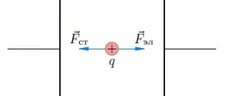
There is a formula in physics, although it has no practical application. The official formula is written like this.
voltage formula
Where
A is the work done by the electric field to move a charge along a section of the circuit, Joules
q - charge, Coulomb
U—voltage on a section of the electrical circuit, Volts
In practice, the voltage across a section of a circuit is derived through Ohm's law.
voltage from Ohm's law
Where
I - current, Amperes
R - resistance, Ohms
What is the working principle of alternating current
The English abbreviation AC (Alternating Current) denotes a current that changes its direction and magnitude over time periods. The sinusoid segment “~” is its conventional marking on devices. Applying after this icon and other characteristics is also used.
Below is a figure with the main characteristics of this type of current - nominal frequency and operating voltage.
It should be noted the features of the change in the left graph, made for a single-phase current, in the magnitude and direction of the voltage with the transition to zero over a certain period of time T. For one third of the period, three sinusoids are shifted for a three-phase current on another graph.
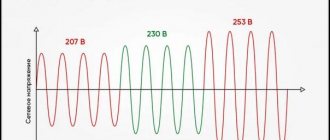
O and “b” indicate phases. Any of us has an idea of the presence of 220V in a regular outlet. But for many it will be a discovery that the maximum or otherwise called amplitude value is greater than the acting value by an amount equal to the root of two and is 311 Volts.
Obviously, in the case of direct current, the parameters of direction and voltage remain unchanged, but for alternating current, a transformation of these quantities is observed. In the figure, the opposite direction is the area of the graph below zero.
Let's move on to frequency. This concept means the ratio of periods (full cycles) to a conventional unit of time for a changing current. This indicator is measured in Hertz. The standard European frequency is 50, in the USA the applicable standard is 60G.
This value shows the number of changes in the direction of the current in one second to the opposite and return to the original state.
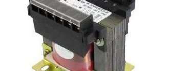
Alternating current is present when consumer devices are directly connected to electrical panels and sockets. For what reason is there no direct current here? This is done in order to be able to obtain the required voltage in any quantity by using transformers without any significant losses. This technique remains the best way to transmit power on an industrial scale over significant distances with minimal losses.
The rated voltage, which is supplied by powerful generators of power plants, at the output is about 330,000-220,000 Volts. At a substation located in the consumption area, this value is transformed to 10,000V with a transition to a three-phase version of 380 Volts. A separate house is supplied and single-phase voltage reaches your apartment. The voltage between zero and phase will be 220 V, and in the shield between different phases this figure is 380 Volts.
Current voltage - what does it mean?
This term can be heard very often in colloquial speech. Current, in this case, is electric current. It turns out that current voltage is the voltage of electric current. It's just how we shorten it. As I said above, current can be alternating or constant. Direct current and constant voltage are synonymous, as are alternating current and alternating voltage. It turns out that the phrase “current voltage” tells us what the voltage is between two points or wires in an electrical circuit.
For example, to the question “what is the current voltage in the socket” you can safely answer: alternating current 220 Volts,” and to the question “what is the current voltage of a car battery,” you can answer “12 Volts DC.” So don't be scared).
Prospects for the development of electric rolling stock
Today, due to the high cost of the current infrastructure and the presence of a huge fleet of rolling stock, it is not economically feasible to convert roads from permanent to variable, but instead of converting the contact network, engineers took a different route.
It is possible to change the rolling stock - the second way is to create dual-power electric locomotives capable of operating on both direct and alternating current, and switching operating modes on them is as automated as possible. Today, such machines not only exist on paper or as prototypes, such locomotives are successfully working for the benefit of Russian Railways - Double Power Electric Locomotives.
In preparing the material we used: Marquardt K. G. Contact network. 4th ed. reworked and additional Textbook for railway universities
DC and AC voltage
Voltage can be constant or variable . In colloquial speech you can often hear “direct current” and “alternating current. Direct current and constant voltage are synonymous, as are alternating current and alternating voltage.
In the example above, we looked at constant voltage . That is, the water pressure on the bottom of the tower is constant over time . As long as there is water in the tower, it puts pressure on the bottom of the tower. It seems that everything is elementary and simple. But what kind of voltage is called alternating ?
Everyone loves to swing on a swing:
First you fly in one direction, then braking occurs, and then you fly back with your back and the whole process repeats again. AC voltage behaves exactly the same. First, the “electrical pressure” presses in one direction, then the braking process occurs, then it presses in the other direction, braking occurs again and the whole process repeats again, like on a swing.
Hard to understand? Then here is another example from the famous book “First Steps in Electronics” by Shishkov. We take a closed system of pipes with water and a piston. Our piston is in motion. Consequently, our water molecules deviate in one direction:
then to the other:
AC voltage
Electrons behave the same way. On your 220V home network they fluctuate 50 times per second. Back and forth, back and forth. This number of oscillations per second is called Hertz. In the literature it is simply written “Hz”. Then it turns out that the voltage fluctuation in our sockets is 50 Hz, and in America it is 60 Hz. This is related to the rotation speed of the generator in power plants. In colloquial speech, constant voltage is called “constant”, and variable voltage is called “permenka”.
A Brief History of Electricity
Who invented electricity? And no one! People gradually understood what it was and how to use it.
It all started in the 7th century BC, on one sunny (or maybe rainy, who knows) day. Then the Greek philosopher Thales noticed that if you rub amber on wool, it will attract light objects.
Then there were Alexander the Great, wars, Christianity, the fall of the Roman Empire, wars, the fall of Byzantium, wars, the Middle Ages, the Crusades, epidemics, the Inquisition and more wars. As you understand, people had no time for any electricity or ebonite sticks rubbed with wool.
In what year was the word “electricity” invented? In 1600, the English naturalist William Gilbert decided to write the work “On the Magnet, Magnetic Bodies and the Great Magnet - the Earth.” It was then that the term “electricity” appeared.
One hundred and fifty years later, in 1747, Benjamin Franklin, whom we all love very much, created the first theory of electricity. He viewed this phenomenon as a fluid or immaterial liquid.
It was Franklin who introduced the concept of positive and negative charges (before that, glass and resin electricity were separated), invented the lightning rod and proved that lightning is electrical in nature.
Everyone loves Benjamin, because his portrait is on every hundred dollar bill. In addition to his work in the exact sciences, he was a prominent political figure. But contrary to popular belief, Franklin was not the President of the United States.
Next will be a list of discoveries important for the history of electricity.
1785 - Coulomb finds out with what force opposite charges attract and like charges repel.
1791 - Luigi Galvani accidentally noticed that the legs of a dead frog contracted under the influence of electricity.
The operating principle of the battery is based on galvanic cells. But who created the first galvanic cell? Based on Galvani's discovery, another Italian physicist Alessandro Volta created the Volta column in 1800, the prototype of the modern battery.
At excavations near Baghdad, they found a battery more than two thousand years old. What ancient iPhone was recharged with its help remains a mystery. But we know for sure that the battery has already run out. This case seems to say: maybe people knew about electricity much earlier, but then something went wrong.
Already in the 19th century, Oersted, Ampere, Ohm, Thomson and Maxwell made a real revolution. Electromagnetism was discovered, induced emf, electrical and magnetic phenomena were linked into a single system and described by fundamental equations.
By the way! If you don’t have time to deal with all this yourself, our readers are now offering a 10% discount on any type of work
The 20th century brought quantum electrodynamics and the theory of weak interactions, as well as electric cars and ubiquitous power lines. By the way, the famous Tesla electric car runs on direct current.
Of course, this is a very brief history of electricity, and we have not mentioned very many names that influenced progress in this field. Otherwise, a whole multi-volume reference book would have to be written.
Three phase current
A three-phase system is an electrical circuit system operating on three circuits in which forces of the same frequency act, but are out of phase from each other by one-third of a period or 120 degrees. Each individual circuit of such a system is called a phase, and a system of three phase-shifted currents is called three-phase current.
Almost all modern generators in homes and power plants are three-phase current generators. In fact, this is one large generator consisting of three small motors that generate currents, the electromotive forces in them are shifted relative to each other by 120 degrees or one third of the period.
Two-phase current
Two-phase current is when two currents of different directions are transmitted at once. The voltage parameter for a two-phase network is shifted in phase by an angle of 90 degrees. This current is transmitted by two conductors: two phase and two neutral. Used in AC electrical networks. To do this, use two circuits, the values of which are shifted in phase by 90 degrees. Each circuit uses four lines - two for each phase. Sometimes one wire with a larger diameter than the other two is used. The advantage of two-phase networks was the smooth start of electric motors, but they were supplanted by three-phase ones.