For DC motors with sequential excitation, as well as for motors with independent excitation, two braking methods are used: dynamic (rheostatic)
braking and
counter-
.
Taking into account the features of DC motors with sequential excitation, they can implement two types of rheostatic braking: braking with independent excitation
and inhibition with
self-excitation
.
Braking in independent excitation mode
When braking in the independent excitation mode, the excitation winding is disconnected from the armature winding and connected to an external source of direct current, and the armature of the electric motor is disconnected from the network and closed to the braking resistance.
Diagram of a series-excited DC motor during dynamic braking in the independent excitation mode.
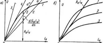
The characteristics in braking modes are described by the equations:
ω = (Iа·Ra) / (CM·Фδ)
ω = -[(M Ra) / (CM Фδ)2]
These are straight lines passing through the origin. The slope of these lines depends on the magnitude of the additional resistances included in the armature circuit.
Characteristics of a series-excited DC motor during dynamic braking in the independent excitation mode. Rext.3>Rext.2>Rext.1
Dynamic braking.
The need for such braking arises in the case when, after disconnecting the engine from the network, its armature continues to rotate under the influence of the kinetic energy of the moving masses of the electric drive. If at the same time the armature winding, disconnected from the network, is shorted to a resistor rt, then the engine will switch to generator mode (the field winding must remain connected to the network) . The electricity generated in this case is not returned to the network, as happens with regenerative braking, but is converted into heat, which is released in the resistance
In the dynamic braking mode, the armature EMF does not change its direction, but since the armature is disconnected from the network (U = 0), the armature current will change direction, since an EMF Ea will be created
those. will become negative. As a result, the electromagnetic torque will also change direction and become braking (Fig. 13.15, b). The braking process continues until the armature stops completely (n = 0).
Self-excited braking
During self-excited braking, the field winding is not disconnected from the armature, but is switched using a control circuit so that the direction of the current in the field winding remains the same as in motor mode.
Circuit diagram of a series-excited DC motor for dynamic braking with self-excitation.
Characteristics of a series-excited DC motor during dynamic braking with self-excitation. Rext.3>Rext.2>Rext.1
For the emergence and existence of a self-excitation mode, it is necessary to satisfy such a condition as the presence of residual magnetism, and the flow of residual magnetism must coincide in direction with the main magnetic flux, which is why it is necessary to maintain the direction of the magnetic flux the same as it was in the motor mode.
Braking in the self-excitation mode occurs slower than in the independent excitation mode, since the braking characteristics are nonlinear.
DC motor braking
In electric drives with DC electric motors, three braking methods are used: dynamic, regenerative and counter-braking.
Dynamic braking of DC motor
carried out by short-circuiting the armature winding of the motor or through a resistor. In this case, the DC electric motor begins to work as a generator, converting its stored mechanical energy into electrical energy. This energy is released in the form of heat in the resistance to which the armature winding is closed. Dynamic braking ensures precise motor stopping.
Regenerative braking of DC motor
is carried out in the case when the electric motor connected to the network is rotated by the actuator at a speed exceeding the ideal idle speed. Then eh. d.s induced in the motor winding exceeds the value of the network voltage, the current in the motor winding changes direction to the opposite. The electric motor switches to operating in generator mode, supplying energy to the network. At the same time, a braking torque occurs on its shaft. This mode can be obtained in the drives of lifting mechanisms when lowering a load, as well as when regulating the engine speed and during braking processes in DC electric drives.
Regenerative braking of a DC motor is the most economical method, since in this case electricity is returned to the network. In the electric drive of metal-cutting machines, this method is used to control the speed in the G - DPT and EMU - DPT systems.
DC motor back-braking
carried out by changing the polarity of voltage and current in the armature winding. When the armature current interacts with the magnetic field of the field winding, a braking torque is created, which decreases as the motor speed decreases. When the electric motor rotation speed is reduced to zero, the electric motor must be disconnected from the network, otherwise it will begin to turn in the opposite direction.
There are static and dynamic operating modes of engines. In static mode ω=const; IЯ=const; UDV=const and it is described by the so-called mechanical characteristics
.
In static mode, the independent excitation motor is described by the following system of equations:
Since the motors used in automatic control systems are controllable, there are two types of control of DC motors - armature control and pole control.
With anchor control, the voltage supplied to the armature circuit changes without changing the excitation. With pole control, on the contrary, the excitation field changes by changing the current in the windings of the main poles iB. To expand the control range, combined control is also used.
With pole control ФB=const, therefore the equation of mechanical characteristics according to
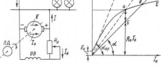
The electric machine operates in motor mode at 0K.Z., at M>MK.Z. the engine rotates in the opposite direction under the influence of an external torque - the machine operates in brake mode (counter-switching mode), when ω>ω0 the machine operates in generator mode for a network with voltage UH.
For idle speed, when M=0, this characteristic has the form of a hyperbola
The DC motor as a dynamic system is described by the following equations in operator form:
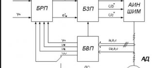
Based on these equations, a block diagram of the engine as a dynamic system can be constructed
where is the transmission coefficient, is the armature time constant, is the electromechanical time constant.
Using the Heaviside formula, transient processes can be constructed using transfer functions, for example, when starting an engine, as shown in.
Rice. 5-7b. Transient process when starting a DPT.
At TM»TYa, as is usually the case, we obtain expressions for current and speed at start-up:
To analyze the dynamics of a DC motor with pole control, equations similar to those in deflections are considered, since the control characteristic with pole control is nonlinear.
The system is linearized for small deviations relative to some zero values, presenting the variables in the following form:
; ; ; ;
Then, based on the equations, you can write the equations in deviations (at TЯ=0).
Based on these equations, a block diagram of the motor as a dynamic system with pole control ( ) can be constructed.
Rice. 5-8a. Block diagram of a DC motor with pole control.
Using this circuit, we obtain the transfer function for the DC motor with pole control
Using this transfer function, using the Heaviside formula, it is possible to obtain the transient curves in the engine with a step change in the excitation voltage, shown in.
Rice. 5-8b. Transient process when starting a DC motor with pole control.
Characteristics of the two with the last and unexcited excitation
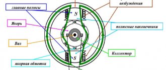
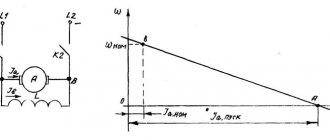
25) Mechanical characteristics of DC motors
Let's consider a motor with parallel excitation in steady state (Fig. 11.14). The field winding is connected in parallel to the armature winding.
, where
(11.6)
The mechanical characteristic of the motor is the dependence of the armature rotation speed n2 on the torque on the shaft M2 at U = const and Iв = const. Equation (11.6) is the equation for the mechanical characteristics of a parallel-excited motor. Rice. 11.14
This characteristic is tough. With increasing load, the rotation speed of such an engine decreases to a small extent (Fig. 11.15).
Figure 11.16 shows a series-excited motor. The armature winding and field winding are connected in series.
| Rice. 11.15 | Rice. 11.16 |
The motor excitation current is also the armature current. The magnetic flux of the inductor is proportional to the armature current.
where k is the proportionality coefficient. The torque on the motor shaft is proportional to the square of the armature current.
where
The mechanical characteristics of a sequential excitation motor are soft (Fig. 11.17).
| Rice. 11.17 | The equation for the mechanical characteristics of a series-excited motor is as follows: |
As the load increases, the engine speed drops sharply. As the load on the shaft decreases, the engine develops a very high rotation speed. They say the engine is going bad. Operation of a series-excited motor without a load is unacceptable. A mixed excitation motor has a mechanical characteristic that is something between the mechanical characteristics of a parallel and series excitation motor.
Other characteristics:
Last excitation
The rotation speed of a sequentially excited motor can be adjusted in the same ways as that of a separately excited motor. But since a series-excited motor has certain features, special circuit solutions must be used to regulate the speed.
Scheme for regulating the speed of rotation of an engine with sequential excitation by introducing active resistance into the armature circuit.
When active resistance is introduced into the armature circuit, the rotation speed decreases, and with sufficiently large values of additional resistance, a short circuit point can be obtained.
Let's consider the change in speed by changing the magnetic flux.
In order to change the current in the excitation winding without changing other motor parameters, special circuit solutions are used - shunting the motor excitation winding with active resistance Rsh.
Iа = Iв + Iш
The lower the shunt resistance, the lower the excitation current.
Adjustment characteristics when changing magnetic flux.
As can be seen from the electromechanical characteristics of an independently excited motor, an increase in load current or armature current leads to a decrease in rotation speed. This is caused by physical processes occurring inside the machine. For many production mechanisms, there is a need to change the engine rotation speed under constant load. This is due to the technological process performed by this production mechanism.
Speed regulation is the change in motor speed at a constant load current.
ω = (U – Iа • ΣRа) / (CM • Фδ)
From the formula of the electromechanical characteristic it is clear that the engine rotation speed can be changed in three ways: 1. By changing the active resistance in the armature circuit. 2. Change in magnetic flux. 3. Changing the voltage at the armature terminals.
Before considering the regulatory characteristics, let us introduce the concept of natural and artificial characteristics. The dependence of the motor rotation speed on the armature current, taken at rated voltage, rated magnetic flux and the absence of additional resistance in the armature circuit, is called the natural characteristic.
If at least one of the parameters (U or Фδ) differs from the nominal ones or there is additional external resistance in the armature circuit, the characteristic is called artificial.
Change in resistance.
Change in magnetic flux.
Voltage change.
Subsequent excitation
The properties of DC motors, like generators, are mainly determined by the way the field winding is powered. In this regard, motors with parallel, independent, series and mixed excitation are distinguished. The motor switching circuits differ from the corresponding generator switching circuits only in the presence of a starting rheostat, which is introduced to limit the current at start-up.
Reversibility of an electric machine.
A direct current machine with independent or parallel excitation, connected to a constant voltage network, can operate in both generator and motor modes and switch from one operating mode to another.
For the “armature winding-network” circuit, according to Kirchhoff’s second law,
Ε- U =ΙαΣΚ a , (10.40)
where
(10.41)
If E>U, then the current 1ac coincides in direction with the emf E and the machine operates in generator mode (Fig. 10.50, a). In this case, the electromagnetic moment M is opposite to the direction of rotation n, i.e. it is braking. Equation (10.40) for the generator mode has the form
Rice. 10.50.
Schemes of operation of a DC machine in a generator (a)
and motor (b) modes
U = E - Ia Σ Ra . (10.42)
If E
U = E + I a Σ Ra , (10.43)
Thus, generators with independent and parallel excitation, connected to a network with voltage U, automatically switch to motor mode if their EMF Ε is less than the network voltage U. These engines automatically switch to generator mode when their EMF Ε is greater than U.
When a DC machine operates in motor mode, EMF E and torque M are determined by the same formulas as in generator mode:
(10.44)
(10.45)
but the moment has the opposite direction. From (10.43) and (10.44) we can obtain a formula for determining the rotation speed
if the positive direction of current 1a for the motor mode is taken to be its direction opposite to the emf E.
(10.46)
Motor with parallel excitation. IN
In this motor (Fig. 10.51, a) the field winding is connected in parallel with the armature winding to the network. An adjusting rheostat RpB is included in the field winding circuit, and a starting rheostat Rn is included in the armature circuit. A characteristic feature of the motor is that its excitation current I depends on the armature current
Rice. 10.51.
Diagram of a motor with parallel excitation (a) and its motors
ment and speed characteristics (b)
1a (load current), since the power supply to the field winding is essentially independent. Consequently, neglecting the demagnetizing effect of the armature reaction, we can approximately assume that the motor flux does not depend on the load. Under this condition, according to (10.45) and (10.46), we obtain that the dependences M = f (Ia) and n = f (la) (torque and speed characteristics) are linear (Fig. 10.51, b). Consequently, the linear and mechanical characteristics of the engine n = f(M) (Fig. 10.52, a).
If an additional resistor or rheostat Rn is included in the armature circuit, then
n = [U-Ia(ΣRа + RП)]/(seФ) = n0-Δп,(10.47)
where po=U/(seF) is the idle speed; Δп = (ΣRа + Rп)1а/(сеФ) - frequency reduction caused by the total voltage drop in all resistances included in the motor armature circuit.
The value Δn, depending on the sum of resistances ΣRа + + RP, determines the slope of the speed n = f(Ia) and mechanical n = f(M) characteristics to the abscissa axis. In the absence of additional resistance Rn in the armature circuit, the indicated characteristics are rigid (natural characteristics 1 in Fig. 10.51, b and 10.52, a), since the voltage drop 1aΣRа in the machine windings connected to the armature circuit, at
Rice. 10.52.
Mechanical (a) and operational (b) characteristics
parallel excited motor
rated load is only 3...5% of UHOM. When the additional rheostat is turned on, the angle of inclination of these characteristics increases, as a result of which a family of rheostatic characteristics 2, 3, 4 is formed, corresponding to different rheostat resistances Rnl, Rn2 and Rn3. The greater the resistance Rn, the greater the angle of inclination of the rheostatic characteristic, i.e., the softer it is.
The armature reaction, by slightly reducing the machine flow Φ under load, tends to give the natural mechanical characteristic a negative angle of inclination, at which the rotational speed η increases with increasing torque M. However, a motor with such a characteristic cannot operate stably in most electric drives. Therefore, modern high- and medium-power shunt-wound motors often have a small series field winding, which gives the mechanical characteristic the necessary slope. The MMF of this winding at current In is about 10% of the MMF of the parallel winding.
The adjusting rheostat Rp.B allows you to change the excitation current of the motor Iв and its magnetic flux Ф. As follows from (10.46), the rotation frequency also changes. Switches and fuses are not installed in the excitation winding circuit, since if this circuit breaks and a small When the load on the shaft increases, the engine speed increases sharply (the engine goes into overdrive). In this case, the armature current greatly increases and a circular fire may occur.
The operating characteristics of the motor under consideration (Fig. 10.52.6) are the dependences of power consumption Ρ1, current ΙαIn, rotational speed n, torque Μ and efficiency η on the power output P2 on the motor shaft at U = const and IB = const. The characteristics n = f(P2) and M = f(P2) are linear, and the dependences Ρι = f(P2), Ia = f(P2) and η = f(P2) are of a common nature for all electric machines. Sometimes performance characteristics are plotted depending on the armature current 1a.
If in a motor the armature winding and field winding are connected to power sources with different voltages, then it is called a separately excited motor. Such motors are used in electric drives in which the armature winding is powered by a generator or semiconductor converter. The mechanical and performance characteristics of a motor with independent excitation are similar to those of a motor with parallel excitation, since their excitation current Ib also does not depend on the armature current 1a.
Series-wound motor
. In this motor (Fig. 10.53, a) the excitation current Iв = Iа, therefore
Rice. 10.53.
Diagram of a motor with sequential excitation (a) and its torque and
speed characteristics (b)
magnetic flux Ф is some function of the armature current 1a. The nature of this function varies depending on the engine load. When Ia<(0.8...0.9)Inom, when the magnetic system of the machine is not saturated, Ф = kфIа, and the proportionality coefficient kф remains practically constant over a significant range of loads. With a further increase in the armature current, the flux Ф increases more slowly than Ia; at high loads (Iа>INOM) we can assume that Фconst. Dependencies change accordingly
n = f(Ia) and M = f(Ia).
When /a<(0.8...0.9)/nom, the speed characteristic of the engine n = f(la) (Fig. 10.53.6) has the shape of a hyperbola, since the rotation speed
(10.48)
where C1 and C2 are constants.
At 1a > Inom, the speed characteristic becomes linear, since the rotation speed
(10.49)
where C'1 and C'2 are constants.
Similarly, one can obtain the dependence of the electromagnetic torque on the armature current M=f(la). When Ia<(0.8...0.9)In* *Inom, the torque characteristic M=f(Ia) has the shape of a parabola (Fig. 10.53, b), since the electromagnetic moment
M=smF I a = smkf12a = C312a, (10.50)
where C3 is a constant.
When Ia>IHOM the moment characteristic is linear, since
Rice. 10.54.
Mechanical (a) and operational (b) characteristics of the engine
with sequential excitation
M=cmF1a = C'31a,(10.51)
where C'z is a constant.
Mechanical characteristics n = f(M) (Fig. 10.54, a) can be constructed based on the dependencies n = f(la) and M = f(la). When Ia<(0.8…0.9)In, the rotation speed changes according to the law
(10.52)
where C4 is a constant.
When Ia>Inom the dependence n = f(M) becomes linear.
By including starting rheostats with resistances Rnl9 Rn2 and Rn3 in the armature circuit, in addition to natural characteristic 1, you can obtain a family of rheostatic characteristics 2, 3 and 4, and the higher Rn, the lower the characteristic is located.
The performance characteristics of a motor with sequential excitation are shown in Fig. 10.54, b. The dependencies n = f(P2), M=f(P2) are nonlinear; the dependences P1 = f(P2)' Ia = f(P2) and η = f(P2) have approximately the same character as that of a motor with parallel excitation.
From consideration of Fig. 10.54, and it follows that the mechanical characteristics of the engine in question (natural and rheostatic) are soft and have a hyperbolic character. At low loads, the rotation speed n increases sharply and can exceed the maximum permissible value (the engine goes into overdrive). Therefore, such motors cannot be used to drive mechanisms operating in idle mode or at low load (various machines, conveyors, etc.). Typically the minimum permissible load is (0.2…0.25)INOM; only low power motors (tens of watts) are used for operation
Rice. 10.55.
Characteristics of motors with sequential
and parallel excitation
in devices where idling is possible. To prevent the engine from running without load, it is connected to the drive mechanism rigidly (by a gear train or a blind clutch); The use of a belt drive or friction clutch for activation is unacceptable.
Despite this disadvantage, motors with sequential excitation are widely used in various electric drives, especially where there is a change in load torque over a wide range and difficult starting conditions (lifting and turning mechanisms, traction drive, etc.). This is explained by the fact that the soft characteristic of the motor in question is more favorable for the specified operating conditions than the hard characteristic of the parallel-excited motor. With a rigid characteristic, the rotation speed n almost does not depend on the torque M, so the power
P 2 = M Ω = 2 nnM /60 = C 5 M , (10.53)
where C5 is a constant.
With a soft characteristic of a motor with sequential excitation, the rotational speed η is inversely proportional, as a result
(10.54)
where C5 is a constant.
Therefore, when the load torque changes over a wide range, the power P2, and therefore the power P1 and current 1a, for motors with series excitation change within lesser limits than for motors with parallel excitation; in addition, they can withstand overloads better. For example, for a given torque overload factor M/Mnom = kM, the armature current in a parallel-excited motor increases by a factor of k, and in a series-excited motor - only by a factor. Therefore, a motor with series excitation develops a larger starting torque, since for a given multiplicity of the starting current Iп/Inom = ki its starting torque is Mn = k2iMHOM, and for a motor with parallel excitation Mn = kiMnoM.