Many owners use private garage cooperatives to store cars. For various reasons, the state of electrical wiring at such facilities leaves much to be desired. In this regard, many car enthusiasts have to independently deal with the problems of electrical infrastructure, the most important part of which is grounding in the garage.
Why do you need a ground loop?
Many electrical appliances require outlets with a grounding contact. Using this contact, equipment housings are connected to the ground loop. The insulating layer applied to the current-carrying elements of devices is sometimes damaged, and water or moist air penetrates inside. The result is the formation of condensation on the metal surfaces of electrical appliances. Water is an excellent conductor of electricity.
Garages are often quite damp places. These buildings are classified as high-risk objects.
There are additional risk factors inherent in garages that are made of metal. Metal structures that are not electrical appliances may be energized if they act as a third-party grounding part. The fact is that between the metal part of the garage and the soil there is a waterproofing layer standing on sleepers or logs, so the contact between the body and the soil is not always reliable.
Cables are usually installed by securing them to wires or metal cables. The latter are held on to garage buildings by bolted or welded connections. Violation of the insulating layer on the cable leads to the emergence of potential transmitted to the garage body. Even if there is no direct contact of cables with metal surfaces during rain, this contact will inevitably occur.
Thus, the presence of grounding is the most important requirement to ensure the safety of both the electrical appliances themselves and their users.
The procedure for carrying out installation work
To carry out installation work, it is necessary to prepare electrodes from a corner and a metal connection in the form of a steel strip.
If everything is ready, you can start marking. It is necessary to outline not only the future location of the main structure, but also the path along which the external circuit will be connected by a bus to the internal part of the system.
Then you need to:
- Dig a trench 50-70 cm deep along the markings.
- Drive the electrodes to the specified depth.
- Connect the tops of the pins with a metal bond using welding.
- Route the bus from the external circuit to the metering panel.
Next, the effectiveness of the assembled circuit is checked. Since self-installation implies the absence of specialized measuring equipment, you can use simple household methods.
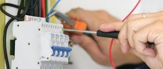
When performing any electrical work, as well as during the final inspection, it is necessary to follow safety rules: use rubber gloves and shoes, do not work alone
One of these methods is to connect an ordinary incandescent lamp with a power of at least 100 W with one end to ground and the other to phase.
If the installation is done correctly, the lamp will burn as brightly as from a socket. Dim light or its complete absence is a reason to check the build quality.
Mechanism of action of the ground loop
Let's analyze the situation when there is no ground loop, and there is no RCD in the garage distribution network. The insulating layer of the phase inside the welding machine is broken, which is why a phase potential has arisen on its body.
Since the transformer neutral at the substation from which the power is supplied is grounded (that is, combined with a ground loop), the potential difference between the soil and the body of the welding machine is 220 Volts. Shoes do not act as an insulator, as they allow current to pass through. As soon as you touch the body, the person becomes energized. The amount of current passing through the body at a voltage of 220 Volts will be at least 15 mA. This means that the muscles will contract to such an extent that the person will not be able to unclench his hand and, if no one comes to the rescue at this moment, death will occur.
Now let’s imagine a situation where there is a grounding loop and damage to the insulating material of the phase wire has occurred. In this case, the protective mechanism is gradually activated. First comes the protective shutdown stage: when the garage and substation circuits are connected to each other, a short circuit current flows through the phase, and the machine turns off the equipment for a while. Even if a person touches a live body, the period of contact will be too short and significant harm to health will not be caused.
If there is no connection between the circuits and if this connection does not allow the generation of the current necessary to connect the protection, a protective connection device will be needed. The RCD will protect the outgoing lines. With this approach, the protective shutdown will not be triggered by a short circuit, but by a leakage current into the soil through the garage ground loop. As soon as the RCD detects a leak, it will immediately turn off the network. Thus, a person standing on the ground will be safe.
The body resistance between the area where there is voltage and the lower limbs is hundreds of kOhms. The resistance of the conductor between the housing and the ground loop is much less than one ohm, and the resistance of the loop itself is not higher than several tens of ohms. As a result, there are two resistances connected in parallel - the body and the ground electrode. Most electricity follows the path of least resistance (to the ground loop). A person will receive a small amount of current, not exceeding the release threshold.
Grounding systems
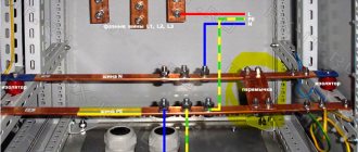
If there is a solidly grounded neutral, there are three options for connection systems for working and grounding conductors. The working ones include zeros (the load current flows through them). Protective conductors are used exclusively to transport the earth potential from the ground electrodes to the consumer. There are several options for how to make protective grounding. The choice is between TN-C, TN-S, TN-CS and TT systems.
TN-C protection
This standard was generally accepted more than ten years ago. The system is easy to recognize by the number of conductors in the power cable: there are always two of them. One is phase, the other is combined null (PEN). This name (combined) is due to two functions of the conductor: the operating current passes through it and a connection is made to the ground loop of the power cable.
With this approach, the neutral conductor cannot be used as a grounding conductor. Otherwise, when connecting to the grounding contacts of sockets, there is a high probability of unexpectedly being energized. A break in the PEN conductor will lead to this result, which is very likely in old electrical networks, since the contacts in them are usually in extremely poor condition. Due to the redistribution of currents across phases, a potential in the range from 0 to 220 Volts will appear in the neutral conductor, and all grounding socket contacts will be energized. Since the contacts will be energized, the same will happen with the housings of electrical household appliances.
When it comes to a garage, you don’t even need a zero break to get potential on the PEN conductor. The electrical wiring has a small cross-section, and the distance to the substation is large. Surely many have noticed that when working with a welding machine in neighboring garages, the light not only flickers or dims, but also periodically becomes brighter - this is a consequence of increased wiring resistance. At such a moment, potential arises at zero.
TN-S protection
Three-core power cables and a pair of neutral buses are signs of the TN-S grounding system. Here the tasks of the protective and neutral conductors are separated. Whatever the load on the garage network, whenever there are breaks in the zero working conductors on the protection, a dangerous potential will not arise.
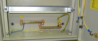
If the garage is located near the substation and the protective conductor starts there, there is no need to make a circuit. However, if there is a significant distance to the substation, you cannot do without a circuit. The output from the garage circuit is connected to the protective conductor bus in the switchboard.
TN-CS protection
This device is a transition from TN-C to the more advanced TN-S. The combined zero diverges into protective and working. A repeated grounding loop is organized at the separation section. In the future, three wires go to consumers (according to the TN-S system).
Creating such a contour with your own hands will not be a problem. However, one should take into account the nuance associated with the same potential danger of breaking the combined zero. If, when a dangerous potential occurs on a conductor, the current flowing through the circuit causes a reaction from the input circuit breaker, the system must ensure safety. Otherwise, it is recommended to additionally protect the group lines with a residual current device.
TT protection
The system is analogous to TN-C, but there is a difference in that there is no connection of the ground loop to the PEN conductor. The circuit is left independent; it is connected only to housings, metal surfaces, and grounding socket contacts. The taps from the electrical panel are always protected by a residual current device for currents above 30 mA.
The disadvantage of the scheme is that it is ineffective in case of damage to the cable if current enters the metal structures of the garage.
Lightning rods
An object with a grounding loop, according to the PUE, must be equipped with a lightning rod. Especially if we are talking about a dacha, where residents dig wells, drill wells for water and lay pipes very shallowly, or even run them on top. Buildings on summer cottages are often built from flammable materials, and firefighters are far away. Plus, a possible thunderstorm will most likely be accompanied by increased wind.
There are known cases when, in bad weather, entire holiday villages burned out from lightning strikes. As a rule, the culprits of the disaster were found quickly - in fires, a section was always found where there was a grounding loop, but there were no remnants of a lightning rod.
Meanwhile, the simplest lightning rod is a pair of pointed reinforcements protruding 1.2-1.5 m above the roof ridge. They are connected to the ground loop by a steel wire with a cross-section of at least 6 mm or a steel bus 15 x 3 mm.
The width of such a lightning rod cannot be more than 60 mm, otherwise the impact may cause plasma splashing, the consequences of which are simply destructive. A structure that is too wide will definitely act as an antenna: it will not deflect lightning into the ground, but will scatter it to the sides.
Important
The parts of the lightning rod must be exclusively welded, and the edges of the bus (if this is the one used) must be welded, including all layers (welding step 50-60 cm).
Creating Grounding
Before making a grounding loop with your own hands, it is recommended to pay attention to a number of important circumstances:
- Particular attention should be paid to contacts. Twists are prohibited. Truly reliable connections allow you to create terminals.
- The residual current device guarantees the safety of electrical wiring even in the event of current leaks. In the event of an emergency, the RCD immediately turns off the power.
- The best material for making electrodes is steel angles. The recommended corner size is 50 by 50 millimeters. The optimal length of the corner is from 2 to 2.5 meters. Some garage owners use pipes instead of a corner. This option is acceptable, but the thickness of the pipe walls must exceed 3.5 millimeters. The recommended pipe diameter is more than 32 millimeters.
- The ground loop configuration is important. Many people choose a triangular design, but experts insist that the T-shape design is more effective. In this case, one pair of electrodes is installed in the corners in the front part of the garage, the other pair is mounted in the inspection hole. All electrodes are combined with each other and then connected to the bus in the electrical panel.
- It is recommended to use a flexible wire to connect the underground part of the system to the grounding bus. The best choice is a copper cable with a six-millimeter cross-section. Aluminum cable requires a sixteen-millimeter cross-section.
Existing ground loop configurations are shown in the figure below.
Connection instructions
- The protective circuit device (RCD) must be connected to the panel. In case of emergency, the RCD turns off the power at the input itself.
- The grounding circuit for a metal garage is made in the form of a triangle or in a straight line. The T system involves the placement of several electrodes in front of the garage, as well as two buried in the inspection hole. Next, the electrodes are connected to each other and connected to the shield.
- Metal corners about two meters long are used as electrodes. The diameter of the metal pipes for work should be approximately three and a half centimeters, the wall thickness should be about four millimeters.
- To connect the entire structure you will need a flexible wire. Usually copper or aluminum wire is used.
Vertical ground electrode
In most cases, to create a vertical circuit, vertical grounding devices are chosen using (optional) corners, pipes or copper conductor. Below is a standard diagram for organizing grounding in a garage.
To install the ground loop, dig a hole in advance. Its depth should be approximately half a meter.
Vertical grounding devices must not be dug into the ground. Only driving in is allowed. A certain distance should be maintained between the electrodes (from one and a half to two meters). The electrodes are driven into the ground using a sledgehammer. The device must completely penetrate the ground and even go about 50 centimeters deep.
The installed electrodes are connected to each other with a metal tape or rod. The recommended tape cross-section is from 100 square millimeters. The diameter of the rod must exceed 10 millimeters.
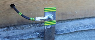
Connections are made using a welding machine. All seams must be painted to protect the metal from corrosive processes.
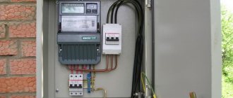
The final part of the work is laying a three-core cable that extends from the electrical panel. The cable is connected to sockets and lighting equipment.
How to properly connect with your own hands
When grounding the garage wiring yourself, it is better to use the TT system, which is the easiest to do. The work is carried out in several stages:
- Digging holes and trenches. To dig the electrode corner into the ground near the garage, a hole about 50-55 centimeters deep is made. Between each recess, a trench is dug in which the reinforcement will be laid.
- Installation of electrodes. When digging electrodes into the ground, take into account that the distance between them should be about one and a half meters. To make the corners fit better into the ground, their ends are ground with a grinder and made sharper. When installing conductors, you can use a sledgehammer or hammer.
- Installation of connectors. The dug-in elements are connected by iron strips made from profiles. Metal sheets with a thickness of five millimeters or more are used as connectors. They are connected to the electrodes with a welding machine.
- Pulling the wire. At the end of creating the grounding loop, the wire from the distribution board is brought to the garage, after which it is connected to the sockets.
Horizontal ground electrode
This scheme involves laying a metal strip on the surface of the trench. A bolt is welded to the tape, to which the cable (made of copper or aluminum) is directed. The second end of the wire is connected to the PE bus (located in the switchboard). The process is completed by burying the trench with loose soil. The soil used must not contain large stones or construction waste.
The figure below shows a diagram of the functioning of horizontal grounding.
System check
Regardless of the chosen grounding arrangement, after completion of work it is necessary to test the created system for operability.
For this purpose, it is recommended to invite a professional electrician with special equipment. A test result of over 47 ohms indicates the need to install several more electrodes.
The described schemes are relevant for garages located at a distance from residential buildings. If the garage is located next to a private house equipped with a grounding loop, the situation is fundamentally different. It is enough to pull a three-wire cable from the switchboard to the garage building.
Instructions
Initially, holes are dug, about half a meter deep. Trenches are made between them for the location of grounding reinforcement. The electrodes should be placed at a distance of approximately one meter, maybe a little more. Next, drive the corners into the ground. Now you need to drive in the electrodes using a heavy hammer. Each electrode is driven in such a way that about fifty centimeters of soil remains above it.
The corners are connected using a strip of metal with a thickness of at least five millimeters. Having welded the elements using a welding machine, they are connected to each other. Then connect the wires to the corners using terminals.
Upon completion of all work, all that remains is to stretch the three-core cable to the panel from the room. It is this cable that is used to connect to all electrical appliances; it is grounded.
Whether grounding is necessary in the garage, of course, its owner must decide, but it is better to do this in advance, without waiting for unpleasant consequences. It is worth paying attention to the fact that you cannot joke with electric current.
If the garage is located on the territory near the place of residence, then it is not necessary to have a grounding device in the garage. After all, the grounding system is located in the house. In this case, a three-core cable is run from the house to the garage.