To maintain an electric current in a conductor for a long time, it is necessary that the charges delivered by the current are constantly removed from the end of the conductor, which has a lower potential (consider that current carriers are assumed to be positive charges), while charges are constantly supplied to the end with a higher potential. That is, it is necessary to ensure the circulation of charges. In this cycle, charges must move along a closed path. The movement of current carriers is realized using forces of non-electrostatic origin. Such forces are called third parties. It turns out that to maintain the current, external forces are needed that act along the entire length of the circuit or in individual sections of the circuit.
Ideal EMF source
We have an EMF source
Let's remember what EMF is. EMF is something that creates an electric current. If we connect any load to such a voltage source (even a billion halogen lamps connected in parallel), it will still produce the same voltage as it would have produced if we had not connected any load at all.
Or simpler:
In short, no matter how much current passes through the resistor circuit, the voltage at the ends of the EMF source will always be the same. Such an EMF source is called an ideal EMF source .
But as you know, nothing is ideal in our world. That is, if our battery had an ideal source of EMF, then the voltage at the battery terminals would never sag. But it sags, and the more, the more current the load consumes. Something is wrong here. But why does this happen?
Third party force
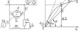
Nevertheless, current flows through the circuit; therefore, there is a force that “pulls” the charge through the source despite the resistance of the electric field of the terminals (Fig. 1).
Rice. 1. Third party force
This force is called a third party force
;
It is thanks to it that the current source functions. The external force has nothing to do with the stationary electric field - it is said to be of non-electrical
origin; in batteries, for example, it arises due to the occurrence of appropriate chemical reactions.
Let us denote by the work of an external force to move a positive charge q inside the current source from the negative terminal to the positive. This work is positive, since the direction of the external force coincides with the direction of charge movement. The work of an external force is also called the work of a current source
.
There is no external force in the external circuit, so the work done by the external force to move the charge in the external circuit is zero. Therefore, the work of an external force to move a charge around the entire circuit is reduced to the work of moving this charge only inside the current source. Thus, this is also the work of an external force to move charge throughout the circuit
.
We see that the external force is non-potential - its work when moving a charge along a closed path is not zero. It is this non-potentiality that allows the electric current to circulate; a potential electric field, as we said earlier, cannot support a constant current.
Experience shows that work is directly proportional to the charge being moved. Therefore, the ratio no longer depends on the charge and is a quantitative characteristic of the current source. This relationship is denoted by:
(1)
This quantity is called electromotive force
(EMF) of the current source. As you can see, EMF is measured in volts (V), so the name “electromotive force” is extremely unfortunate. But it has long been ingrained, so you have to come to terms with it.
When you see the inscription on the battery: “1.5 V”, then know that this is exactly the EMF. Is this value equal to the voltage created by the battery in the external circuit? It turns out not! Now we will understand why.
Internal resistance of the EMF source
The thing is that a resistance is “hidden” in the battery, which, relatively speaking, clings in series with the source of the battery’s emf. It is called internal resistance or output resistance. Indicated by a small letter “ r ”.
It all looks like this in the battery:
We hook the light bulb
So, what do we get in its pure form?
A light bulb is a load that has resistance. So, we simplify the diagram even more and get:
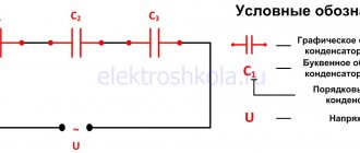
We have an ideal EMF source, internal resistance r and load resistance R. Recall the article voltage divider. It says that the voltage of the EMF source is equal to the sum of the voltage drops across each resistance.
The voltage UR drops across the resistor R, and the voltage Ur drops across the internal resistor r.
Now let's remember the article current divider. The current flowing through series-connected resistances is the same everywhere.
Let's remember algebra for 5th grade and write down everything that we just talked about. From Ohm's law for a section of the chain we obtain that
Further
Lenz's rule
To determine the direction of the induced current, you need to use Lenz's rule.
Academically, this rule is as follows: the induced current excited in a closed loop when the magnetic flux changes is always directed in such a way that the magnetic field it creates prevents the change in the magnetic flux causing the induced current.
Let's try a little simpler: the coil in this case is a dissatisfied granny. They take away her magnetic flux - she is unhappy and creates a magnetic field, which this magnetic flux wants to take back.
They give her a magnetic flux, take it, they say, use it, and she’s like, “Why did I give up your magnetic flux!” and creates a magnetic field, which expels this magnetic flux.
Voltage sag
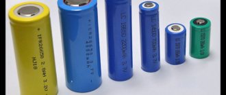
So, meet the car battery!
For further use, solder two wires to it: red to positive, black to negative
Our ward is ready for battle.
Now we take a car halogen light bulb and also solder two wires with alligators to it. I soldered the low beam to the terminals.
First of all, let's measure the voltage at the battery terminals
12.09 volts. This is quite normal, since our battery produces exactly 12 volts. Let me jump ahead a little and say that now we have measured the EMF.
We connect the halogen lamp to the battery and measure the voltage again:
Have you seen it? The voltage at the battery terminals dropped to 11.79 Volts!
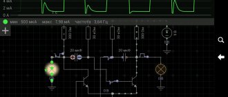
Let's measure how much current our lamp consumes in Amperes. To do this, we create the following diagram:
The yellow multimeter will measure voltage, and the red multimeter will measure current. You can read how to measure current and voltage using a multimeter in this article.
Let's look at the instrument readings:
As we can see, our lamp consumes 4.35 Amperes. The voltage dropped to 11.79 Volts.
Let's replace the halogen lamp with a simple 12 Volt incandescent lamp from a motorcycle
Let's look at the readings:
The light bulb consumes a current of 0.69 Amps. The voltage dropped to 12 volts exactly.
What conclusions can be drawn? The more current the load consumes, the more the battery voltage drops.
Video
Coffee capsule Nescafe Dolce Gusto Cafe O Le Coffee with milk, 3 packs of 16 capsules each
1305 ₽ More details
Coffee capsules Nescafe Dolce Gusto Café Au Lait, 16 pcs.
435 ₽ More details
Samsung Galaxy smartphones
How to find the internal resistance of an EMF source
Let's go back to this photo again
Since in this case the circuit is open (there is no external load), therefore the current in circuit I is equal to zero. This means that the voltage drop across the internal resistor Ur will also be zero. As a result, we are left with only the EMF source, from which we measure the voltage. In our case, EMF = 12.09 Volts.
As soon as we connected the load, the voltage immediately dropped across the internal resistance and the load, in this case the light bulb:
Now at the load (on a halogen) the voltage drops UR = 11.79 Volts, therefore, at the internal resistance the voltage drop is Ur = E-UR = 12.09-11.79 = 0.3 Volts. The current strength in the circuit is equal to I = 4.35 Amperes. As I already said, our EMF is equal to E = 12.09 Volts. Therefore, from Ohm’s law for a complete circuit we calculate what our internal resistance r will be equal to
From electrostatics to electrokinetics
Between the end of the 18th and the beginning of the 19th century, the work of scientists such as Coulomb, Lagrange and Poisson laid the mathematical foundations for the determination of electrostatic quantities. Progress in the understanding of electricity at this historical stage is obvious. Franklin had already introduced the concept of “amount of electrical substance,” but so far neither he nor his successors have been able to measure it.
Following Galvani's experiments, Volta tried to find evidence that the animal's "galvanic fluids" were of the same nature as static electricity. In his search for truth, he discovered that when two electrodes of different metals come into contact through an electrolyte, both become charged and remain charged despite the circuit being closed by the load. This phenomenon did not correspond to existing ideas about electricity because electrostatic charges in such a case had to recombine.
Volta introduced a new definition of the force acting in the direction of separating charges and maintaining them in this state. He called it electromotive. Such an explanation for the description of battery operation did not fit into the theoretical foundations of physics at that time. In the Coulomb paradigm of the first third of the 19th century. d.s. Volta was determined by the ability of some bodies to generate electricity in others.
Ohm made the most important contribution to the explanation of the operation of electrical circuits. The results of a series of experiments led him to the construction of the theory of electrical conductivity. He introduced the quantity “voltage” and defined it as the potential difference across the contacts. Like Fourier, who in his theory distinguished between the amount of heat and temperature in heat transfer, Ohm created a model by analogy relating the amount of charge transferred, voltage and electrical conductivity. Ohm's law did not contradict the accumulated knowledge of electrostatic electricity.
You may be interested in Formula for determining the electric field strength
Then, thanks to Maxwell and Faraday, explanatory models of current received a new field theory. This allowed the development of a field-related energy concept for both static potentials and electromotive force. The main dates for the evolution of the concept of EMF:
- 1800 - creation of the Voltaic galvanic battery;
- 1826 - Ohm formulates his law for a complete chain;
- 1831 - discovery of electromagnetic induction by Faraday.
Conclusion
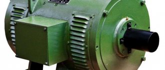
Internal resistance occurs not only in various chemical voltage sources. Various measuring instruments also have internal resistance. These are mainly voltmeters and oscilloscopes.
The point is that if we connect a load R, the resistance of which is less than or even equal to r, then the voltage will drop very significantly. This can be seen if you short-circuit the battery terminals with a thick copper wire and measure the voltage at the terminals at this time. But I do not recommend doing this under any circumstances! Therefore, the higher the resistance of the load (that is, the higher the load resistance R), the less influence this load has on the source of electrical energy.
When measuring voltage, a voltmeter and an oscilloscope also slightly drain the voltage of the voltage source being measured, because they are loads with high resistance. This is why the most accurate voltmeter and oscilloscope have a very high resistance between their probes.
Magnetic flux
Before you understand what electromagnetic induction is, you need to define such an entity as magnetic flux.
Imagine that you took a hoop in your hands and went outside into the rain. The heavier the rain, the more water will pass through this hoop— the greater the flow of water .
If the hoop is positioned horizontally, a lot of water will pass through it. And if you start to turn it, it’s already smaller, because it is not located at a right angle to the vertical.
Now let's place the hoop vertically - not a single drop will pass through it (unless the wind blows, of course).
Magnetic flux is essentially the same flow of water through a hoop, only we count the magnitude of the magnetic field passed through the area, not the rain.
Magnetic flux through the area S of the circuit is a scalar physical quantity equal to the product of the magnitude of the magnetic induction vector B, the surface area S penetrated by this flux, and the cosine of the angle α between the direction of the magnetic induction vector and the normal vector (perpendicular to plane of a given surface):
| Magnetic flux Ф - magnetic flux [Wb] B—magnetic induction [T] S - area of the penetrated surface [m^2] n — normal vector (perpendicular to the surface) [-] |
Magnetic flux can be visualized as a value proportional to the number of magnetic lines passing through a given area.
Depending on the angle α, the magnetic flux can be positive (α < 90°) or negative (α > 90°). If α = 90°, then the magnetic flux is 0. This depends on the magnitude of the cosine of the angle.
You can change the magnetic flux by changing the area of the circuit, the field induction module, or the location of the circuit in the magnetic field (by rotating it).
In the case of a non-uniform magnetic field and a non-flat contour, the magnetic flux is found as the sum of the magnetic fluxes penetrating the area of each of the sections into which a given surface can be divided.