Electrical machines › DC electric machines
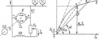
During operation of the DC generator, an emf Ea is induced in the armature winding. When a load is connected to a generator, a current arises in the armature circuit, and a voltage is established at the generator terminals, determined by the voltage equation for the generator armature circuit:
. (28.1)
Here
(28.2)
the sum of the resistances of all sections of the armature circuit: the armature winding ra, the winding of the additional poles rD, the compensation winding rc.o., the series excitation winding and the transition brush contact rsh.
If the machine does not have any of the indicated windings, (28.2) does not include the corresponding terms.
The generator armature is rotated by a drive motor, which creates a torque M1 on the generator shaft. If there is no load connected to the generator (operating in idle mode Ia = 0), then a relatively small idle torque M0 is needed to rotate its armature. This moment is due to the braking moments that arise in the generator when it operates in idle mode: moments from friction forces and eddy currents in the armature.
When the generator operates with a connected load, a current appears in the wires of the armature winding, which, interacting with the magnetic excitation field, creates an electromagnetic torque M
.
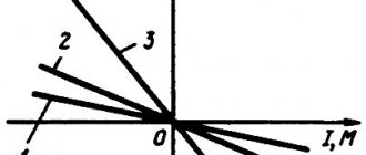
In the generator, this moment is directed counter to the torque of the PD
(Fig. 28.1), i.e. it is load (braking).
Rice. 28.1. Torques acting in a DC generator
At a constant rotation speed n = const, the torque of the drive motor M1 is balanced by the sum of counteracting moments: torque x.x. M0 and electromagnetic moment M,
i.e.
. (28.3)
Expression (28.3) is called the torque equation for a generator at a constant load frequency. Multiplying the terms of equation (28.3) by the angular velocity of rotation of the armature ω , we obtain the power equation:
,
(28.4)
where P1 = M1 ω
— power supplied from the drive motor to the generator (mechanical); P0 = M0ω no load power, i.e. power supplied to the generator in no mode. (with the load off); PEM = Mω—electromagnetic power of the generator.
According to (25.27), we get
,
or taking into account (28.1)
, (28.5)
where P2
— useful power of the generator (electric), i.e. the power supplied by the generator to the load;
Pеa
is the power loss due to heating of the windings and brush contact in the armature circuit.
Taking into account the excitation losses of the REV generator, we obtain the power equation for the DC generator:
. (28.6)
Therefore, the mechanical power developed by the drive motor P1
,
is converted in the generator into useful electrical power P2
transferred
to the load, and power
.
Since generators usually operate at a constant speed, their characteristics are considered under the condition n = const.
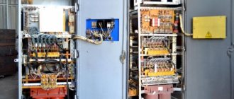
Generator design
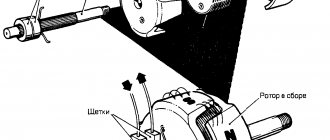
Let's look at what a DC generator is. Firstly, this is the device body made of durable steel or cast iron. The magnetic field created by the poles of the generator also passes through the body. Secondly, these are the rotor and stator.
An excitation coil is attached to the ferromagnetic stator. The direction of the magnetic flux is determined by the stator cores equipped with poles.
For high efficiency of the generator itself, the rotor is assembled from metal plates. In addition, this rotor design can significantly reduce the occurrence of eddy currents.
A copper or copper-plated winding is wound onto the metal plates of the core - a self-excitation winding. The number of generator brushes made of graphite depends on the number of poles on it, at least two. We can clearly see the design of the generator in the figure.
The output of the generator circuit is connected using collector plates. The plates are made from an affordable and good conductor of electric current - copper, and are separated from each other by a dielectric.
Voltage equation
The voltage equation U at the generator terminals has the form
| U = Ea – Ia × rа – 2 × ΔUш | (11) |
Where
| Ea = ce × Фδ × n | (12) |
represents e. d.s. armature, rа is the resistance of all series-connected windings of the armature circuit, and 2 × ΔUш is the voltage drop in the contact layer of brushes of both polarities.
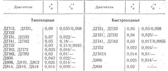
Usually, to simplify calculations, a constant resistance of the brush contacts is introduced
| Rsh = 2 × ΔUsh / Ian | (13) |
and instead of expression (11) they use the equation
| (14) |
Where
| Ra = ra + Rsh | (15) |
– total resistance of the armature.
Due to the variability of the contact resistance of the brushes, equation (14) is somewhat approximate, but the error is insignificant. For carbon and graphite brushes, take 2 × ΔUsh = 2 V and for metal-graphite brushes 2 × ΔUsh = 0.6 V. In generator mode, U is always less than Ea.
Operating principle
The principle of operation of a direct current generator, like any other device of a similar type, is based on the phenomenon of electromagnetic induction, familiar to us from school, and the appearance of electromotive force in the device - EMF. Let's remember school physics: if you attach any load to a conductor with a permanent magnet rotating inside it, then an alternating current will appear in it. This is possible due to the fact that the magnetic poles of the magnet itself have swapped places.
To obtain a constant current, it is necessary to connect the load connection points synchronously with the rotation speed of the magnet. This is what the generator's commutator is designed for, mounted on the rotor and rotating at the same frequency.
The energy obtained as a result of this entire process is removed using graphite brushes, which have good conductivity and fairly low friction. When the collector plates are switched, the EMF is zero, but its polarity does not change due to reconnection to another conductor.
Torque equation
If all terms of equation (2) are divided by the angular velocity of rotation of the armature
Ω = 2 × π × n
then we obtain the torque equation for steady-state operation:
| (3) |
Here
| (4) |
represents the torque of the prime mover applied to the shaft,
| (5) |
– electromagnetic torque developed by the armature, and
| (6) |
– braking torque corresponding to friction losses (Mtr) and magnetic and additional losses (Ms.d), which are covered by mechanical power.
In unsteady mode, when the rotation speed changes, the so-called dynamic torque also occurs
| (7) |
where J is the moment of inertia of the rotating parts of the generator. Dynamic torque corresponds to a change in the kinetic energy of rotating masses. As the rotation speed increases, the torque Mdyn > 0 and, like the torque M0 + Mem, are braking. In this case, the kinetic energy of the rotating masses increases due to the operation of the prime mover. If the moment Mdyn < 0, it acts in the direction of rotation and is driving, maintaining rotation by reducing the kinetic energy of the rotating masses.
Thus, in the general case, for n ≠ const,
| (8) |
Moment
| Mst = M0 + Mem | (9) |
corresponding to static forces is called static moment. Therefore we can also write
| Mv = Mst + Mdin | (10) |
Classification
Generators are divided into classes based on the principle of how they are excited. There are two main types of classification of generators: self-excited and independently excited generators.
The first class is devices where the winding is powered directly from the armature. It can be divided into sequential, parallel and mixed excitation. The second class is divided into electromagnetic and magnetoelectric excitation.
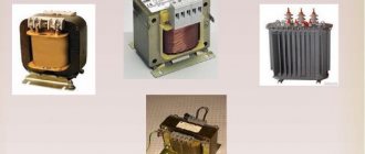
Photos of DC generators
1+
Read here! What is a Notarized Power of Attorney? Details