The probe is assembled on a piece of foil fiberglass and placed in a metal tube that acts as a screen. In order not to cause emergency situations when and if the probe falls on the switched-on device under test, the tube is covered with heat shrink. Without coating, the workpiece looks like this:
Disassembled probe:
Designs may vary. Just need to consider some things:
- If you perform a probe without a divider, i.e. it does not contain large resistances and switches, i.e. elements subject to electromagnetic interference, it is advisable to stretch the shielded probe wire all the way to the needle. In this case, you will not need additional shielding of the elements and the probe can be made from any dielectric. For example, use one of the tester probes.
- If the probe has a divider, then when you pick it up, you will inevitably increase interference and interference. Those. shielding of the divider elements will be required.
In my case, the connection of the tube to the screen (more precisely, to the back side of the fiberglass laminate) is made by soldering a spring onto the tectolite, which creates contact between the screen and the probe board.
As a needle I used a “Dad” from a ShR type connector. But it can be made from any other suitable rod. The connector from the ShR is convenient in that its “Mother” can be soldered into a clamp, which can be put on the probe if necessary.
Wire selection
The selection of wire deserves special mention. The correct wire looks like this:
The 3.5 mm minijack is located nearby for scale
The correct wire is a more or less ordinary shielded wire, with one significant difference - it has one central core. Very thin and made of steel wire, or even wire with high resistivity. I’ll explain why a little later.
This type of wire is not very common and is quite difficult to find. In principle, if you do not work with high frequencies of the order of ten megahertz, you may not feel much of a difference using a regular shielded wire. I have come across the opinion that at frequencies below 3-5 MHz the choice of wire is not critical. I can neither confirm nor deny - there is no practice at frequencies above 1 MHz. I will also tell you later in what cases this may have an effect.
Homemade oscilloscopes don't often have multi-megahertz bandwidth, so use whatever wire you can find. Just try to choose one with thinner central cores and fewer of them. I have come across the opinion that the central core should be thicker, but this is clearly part of the series of “bad advice”. Low resistance to the oscilloscope wire is unnecessary. There currents are in nanoamperes.
And it is important to understand that the lower the intrinsic capacity of the manufactured probe, the better. This is due to the fact that when you connect the probe to the device under test, you are thereby connecting additional capacitance.
If you connect directly to the output of a logical element or to a UPS, i.e. to a sufficiently powerful signal source that has a sufficiently low intrinsic resistance, then everything will be displayed normally. But if there is significant resistance in the circuit, then the probe capacitance will greatly distort the signal shape, because will charge through this resistance. This means that you will no longer be sure of the reliability of the oscillogram. Those. The lower the probe's intrinsic capacitance, the wider the range of possible uses for your oscilloscope.
How to burn $10,000 in one move and get electrocuted
Let's imagine a fairly ordinary situation: your mains power supply has broken down. You pick up a multimeter and measure the voltage at the input and output of the source. At the input you have an honest 230 V AC from the outlet, and at the output there are zeros. You know that your power supply is switching, and you are aware that the transistors of the source are controlled by a PWM controller, which is very easily identified on the board. You have a brand new Tektronix DPO 7254 oscilloscope or some LeCroy WavePro 7300A costing more than $10,000 on your desk, and you decide to use it to look at the PWM controller signals in order to diagnose its serviceability or malfunction. It is written on the oscilloscope probe that its maximum permissible voltage is 1000 V, which is by a good margin greater than the voltage in the outlet. Directly on the oscilloscope itself, next to the connectors for connecting the probes, the number 400 V is written, in addition, you have a probe with a divider of 1:100, which also gives you confidence that everything will be fine. You turn on the oscilloscope and try to connect its probe to the power supply board, however, as soon as you touch the oscilloscope probe to the power supply board, a spark jumps and a loud bang is heard. The screen of your brand new oscilloscope goes blank, the oscilloscope itself does not respond to any buttons, and the room is filled with the characteristic smell of burnt electronics. What happened? Why did the oscilloscope burn out and how to avoid it? Read about all this under the cut.
Denial of responsibility
This article addresses issues related to mains voltage, which can pose a threat to human life and health, as well as the performance of devices. All information in this article is provided for informational purposes only. You use the information provided at your own risk. In no event shall the author be liable for any direct, indirect, special or other consequential damages resulting from any use of the information in this article.
Power supply structure
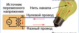
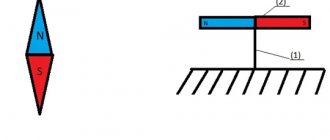
In this section, of course, we will not consider in detail the design of pulse converters; this is a topic for a whole series of articles. We will consider this issue to the minimum extent necessary to understand the topic of the article. So, the figure below shows essentially the block diagram of a simple flyback converter. The flyback converter is chosen here solely as an example; it doesn’t matter what topology the power supply is (forward, bridge, half-bridge, push-pull or even a ballast capacitor), everything said is true for any of them.
It does not show common-mode and differential-mode filters, protection circuits and some other components, but this is not necessary to consider our question. In the diagram we see a diode bridge to which mains voltage is supplied, a PWM controller chip combined with a power transistor, a transformer and a feedback circuit. The mains voltage is rectified by a diode bridge: the plus is supplied to the transformer and switched by a power transistor, and the minus forms the local (power) ground potential. The PWM controller is powered relative to this potential, the feedback voltage is measured, and control voltages are also applied relative to it to the gates of the power transistor (which in this circuit is located inside the controller). If we want to measure some voltage on the primary side, this must also be done relative to this potential. In general, this is a classic GND, with the exception of one nuance: it is not galvanically isolated from the network (it has a direct connection with the phase and neutral through a pair of diodes). And it is precisely this nuance that is decisive, but more on that later.
Oscilloscope structure
This section will consider the issue of galvanic coupling both between the oscilloscope channels themselves and between the oscilloscope channels and the ground line. There are two types of oscilloscopes: with isolated channels and without such isolation. Oscilloscopes with isolated channels are a rather rare type of device, and this fact will be emphasized in the description of the device. If you've never wondered whether your oscilloscope has this kind of isolation, it probably doesn't. What does this mean in practice? This means that the resistance between the ground tail of the oscilloscope probe and the ground pin in the 230 V power outlet is close to zero. For better understanding, this fact is demonstrated in the figure below.
This figure shows the resistance measurement between the ground tail of the oscilloscope probe and the ground pin of the oscilloscope power cord.
As you can see, the resistance value is very small and is only 2.18 Ohms. In reality, it is even less, because the resistance of the multimeter probes themselves, which can be more than 1 Ohm, was not taken into account. So, let's make an important conclusion: in an oscilloscope, the ground tail of the probe is connected to the ground contact of the socket and through it is grounded in the electrical panel.
Structure of a 230 V household network
The most complete description of the structure of a 230 V network, of course, is best found in some literature on the theory of electrical circuits, by reading the section on three-phase circuits.
Within the framework of this article, only a very small part of this course will be presented, which is directly related to our problem. A regular household outlet usually comes with 3 wires: phase, neutral and ground. In old Soviet-built houses there may not be a third wire (grounding). The ground wire is, in general, true to its name: it eventually goes into a bus (ground loop), which is buried deep in the ground somewhere under the building or in the immediate vicinity of it (of course, not just anyhow, but in accordance with certain rules). This wire is designed to protect a person from possible electric shock: in the event of an emergency, for example, voltage comes into contact with the device body, the current begins to flow through the grounding wire, which leads to the activation of the automatic protection system and the voltage being cut off.
Neutral is essentially very close to grounding. If you look closely at a power line in a rural area, you will notice that the neutral conductor is grounded at each pole.
In addition, the neutral conductor is also grounded at the substation (there are some nuances here, but in everyday life this is usually the case; we do not consider circuits with an isolated neutral).
In an ideal world, the resistance between the ground wire and the neutral in the socket is zero, and they are at exactly the same potential. In the real world, the resistance of conductors makes its own adjustments, and between the neutral and grounding there is a resistance of the order of several tens of ohms. Let's remember this fact; it will be useful to us in the future.
The phase conductor is the “working” conductor itself, which forms a sinusoid relative to the neutral. The sine wave in a household outlet has an amplitude of about 325 V and fluctuates plus and minus relative to the neutral conductor. Thus, with a positive half-wave of a sine wave, the current flows from the phase conductor to the neutral one, and with a negative half-wave, on the contrary, the current flows from the neutral conductor to the phase one.
What happens when you connect an oscilloscope?
So, let’s summarize the conclusions from the previous sections of the article:
- In a network switching power supply, the local (power) ground circuit is connected to the neutral and phase through diodes.
- In an oscilloscope, the ground tail of the probe is connected inside it to the ground contact of the socket.
- The resistance between the neutral and grounding in the network is small and amounts to a few to tens of ohms.
- With a positive half-wave of a sinusoid, current flows from the phase conductor to the neutral one, and with a negative half-wave, from the neutral to the phase conductor.
In order to understand how currents will flow when connecting an oscilloscope to the primary side of a switching power supply, it is best to use simulation.
Recently I usually use LTSpice as a modeling environment, so we will conduct the analysis in it. We will model exclusively the input circuits of the converter: now there is no need to include a transformer and other wiring in the model, because they do not affect the topic of the article in any way. I even excluded the storage capacitor after the diode bridge from the model, so that the transient process during its charging would not distract from the subject of the simulation. First, let's see how the circuit behaves without a connected oscilloscope. The figure below shows the results of modeling such a circuit (picture clickable).
Resistance R1 in this case is the load resistance. I chose it to be 100 kOhm. You can take any other, in this case its size is not important. Resistance R2 is the resistance between neutral and conductor and ground. I chose it to be 10 ohms. The amplitude voltage between phase and neutral is 325 V, which corresponds to an effective voltage value of 230 V, the signal is shown in the green graph.
As can be seen from the current graphs, it nowhere exceeds a few milliamps and the entire system feels good.
What happens if you connect an oscilloscope to such a circuit? The result is shown in the figure below (the picture is clickable).
As you can see, resistor R3 with a resistance of 2 Ohms has been added to the model. This resistor matches the resistance between the ground tail of the oscilloscope probe and the ground pin of the oscilloscope's power cord. A little higher, we measured this parameter and obtained a value equal to about 2 ohms. This resistor is connected to the local power ground PGND: this is where you will most likely connect the oscilloscope ground if you want to make measurements on the primary side of the power supply. But how does the current behave in this case? And it grows to catastrophic levels. The current in our model is more than 25 A! In this case, the current is limited by the resistance between neutral and ground, the internal resistance of the diode bridge, as well as the resistance of all wires. And this current flows, among other things, through resistor R3, i.e. through the oscilloscope probe and through its internal circuits. 25 And through the internal circuits of the oscilloscope, they are guaranteed to burn out everything that is possible inside; it is not even a fact that the printed circuit board itself will survive. Thus, this picture very clearly shows what will happen to the device if you just try to measure signals on a source that is not disconnected from the network.
If we analyze the results above a little, it becomes clear that the negative half-wave of a sine wave in the socket is fatal for an oscilloscope. The negative half-wave creates a negative potential at the point between diodes D1 and D3. A zero potential (GND) is applied to the PGND point through the tail of the oscilloscope probe, which is connected inside it to the ground of the socket. Thus, we form a potential difference, and diode D1 turns on in direct polarity, which leads to a sharp increase in current. All of the above is clearly illustrated in the figure below.
What about the RCD?
Indeed, when the ground tail of the oscilloscope is connected to the local (power) ground, a current imbalance occurs on the mains voltage side and this must be handled by the RCD. Perhaps it will save the oscilloscope circuits from complete burnout, however, alas, the RCD does not operate instantly; its response time is tens of milliseconds. During this time, at least one half-wave of the mains voltage sinusoid will have time to slip through, which, if it does not completely burn out the device, will most likely still damage the sensitive input circuits of the oscilloscope. In addition, the RCD is not always present in the electrical panel. Therefore, although an RCD is certainly a useful component of electrical wiring, in this case it is unwise to rely on it to protect the device. But what if you still need to look at some signals from a device operating on a 230 V network? In fact, there are several ways this can be done relatively safely, more on that in the next section.
How to look at the signals on the mains voltage side and not burn the devices?
1. Use an oscilloscope with galvanically isolated channels.
In an oscilloscope with galvanically isolated channels, all channels are isolated both from each other and from ground. Thus, when connecting the device to the circuit, we will not have a circuit through which a short circuit and burnout of the circuit can occur. However, be extremely careful, even if you have an oscilloscope with isolated channels. Carefully study the documentation for your device and pay attention to the specific figures for the maximum permissible voltage relative to ground. If you analyze signals on the mains voltage side, then most likely you will need special high-voltage probes that allow you to carry out measurements at high potential. Using an oscilloscope with decoupled channels has one big drawback - price. Such oscilloscopes are noticeably more expensive than oscilloscopes with similar characteristics, the grounds of which channels are connected on a common chassis. In addition, the range of such oscilloscopes is quite meager compared to classic oscilloscopes, of course. Overall, if you have an isolated-channel oscilloscope and know how to use it, chances are you didn't learn much new from this article.
2. Use a differential probe
If you do not have an oscilloscope with galvanically isolated channels, but have a regular one, then you can isolate any of its channels using a special device called a differential probe. An example of such a device is shown in the figure below.
With this device it is possible to view signals on the mains voltage side relatively safely. There are quite a large number of types of similar devices for different input voltages and frequencies with different input voltage division ratios. As a rule, these are active devices that require additional power, for example, the device in the figure above requires a 9 V adapter. The price of such devices is usually also not very affordable and amounts to tens and sometimes hundreds of thousands of rubles (at the exchange rate at the time of writing).
3. Use an isolation transformer
A completely working way to protect the oscilloscope and at the same time view the signals on the mains voltage side is to use an isolating transformer with a transformation ratio of 1:1 (i.e., the voltage value at the output of the transformer is equal to the voltage value at its input). Through such a transformer it is necessary to connect the object of study (for example, the same power source we are analyzing). An explanatory picture with the simulation results is shown below (the picture is clickable).
As we can see, despite the fact that the grounded tail of the oscilloscope probe is connected to the circuit in exactly the same way, there are no prohibitive values on the current graphs. The current through the inside of the oscilloscope (through resistance R3) is zero, and the amplitude of the current of the power supply and load is several milliamps, as we had with the oscilloscope not connected. This happens because we now have the PGND ground galvanically isolated from the mains voltage. However, this does not mean at all that now everything is safe for humans: the output of the transformer is still 230 V of effective voltage, which can pose a mortal danger.
When using an isolation transformer, in addition to the transformation ratio, it is also necessary to look at such a parameter as the maximum permissible power. Obviously, the power consumed by your load should not exceed the maximum permissible power that the transformer is designed to handle. Thus, this method is unlikely to be suitable for analyzing installations of several kilowatts: the dimensions and weight of the required transformer will be too large.
4. Use a laboratory power supply
If your object of study is a switching power supply, then you can safely view its primary circuits by powering it not from a 230 V network, but through a laboratory DC power supply. There is always a transformer inside such a power source, thus galvanic isolation is achieved, and the oscilloscope can be safely connected to the circuit being analyzed. Since there is a rectifier at the input of the switching power supply, there is no big difference for its operation whether you supply a sinusoid or a constant voltage to the input. Of course, the value of this DC voltage must correspond to the rectified mains voltage with some tolerance. In our previous work, we used the B5-50 source as such a power source; it is shown in the figure below.
It doesn’t look very modern, but it can produce an output voltage of up to 300 V and is well suited for debugging circuits with a power of up to a couple of hundred watts.
An additional very big plus of using a laboratory power supply when debugging is that you can set the required current limit on the power supply. This way, even if the circuit is faulty, you won't have a loud bang and most likely nothing will burn out. This approach is incomparably better than the well-known connection of a circuit through an incandescent light bulb. The only thing worth remembering is that the power of the laboratory power supply must be sufficient to power the circuit under study.
5. Use an outlet without grounding
Attention! This method is classified as dangerous, so I cannot recommend using it.
However, to complete the picture, I must tell you about it, if only to inform about possible dangers. Moreover, it happens that it often turns out to be the only possible way to view the signal on the mains voltage side without using any special equipment such as an isolation transformer or an oscilloscope with isolated channels. This method involves plugging the oscilloscope into a socket without a ground terminal (see the figure below).
This destroys the current flow path, but this leads to one big problem.
Now the oscilloscope ground is at a deadly potential. This means that life-threatening voltage will be present on all BNC connectors of the oscilloscope, on the ground tails of all connected probes, and also, possibly, on the housings of all other devices plugged into the same socket (if the socket is still there are grounding contacts, but there is no grounding wire connected to it). And if now you just touch the coaxial connector on the oscilloscope body with one hand, and with the other, conditionally, grab the battery... well, you understand. It is completely unacceptable to use this method if you have an oscilloscope in a metal case. If you still use this method, then disconnect all unnecessary probes, as well as other wires (USB, RS-232, etc.), make sure that only one oscilloscope is plugged into the outlet, make all connections, configure all the knobs on the oscilloscope in advance, Make sure that you do not accidentally touch the BNC connectors and only then apply mains voltage. However, if all precautions are taken, this method generally works. Below the spoiler is an oscillogram of the voltage from the outlet, taken by me back in my student years using this very method. Since the mains voltage has a range that exceeds the number of cells on the oscillograph screen, the measurement took place through a resistive voltage divider of 1:5.
Socket voltage
6. Use a battery-powered oscilloscope
Some oscilloscopes can be powered by built-in rechargeable batteries. The power cord is not connected; therefore, the oscilloscope is not grounded. In essence, this method is a complete analogue of the previous one, only instead of an ungrounded socket, the oscilloscope is powered from the built-in battery. This method is absolutely as dangerous as the previous one: the same deadly potential will be present on all connectors of the oscilloscope, therefore all the safety measures described in the previous paragraph of the article are equally valid for this method.
7. Power the control chips with low voltage from a laboratory source
Sometimes there are situations when high mains voltage is not necessary for debugging. In this case, it is better to simply power the control circuits using a low-voltage laboratory power supply. The required voltage is always specified in the documentation for specific microcircuits (for example, in the case of studying a PWM controller, it usually does not exceed 20 V). In this case, the 230 V mains voltage is not supplied, of course, so it is absolutely safe to use an oscilloscope to examine the pulses at the controller output, the operation of the oscillator, the value of the reference voltages and other critical signals. Of course, without the presence of mains voltage it will not be possible to check everything, but a frankly dead controller can be diagnosed without problems.
General recommendations for working with mains voltage
1. When working with mains voltage, always follow safety precautions
Yes, this has already been written about everywhere a hundred times, but, nevertheless, for some reason, what not to do is often found out only through personal experience. You should not climb into live devices during operation; it is better to complete all connections before turning on the power. Don’t forget about storage capacitors: their discharge takes some time, which can tend to infinity (conditionally, of course), if the developer has not installed discharge resistors.
2. Read the instructions for your device
Of course, life is too short to read instructions, so they are usually only opened when something doesn't work or is broken. But if you work with mains voltage, it’s still worth looking in advance to see what the actual limit numbers are for your device. Negligence in this matter can be very costly.
3. Use inexpensive appliances
If you are researching mains voltage, then put aside your cool Tectronix DPO 7254, which costs several million, and take some Nantek DSO 5102 for a couple of tens of thousands of rubles. On the mains voltage side, you don't need gigasamples and fancy math, but if something goes wrong, the error won't cost that much.
4. If possible, always work with galvanic isolation from the mains
Due to non-compliance with this rule, a lot of electronics have already burned out in this world. In my practice, there was a case that cost me a laptop and a JTAG debugger. I was debugging one device and there seemed to be no signs of trouble. The device had a metal case and a neon light was installed on the case, which glowed from a 230 V network. The case, naturally, was grounded. The board itself with the microcontroller was powered from a separate isolated power source. And at one fine moment this light bulb made its way onto the body of the device. At this moment, a JTAG debugger was connected to the board, which was plugged into the laptop. The laptop, in turn, was plugged into a grounded outlet. Thus, the current flowed along the chain “neon light bulb - case - board - JTAG debugger - laptop - laptop power supply - grounding.” Of course, the laptop and programmer burned out beyond repair. This could have been avoided if a galvanically isolated JTAG debugger had been used. Well, of course, it’s also not worth using a top-end MacBook Pro as a work machine when debugging power electronics (see the previous paragraph).
Conclusion
The things described in the article may seem simple, obvious and on the surface. However, unfortunately, I personally have more than once seen oscilloscopes burn out for the stated reason, and not from green guys, but from developers who have been in the industry for many years. If this article allows you to protect at least one oscilloscope from this, then I will already consider that I wrote it not in vain.
Schematic diagrams of probes
Actually, the probe circuit that I used is extremely simple:
This is a divider by 10 for an oscilloscope with a 1 meg input impedance. It is better to make up several resistors connected in series. The switch simply closes the additional resistance directly. A tuning capacitor allows you to match the probe with a specific device.
Perhaps here is a more correct scheme that would be worth recommending:
It is clearly better in terms of permissible voltage, since the breakdown voltage of SMD resistors and capacitors is usually taken as 100 volts. I've come across claims that they can withstand 200-250 volts. Didn't check. But if you are examining fairly high-voltage circuits, you should use just such a circuit.
I have never done it, so I can’t give any recommendations for setting it up (selecting capacitors C2, C3, C4).
Schemes of homemade oscilloscopes on microcircuits
First, let's analyze a simple circuit of an oscilloscope based on microns, which is assembled with only 3 transistors. To set up an amplifier or any other amateur radio device in which the circuit contains electrical oscillations, an oscilloscope is very convenient, with which you can observe the signal shape. Here is a description of an oscilloscope created from three transistors, two diodes and a cathode ray tube. The circuit diagram of an oscilloscope on a microscope is shown in image No. 1:
It’s not difficult to make amateur oscilloscopes, the circuits are quite understandable. Oscillo consists of a vertical beam deflection amplifier on transistor VT1, a scanning generator on transistor VT2 and a horizon amplifier. deviations on VT3. To eliminate distortion, the amplifier unit on VT1 is covered by negative feedback (through P4 and P6). From the reinforced type collector VT1, voltage is supplied through capacitor C2 to one of the beam vertical deflection plates.
The sweep generator unit on VT2 operates in avalanche mode. The frequency range of the master oscillator sweep device is divided into 4 subranges. Resistor P13 is needed to smoothly change the frequency within the sub-range. Synchronization of the frequency of the generator set is carried out by the frequency of the signal being studied, the voltage of which is supplied through C3 and P9 to the base circuit VT2, the synchronization level is controlled by resistor P11. From the output of the multiplier, the sawtooth voltage is transmitted through C11, P18 to the base of VT3, and from its collector through C12 to the horizon plate. beam deflection.
When the amplitude of the sawtooth voltage at the amplifier output is 70V, the length of the horizon. The line on the tube display is 50 mm. The brightness and focusing of the beam are regulated by variable resistor devices P23, P24, and the movement of the beam vertically and horizontally by resistor devices P10 and P15. Due to the low sensitivity of the oscilloscope, it should be supplemented with an amplifier, the circuit of which is shown in image No. 2:
The amplifier can be located either inside the housing or separately from it. When assembling the structure, the power transformer must be placed so that the axis of its coil is a continuation of the longitudinal axis of the tube. Also, the tube will need to be enclosed in a magnetic shield.
The assembled oscilloscope does not need to be configured, especially if it is USB. Sometimes the sweep generator does not begin to function immediately; in such a situation, it is necessary to change VT2. The auxiliary amplifier attachment is connected to the circuit break at point “A”, the amplifier input is connected to C1 and the output to the VT1 base. If the amplifier is implemented as a separate homemade block in an oscilloscope, then the divider for P1-P3 must be placed in the same block.
In the oscilloscope you can use transistors VT1, VT3 - KT502E, KT632B, MP26B, KT3157A; VT2 - KT3107, KT361, KT203B, V. Diodes VD1 and VD2 must be designed for a reverse type voltage of at least 700 V - D217, D218, KD203G and so on.
Now let's look at the second circuit, a standard pulse oscilloscope, which helps monitor signals in analog and digital devices.
The oscilloscope circuit shown to you is very similar to the previous one, but not in all respects. The basis of the unit is a 5LO38 CRT and a power source from the receiver. The vertical deflection channel is made on lamp H1. There are 2 vertical deflection inputs. Pulse or alternating voltage signals are transmitted to input X1. Input sensitivity is 0.5 volts per division. A variable resistor device P24 is needed for smooth sensitivity adjustment.
A little promised theory
Capacitance is directly proportional to the area of the conductors and inversely proportional to the distance between them. There is still a coefficient there, but for us it is not important now.
We have two conductors. Central core and wire screen. The distance between them is determined by the diameter of the wire. It is not possible to reduce the screen area much. No need to. It remains to reduce the SURFACE AREA OF THE CENTRAL VEIN.
Those. reduce its diameter as far as technically feasible without loss of mechanical strength.
Well, in order to increase this same strength while reducing the diameter, you need to choose a stronger material.
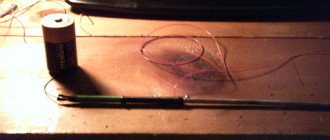
The wire can be represented like this:
Distributed capacitance along the length of the wire. Well, the greater the resistivity of the material of the central core, the less influence neighboring areas (adjacent containers) will have on each other. Therefore, a wire with high resistivity is advisable. For the same reason, it is not advisable to make the probe wire too long.
I won't look at the connectors. I’ll just say that I think BNC connectors are optimal for an oscilloscope. They are most often used. I would not recommend using a minijack or audio jack (although I use it myself, due to the fact that I do not use an oscilloscope in circuits with significant voltages). He's dangerous. The wire was pulled while testing circuits with good voltage. What happens next? And then the minijack, sliding along the socket, can cause a short circuit. And even if, for various reasons, nothing happened, this voltage will be present on the minijack itself. What if he falls into your lap? And there is an open central contact and ground nearby...
It's summer, it's hot, do you like to work in shorts? Choose BNC (no advertising). That's what's good about BNC. You can't just pull it out. And even if it happened, it is closed. Nothing dangerous should happen; what you wear will not be harmed))
Additional information can be gleaned from the series of articles Input nodes of homemade oscilloscopes. So, we got tired of the theory, now
Probe No. 2
The good thing about it is that it can be inserted like this:
Or like this, he doesn’t care, he spins freely.
It's structured something like this:
The only thing that will still be done on it. The hole for the ground wire to exit from the probe will be filled with a drop of hot-melt adhesive to make it more difficult to pull it out during an accidental tug, and the wire will be fixed in the handle with a piece of a match sharpened to a flat wedge.
So as not to break or unscrew the central core. By the way, this is the easiest way to “treat” cheap Chinese tester probes so that the wire does not break off from the tip.
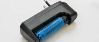
Beginner's oscilloscope DSO138 - instructions and upgrades
Any beginner involved in radio electronics sooner or later is faced with the need to find out the signal shape and frequency. This is why there are oscilloscopes, or “donkeys” in common parlance. Therefore, today I propose to consider an inexpensive Chinese version - dso138, just right for a beginner.
Link
Initially, this model was developed as a DIY soldering kit, but Chinese friends realized that in a soldered form the demand for an oscilloscope is higher. We will consider a ready-made, working board.
Despite the fact that sellers claim a maximum testable frequency of 200 kHz, you can hardly count on such a range. Well, just to estimate approximately the frequency, without a real picture of the signal shape.
If we are realistic, we should expect a relatively passable picture at a frequency of 50 kHz; higher, there will be severe distortion. This will be enough to set up various switching power supplies.
An important point is that this oscilloscope can and should even be made portable. A pocket device, even with such low characteristics, can be a very useful assistant in the repair of low-frequency components.
So, upon purchase you receive a box with a board and display, a probe in the form of two crocodiles and “short” instructions in English. You have to figure out how to use various functions using the “highly scientific poke” method and minimal information from the Internet.
Catering
Power supply requires a 9 V source; according to manufacturers, the supply voltage can be in the range of 8-12 volts. The current consumption is not indicated, looking ahead - it is just over 100 mA.
I consider it a very practical and universal solution to power the board from a portable battery (power bank) - now almost everyone has them. In addition, by adapting the oscilloscope for a 5 V battery, the board can be powered from a telephone charger.
To increase the voltage from 5 to 9 volts, you can use a DC-DC converter, for example MT3608
- costs a penny in a radio store or from the same Chinese. To connect to the board, I used a computer fan connector - those with two wires, for example from an old video card, are suitable.
Either because of the input capacitor, or for other reasons, the board has large starting currents and when the entire circuit is turned on, the internal battery protection is triggered (2 A output). The problem is easily solved by adding a 0.5 Ohm resistor across the input power supply of the DC converter.
Before connecting the oscilloscope board, you need to set the voltage on the converter to 9-10 volts, this is done by rotating the trimming resistor.
Before turning it on for the first time, I recommend soldering a jumper or pin for a reference signal; the place for the jumper is located next to the power connectors. The internal generator produces rectangular pulses with a frequency of 1 kHz and an amplitude of 3.3 V. To check, you need to touch the red crocodile to the jumper; the black crocodile does not need to be hooked anywhere.
Now you can turn on the entire circuit and begin to master the simple instructions.
Instructions for use
Purpose of buttons and switches
. The board has 3 switches: input switching, sensitivity and its multiplier. The input switches to 3 positions: ❶ “GND” - the input is shorted to ground and the screen displays only its own noise, you can judge the deviation from zero of the factory settings.
Ideally, the line should be at zero, but there are deviations at different sensitivities. ❷ “AC” - The input reacts only to alternating and pulsating currents; when a constant voltage is applied to the probe, the beam only twitches a little. It will not be possible to measure DC voltage.
❸"DC" - The input is connected without an isolation capacitor, therefore it responds to both alternating voltage and direct voltage. Can be used as a millivoltmeter.
Sensitivity 1V; 0.1V; 10mV; within small limits it is regulated by X1 multipliers; X2; X5; The product of sensitivity and multiplier is one vertical cell on the screen. This value is displayed on the screen.
There are 4 buttons to the right of the screen (1 at the bottom doesn’t count - it’s a reboot): pause/start - allows you to stop the changing picture and look at it in more detail, parameter selection - allows you to select one of several parameters and use the +- buttons to adjust.
Selectable parameters (according to the chronology of clicks): ❶ The horizontal duration of one cell, in fact, is adjusted to the desired frequency; ❷ Playback mode, I didn’t notice much difference between the three modes, only minor nuances, the “AUTO” mode is the most convenient; ❸ Trigger trigger, on the edge or fall of the signal.
I don’t really understand this function, it’s related to setting up devices with a digital, logical signal; ❹ Trigger cursor, you can set the desired voltage value to trigger. When the signal curve reaches the set value, the LED under the screen is activated.
In addition, when the cursor is within the current signal, the graph is more convenient to view; it does not float. For analog measurements it is better to set it to zero; ❺ Scroll the picture left/right.
The function is useful when pausing - you can view a signal curve of a longer duration than the screen allows; ❻ Zero cursor; in fact, it can be moved both up and down. In this way, positive or negative half-waves can be examined in more detail;
As for the parameters of the measured signal in the working area of the screen, let’s figure out what they mean: Freq
— the signal frequency itself;
Cycl
— period time;
Pw
—half-cycle time;
Duty
- duty cycle (Western analogue of duty cycle, 50% is equal to duty cycle 2);
Vmax
— Maximum amplitude value of the signal;
Vmin
— Minimum amplitude value (maximum negative);
Vavr
- Average voltage;
Vpp
- Value from Vmin to Vmax, if the swing is from -5 V to +5 V, then this value is 10 V;
Vrms
— Mean square voltage;
Zero setting
. When you turn it on for the first time, it is very noticeable that the zero cursor does not coincide with the signal line. This discrepancy manifests itself differently at different positions of sensitivity and multipliers.
To adjust the beam, you need to use the “Parameter Selection” button to select the zero cursor, and then hold down the “Pause/Start” button for 2 seconds. Similarly, the trigger cursor is set to the same level as zero.
If you don't need the signal values on the screen
— use the “Parameter Selection” button to select the sweep duration and press “Pause/Start” for 2 seconds. Identically, the inscriptions return to the screen.
The most important thing: do not forget that the maximum input voltage on the oscilloscope probes should not exceed 50 V. To measure higher voltages, you need to build an additional divider or take another probe with a built-in divider.
We will definitely look at a homemade divider and a housing for the described board, but later. Now let’s touch a little on the practical part, namely, what benefits can this “toy” bring?
Practical use
This device can be used perfectly as a voltmeter and millivoltmeter of both direct and alternating voltage. Moreover, we are no longer limited as much by the frequency or shape of the signal as when using a multimeter.
When taking measurements, you should pay more attention not to amplitude values, but to root-mean-square Vrms.
It is the rms value that is taken into account when measuring alternating voltage - in the network, the amplitude values reach more than 310 V, but the effective value is exactly 220 (rms).
Since we can measure voltage with fairly high accuracy, we can therefore more accurately measure any currents on the shunt; for this we just need to learn how to use Ohm’s law.
An oscilloscope can perfectly look at audio signals - for such purposes it is not a toy. If the quality is tolerable, you can watch processes in switching power supplies. I purchased this board specifically for these purposes.
As an example: an oscilloscope helped me set up a screwdriver power supply (there is a description in this section) with powerful IGBT transistors.
I couldn’t understand why the unit didn’t want to start, I rewound the commutating transformer with different data - nothing.
When I evaluated the signals on the gates, everything became clear - there is not enough opening voltage, we need to add turns in the gate windings. Here is this damped signal, quite clear, frequency 44 kHz:
This concludes the publication. If this topic is at all interesting to site visitors, I will definitely expand and supplement it. Give ratings and be active.
Rate this publication:
4.6 (103 )
See also other articles
Share: Facebook
- Previous postHow to make a manual jigsaw with your own hands
- Next entryDo-it-yourself modernization of a gas boiler
No comments yet
Probe circuit with divider and opto-isolator
Copy the diagram to enlarge on a PC
The second version of the high-voltage oscilloscope probe is based on OPA2340 . The author of the circuit indicates a maximum peak input voltage of 1000 V. Opto-isolation on the IL300 . The insulation voltage of IL300 is 5 kV. Power is supplied through the MC34063 converter from a 9 V battery.
- GRAPHIC VOLTAGE ANALYZER
- OSCILLOGRAPHIC SOUND CARD ADAPTER
- AC POWER DETECTOR