Magnetic field and its graphical representation
Stones that can attract objects made of iron were named after the island on which they were found - magnets. And their property of being located in space in a certain way formed the basis for the creation of a magnetic compass. Understanding how this device works is necessary for further study of the material.
So, the diagram of the simplest magnetic compass is shown in the figure. It consists of a thin needle on which is placed a small diamond-shaped magnet. This magnet can rotate freely on the needle.
As mentioned earlier, in the absence of external influence, magnets are always oriented in space in a certain way: with one end towards the North Pole of the Earth (by analogy, this end of the stone is called the north pole and is indicated in blue); and the other end towards the South (the south pole of the magnet is indicated in red).
Figure 1(a) – Magnetic needle (top view)
Figure 1(b) – Diagram of a simple compass
In 1820, Hans Christian Oersted gave a lecture in which he demonstrated the generation of heat on a current-carrying conductor: he passed current through a long conductor, as a result of which the conductor heated up. During a break between classes, curious students began to turn the installation on and off and accidentally noticed that when current passed through the conductor, a magnetic needle located nearby began to move. The students shared their observation with Oersted, who was very interested in this phenomenon and began to investigate it. The experiments he conducted were later called Oersted's experiments. They became the first evidence of the connection between electric current and magnetic properties.
Consider the experiment conducted by Oersted. A magnetic needle was placed under a long conductor connected to the circuit (see Figure 2).
Figure 2 – Scheme of the experiment of G.Kh. Oersted
When current begins to flow in the conductor, the magnet rotates to a position perpendicular to the conductor. Its direction depended on where the current was directed. Figure 3 shows a conductor carrying current, the direction of which is indicated by a white arrow. In this case, the magnetic needle was oriented with its blue end to the left.
Figure 3 – Magnetic needle oriented relative to the conductor
If in the installation in Figure 3 the poles of the source are swapped (the current will flow in the opposite direction), the arrow will turn the red end to the left.
That is, the current acts on the needle from the magnet. There is no direct contact between the needle and the conductor (they do not touch each other), which means that the action is carried out using a field*, which was later called magnetic.
It is important to note that the magnetic field:
- affects moving charged particles and substances that have magnetic properties;
- generated by moving charged particles or magnetic substances.
*Reminder: a field is a matter that cannot be seen or felt by the senses, but its effect on some objects can be detected.
Since the field cannot be seen or felt, but must be described and represented, it was decided to depict the magnetic field schematically - in the form of lines.
Magnetic field lines (also known as magnetic lines) are mentally drawn tangential lines towards which magnetic arrows would be oriented (these lines are imaginary; in reality, of course, they do not exist). They are a graphic representation of the magnetic field and are directed in the same direction as the north pole of the magnetic needle.
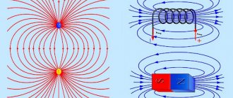
In Figure 4 you can see the field lines of a rectangular magnet. This type of magnet is often called strip magnet (from the word “strip”).
Figure 4 – Magnetic field lines of a rectangular magnet
Properties of magnetic lines:
- come out from the north pole of the magnet (i.e. start at it);
- enter into the southern one (end on it);
- are either closed or extending to infinity (starting at infinity).
Determination of magnetic field lines
If we turn to physics, magnetic field lines (MF) are straight lines to which tangents are drawn that have the same value as the orientation course of magnetic induction. Lines are drawn so that their frequency is commensurate with the magnetic induction values.
The higher they are at a certain point, the higher the frequency of the force lines.
This leads to the fact that the properties of field lines are similar to straight lines of electrostatics. However, the difference may lie in some features.
First you need to study the magnetic field that is created by a wire in direct communication with current. Let the conductive fiber run at right angles to the main plane. At different points that are at equal distances from the conductor, the induction values will be identical. A straight line, the tangent to which along its entire length corresponds to the path of the magnetic induction guide, will create a circle or oval.
According to the above, the straight lines of a direct-flow conductor under consideration are circles or ovals that envelop the conductor itself. It is in it that all the centers of force lines accumulate. They are completely different from electrostatic power lines. After all, the latter do not close, but originate and end in charges.
The field lines under consideration do not have end and start points. Today, the separately existing poles of magnets from the north and south, which can be taken as a source of a field of a certain polarity, have not yet been established. Also, they cannot be the beginning or end of power lines. However, all sources of magnetic fields are characterized by the presence of north and south poles.
Inhomogeneous and homogeneous magnetic field
If we return to the research of G.Kh. Oersted and observe the behavior of the arrow at various points, you can notice that the further the arrow is removed from the conductor, the less it deviates. This means that the field weakens with distance from the source.
What the magnetic field lines of a current-carrying conductor look like is shown in Figure 5. The reader is presented with a cross-section of a conductor with current flowing “into the drawing.” In this case, the field lines are concentric circles. Where the field is more intense (close to the source - conductor) the lines are drawn thicker, and in areas where it is weaker - less often.
Figure 5 – Magnetic field lines of a current-carrying conductor
A field that acts on a magnetic needle with the same force at different points in space is called uniform.
In the opposite situation, they speak of a non-uniform magnetic field.
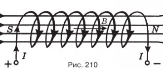
Strictly speaking, the magnetic field is almost always inhomogeneous. Nevertheless, the field created by some sources can be considered homogeneous in some small area. For example, the field in the area between magnets located in series (see Figure 6). The induction lines of a uniform magnetic field are parallel, and the density with which they are depicted does not change.
Figure 6 – Field between two magnets in series
Gimlet rule
The gimlet rule allows you to determine the direction of magnetic induction lines around a current-carrying conductor. If a gimlet (corkscrew) with a right-hand thread moves forward in the direction of the current, then the direction of rotation of the handle will coincide with the direction of the magnetic induction lines around the conductor (Figure 4).
A magnetic needle introduced into the magnetic field of a current-carrying conductor is located along the magnetic induction lines. Therefore, to determine its location, you can also use the “gimlet rule” (Figure 5). The magnetic field is one of the most important manifestations of electric current and cannot be obtained independently and separately from the current.
| Figure 4. Determining the direction of magnetic induction lines around a current-carrying conductor using the “gimlet rule” | Figure 5. Determining the direction of deviation of a magnetic needle brought to a conductor with current, according to the “gimlet rule” |
Direction of current and direction of magnetic field lines
Gimlet rule
Previously, a magnet arrow was used to determine the direction of the magnetic field in experiments. But what to do if you don’t have it at hand?
You need to know the rule of the gimlet* (right screw): when the translational movement of the gimlet (screw) is in the same direction as the current flowing in the conductor, the direction of rotation of the gimlet handle will indicate the direction of the magnetic field lines.
Figure 7 provides an illustration of how to use the gimlet rule. Relative to the reader, the current flows downward. The gimlet, located as in the figure, is rotated clockwise so that it moves down. Then, in accordance with the rule, the direction of the magnetic lines around the conductor is “clockwise”.
Figure 7 – Illustration of using the gimlet rule
*Reminder: In general, a gimlet is a cutting tool for drilling small holes. However, it is often difficult for schoolchildren to imagine it. A simpler example of a system similar to a gimlet is a regular stopper on a plastic bottle. When the bottle is positioned vertically and the cap is twisted clockwise, it moves progressively downward. If the plug is untwisted counterclockwise, it will move upward. You can use this example as a guide, mentally positioning the bottle with the stopper vertically or horizontally to make it easier to use the gimlet rule in the future.
Instead of a gimlet, the rule of the right hand is often used: if the thumb bent 90° from the palm is turned along the current in the conductor, and then the remaining fingers clasp the conductor, they will indicate the direction of the magnetic field lines.
An example explaining the right-hand rule is shown in Figure 8.
Figure 8 – Illustration of the application of the right hand rule
The gimlet rules and the right hand rules are equally convenient and you can use either of them. However, further we will also consider the left-hand rule. To avoid confusion about which situation to use which hand, it is preferable to use the gimlet rule to determine the direction of the magnetic field lines.
Magnetic lines of straight wire with current
We use the same experimental scheme for a straight wire through which electric current flows. In this case, you can replace the transparent plate with a piece of cardboard or plywood.
Rice. 3. Magnetic lines of a straight wire with current.
The sawdust can be seen to line up in concentric circles, showing the shape of the magnetic lines. When the direction of the current changes, the filings rotate by 1800. Consequently, the direction of the magnetic lines in this case is related to the direction of the current in the conductor.
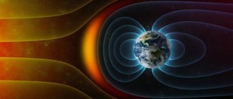
It is known that the Earth is a huge “strip” magnet. Thanks to this, with the help of a magnetic compass needle we can navigate in space. But we must keep in mind that there are places with large deposits of magnetites (iron ores), which create a strong “background” magnetic field, which turns the compass needle along its magnetic lines. One of these places is the Kursk magnetic anomaly, located in the Kursk region of our country.
Magnetic field magnitude
Magnetic field induction. Magnetic induction lines
In order to be able to characterize, describe and compare magnetic fields with each other, magnetic field induction or simply magnetic induction was introduced.
The SI unit of measurement for this quantity was chosen to be the tesla (T) - in honor of the famous scientist Nikola Tesla:
[B] = 1T
Magnetic induction is a vector. Its magnitude reflects the force with which the magnetic field acts on magnets or moving charged particles, and the direction indicates where the field lines are oriented.
A homogeneous field has a constant induction at all points. In a non-uniform field it changes.
To understand in more detail what this value is, we need to consider another experiment.
Consider a circuit consisting of a source, a switch K and a long conductor R (see Figure 9). If this conductor is surrounded by a uniform magnetic field (place it in a U-shaped magnet, for example) and the switch is closed, the conductor R will bend, because a force (F) will appear trying to push it out of the magnet.
Figure 9 – Conductor in a U-shaped magnet (1)
By changing the direction of the current in the magnetic field, you can notice that the force (F) will also begin to act in the opposite direction and will try to pull the conductor into the magnet (see Figure 10).
Figure 10 – Conductor in a U-shaped magnet (2)
In the same way, the force vector will reverse if the magnet is rotated 180°, while the direction of the electric current remains unchanged.
The force (F) that was discovered experimentally is called the Ampere force. With its help, the magnetic field acts on current-carrying conductors placed in it.
The direction in which the force acts is determined by the rule of the left hand: when the palm is turned so that the field induction vector enters it, and the four fingers are oriented towards the flow of current, the thumb bent by 90 indicates where the ampere force is directed.
A small disclaimer: a current-carrying conductor was previously considered. That is, charges were moving inside the conductor. It is logical that the magnetic field affects each moving charged particle separately.
The direction of current in a circuit is considered to be the direction of movement of positive charges. It turns out that, considering a separately flying positively charged particle, according to the left-hand rule, the fingers must be directed along the velocity vector of this particle. In the case of a particle with a negative charge, the fingers will need to be placed in the direction opposite to its speed (see Figure 10).
Figure 10 – Application of the left-hand rule for particles with charges of different signs
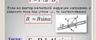
The Ampere's strength increases with increasing current, magnetic induction (B) and length of the conductor (L). In addition, there is a dependence on the orientation of the conductor in the field.
The Ampere force can be calculated using the formula:
(a is the angle between the direction of the current and the direction of the magnetic induction lines).
When the conductor is perpendicular to the lines of magnetic induction, the expression is rewritten as follows:
This expression is convenient for determining the magnitude of a uniform magnetic field. And the connection between units of measurement becomes obvious:
That is, an induction of 1 Tesla is the magnitude of a magnetic field that acts with a force of 1 Newton on a conductor having a length of 1 meter and a current strength of 1 ampere.
And now we can say that a more accurate name for magnetic lines is magnetic induction lines.
The direction of the magnetic induction lines is determined by the gimlet (right hand) rule.
| Examples of some magnetic fields | Field lines | Determining the direction of magnetic induction lines |
| Forward current field | Direct current magnetic induction lines are concentric circles lying in a plane perpendicular to the current. | The thumb of the right hand is directed along the current in the conductor, four fingers are clenched into a fist, the direction in which the fingers are bent coincides with the direction of the magnetic induction line. |
| Circular current field | The four fingers of the right hand are clenched into a fist, so that the direction in which the fingers are bent coincides with the direction of the current in the conductor, then the bent thumb will indicate the direction of the magnetic induction line. | |
| Solenoid field (coils with current) | The end of the solenoid from which the magnetic induction lines come out is its north magnetic pole, the other end into which the induction lines enter is its south magnetic pole. | It is determined similarly to the circular current field. |
A magnetic field is detected by its effect on current-carrying conductors or a moving charged particle.
| Ampere power | Lorentz force | |
| Definition | The force with which a magnetic field acts on a current-carrying conductor. | The force that a magnetic field exerts on a moving charged particle. |
| Formula | ||
| Direction | Left hand rule: if the left hand is positioned so that the magnetic induction lines enter the palm, the four extended fingers are directed along the current, then the thumb bent 90 degrees will indicate the direction of the Ampere force. | Left hand rule: if the hand is positioned so that the magnetic induction lines enter the palm, the four extended fingers are directed in the direction of movement of the positively charged particle, then the thumb bent 90 degrees will indicate the direction of the Lorentz force. |
| Work of force | ,where is the angle between the vectors and . | The Lorentz force does not do work on the particle and does not change its kinetic energy; it only bends the trajectory of the particle, giving it centripetal acceleration. |
The nature of the movement of charged particles in a magnetic field.
1) A particle with a charge enters a magnetic field so that the vector is parallel, in this case, the particle moves rectilinearly and uniformly.
2) A particle with a charge enters a magnetic field so that the vector is perpendicular, in this case the particle moves in a circle in a plane perpendicular to the induction lines.
3) A particle with a charge enters a magnetic field so that the vector makes a certain angle with the vector, in this case the particle moves in a spiral.
AN EXAMPLE OF SOLVING THE PROBLEM ON THE MOTION OF A CHARGED PARTICLE IN A MAGNETIC FIELD
An electron moves in a uniform magnetic field with induction 4. Find its period of revolution.
Answer: 8.9
From the formula obtained when solving the problem, it follows that the period of revolution of a charged particle in a magnetic field does not depend on the speed with which it flies into the magnetic field and does not depend on the radius of the circle along which it moves.
Content
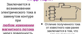
ELECTROMAGNETIC INDUCTION
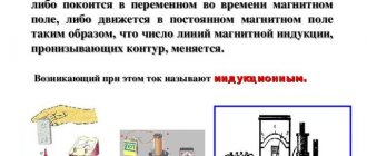
Electromagnetic induction is the phenomenon of the occurrence of induced emf in a conductive circuit located in a changing magnetic field. If the conductive circuit is closed, then an induced current arises in it.
LAW OF ELECTROMAGNETIC INDUCTION (FARADAY'S LAW): The induced emf is equal in magnitude to the rate of change of magnetic flux.
or , where is the number of turns in the circuit, magnetic flux.
The minus sign in the law reflects Lenz's rule: the induced current, with its magnetic flux, prevents a change in the magnetic flux that causes it .
, where is the surface area of the contour, the angle between the magnetic induction vector and the normal to the plane of the contour.
, where is the inductance of the conductor.
Inductance depends on the shape and size of the conductor (the inductance of a straight conductor is less than the inductance of the coil), and on the magnetic properties of the environment surrounding the conductor.
| Methods for obtaining induced emf | Formula | The nature of outside forces | Determining the direction of induction current |
| The conductor is in an alternating magnetic field | , Where | A vortex electric field that is generated by a changing magnetic field. | Algorithm: 1) Determine the direction of the external magnetic field. 2) Determine whether the magnetic flux is increasing or decreasing. 3) Determine the direction of the magnetic field of the induction current. If >0, then, if <0, then 4) Using the rule of the gimlet (right hand), determine the direction of the induction current. |
| The contour area changes | , Where | ||
| The position of the circuit in the magnetic field changes (the angle changes) | , Where | ||
| A conductor moves in a uniform magnetic field | , , where is the angle between | Lorentz force | Rule of the right hand: if the palm is positioned so that the vector of magnetic induction enters the palm, the outstretched thumb coincides with the direction of the conductor’s speed, then four outstretched fingers will indicate the direction of the induction current. |
| Self-induction is the phenomenon of the occurrence of induced emf in a conductor through which a changing current flows. | or | Vortex electric field | The self-induction current is directed in the same direction as the current created by the source, if the current strength decreases, the self-induction current is directed against the current created by the source, if the current strength increases. |
Example of using the algorithm:
When solving problems on electromagnetic induction, Ohm's law is used: , and .
MAGNETIC FIELD ENERGY
VORTEX AND POTENTIAL FIELDS
| Potential fields: gravitational, electrostatic | Vortex (non-potential) fields | ||
| magnetic | vortex electric | ||
| Field Source | Fixed electric charge | Moving charge (electric current) | Changing magnetic field |
| Field indicator (an object on which the field acts with some force) | Electric charge | Moving charge (electric current) | Electric charge |
| Field lines | Open lines of electric field strength begin on positive charges | Closed lines of magnetic induction | Closed lines of tension |
Properties of potential field forces (conservative forces):
1) The work of potential field forces does not depend on the shape of the trajectory, but is determined only by the initial and final position of the body.
2) The work done by the potential field forces when moving a body (charge) along a closed path is zero.
3) The work done by the potential field forces is equal to the change in the potential energy of the body (charge), taken with a minus sign.
Content
ELECTROMAGNETIC OSCILLATIONS
Electromagnetic oscillations are periodic changes in charge, current, and voltage.
— formula for calculating the period of electromagnetic oscillations (Thomson formula).
FREE ELECTROMAGNETIC OSCILLATIONS occur in an oscillatory circuit consisting of an inductive coil and a capacitor. In order for oscillations to occur in the circuit, the capacitor must be charged, giving it a charge.
| Charge |
| Current strength |
| Voltage |
| Electric field energy |
| Magnetic field energy |
| Total Energy |
An ideal oscillatory circuit is a circuit whose resistance is zero. In real circuits, therefore, the oscillations die out, the energy initially imparted to the circuit turns into heat.
FORCED ELECTROMAGNETIC OSCILLATIONS (ALTERNATING CURRENT)
Alternating current can be obtained by rotating a conducting frame in a magnetic field. In this case, the magnetic flux will change according to the law of sine or cosine.
Instantaneous value of induced emf in the circuit
where is the maximum value of the induced emf if the frame contains turns, then
The effective value of voltage and strength of alternating current is the voltage and strength of such a direct current at which the same amount of heat is released in the circuit as with a given alternating current.
Voltmeters and ammeters connected to an alternating current circuit measure effective values.
AC LOADS
| Load | Characteristic phenomenon | Current strength, voltage | Ohm's law |
| Active load | An irreversible conversion of electrical energy into heat occurs. | The current and voltage fluctuations are in phase. | active resistance. |
| Capacity | The capacitor is periodically charged and discharged. | Current fluctuations are ahead of voltage fluctuations by | capacitance. |
| Inductance | The self-induced emf prevents the current from changing in the coil. | Current fluctuations lag behind voltage fluctuations by | inductive reactance. |
RESONANCE IN AN ELECTRIC CIRCUIT is a sharp increase in the amplitude of fluctuations in current and voltage when the frequency of the alternating current supplied to the circuit coincides with the natural frequency of the circuit. Resonance is possible if a circuit containing inductance and capacitance and having a natural oscillation frequency , which depends only on and , is connected to an alternating current circuit with a frequency and Resonant frequency
At resonance
TRANSFORMER - a device that converts alternating current of one voltage into alternating current of another voltage without changing the frequency. Consists of primary and secondary coils mounted on a closed core. The primary coil contains the number of turns and is connected to the AC source, the secondary coil contains the number of turns and is connected to the electrical consumer.
Transformation ratio
By increasing the voltage several times, the transformer reduces the current by the same amount:
They increase the voltage and correspondingly decrease the current when transmitting energy from power plants to the consumer in order to reduce heat losses on the power line wires, then they obtain the voltage necessary for the consumer using step-down transformers.
Content
ELECTROMAGNETIC WAVES
An electromagnetic wave is an electromagnetic field propagating in space. The theory of electromagnetic waves was created by J. Maxwell in the 60s of the 19th century:
1) An alternating magnetic field generates an alternating electric field, an alternating electric field generates an alternating magnetic field, etc. This process lies in the formation of an electromagnetic wave.
2) The source of the electromagnetic wave is an oscillating (accelerating) charge.
3) An electromagnetic wave in a vacuum propagates at the speed of light
4) Electromagnetic waves are transverse. Oscillations of vectors and occur in mutually perpendicular planes, which are perpendicular to the direction of the speed of wave propagation, i.e. mutually perpendicular.
5) The oscillations of the vectors and coincide in phase, that is, they simultaneously turn to zero and simultaneously reach a maximum.
6) Electromagnetic waves can be reflected, refracted, they are characterized by the phenomena of interference, diffraction, dispersion, polarization.
Electromagnetic waves were first discovered by the German physicist Heinrich Hertz in 1887. In his experiments, Hertz used an open oscillatory circuit, which was a piece of metal conductor (antenna or Hertz vibrator).
PRINCIPLES OF RADIO COMMUNICATION
Radio communication is the transmission of information using electromagnetic waves.
RADIO TRANSMITTER
| Elements | Purpose |
| Microphone | Converts sound vibrations into low-frequency electromagnetic vibrations, which carry information but are not emitted into space. |
| High frequency generator | Creates high-frequency vibrations that can be emitted into space, but do not carry information. |
| Modulator | It changes the parameters of high-frequency oscillations with the help of low-frequency oscillations, waves are created that carry information and can be emitted into space. |
| Transmitting antenna | Emits modulated vibrations into space |
RADIO
| Elements | Purpose |
| Receiving antenna | In the receiving antenna, electromagnetic waves excite high-frequency oscillations. |
| Variable capacitance oscillatory circuit | Selects from all kinds of electromagnetic oscillations those oscillations whose frequency coincides with the frequency of this circuit. The frequency of the circuit can be changed by changing the capacitance of the circuit. |
| Detector | Selects low-frequency oscillations from modulated high-frequency oscillations. |
| Speaker | Converts low-frequency electrical vibrations into sound vibrations. |
CLASSIFICATION OF RADIO WAVES
| Name | Wavelength range (m) | Properties |
| Long Medium | 10000 – 1000 1000 — 100 | They bend around the earth's surface. Used for radio communication between points located on the Earth's surface beyond line of sight. |
| Short | 100 — 10 | Reflected from the ionosphere and the Earth's surface. Used for radio communication at any distance between two points on Earth. |
| Ultra short | <10 | They penetrate the ionosphere and almost never go around the Earth. Used for radio communication between points within line of sight, for radio communication with spaceships. |
Content
GEOMETRIC OPTICS
LAWS OF GEOMETRIC OPTICS
1) Law of rectilinear propagation of light:
Magnetic flux
Flat outline. The phenomenon of electromagnetic induction
As has already been mentioned many times, a magnetic field is generated by an electric current. Then is it possible that a situation where, on the contrary, a magnetic field will generate an electric current?
It has been established from experiments that a magnetic field can indeed generate a current. One of the simplest experiments to prove this is as follows: a closed flat circuit (all points of which lie in the same plane) of current-conducting material is connected to an ammeter (to record the current) and then brought into the area of a U-shaped magnet (see Fig. Figure 11).
Figure 11 – Conducting circuit in a magnetic field (K - circuit, A - ammeter)
During this experiment it was found out:
- the circuit is introduced into the field (during movement) - the ammeter records the current;
- the circuit rests inside the magnet - the ammeter needle is at zero;
- the circuit is removed from the magnet area - there is current;
- change the position of the circuit (rotate it around the diameter) - there is current.
What changed during the experiment? Judging by the figure, it is clear that the number of magnetic lines crossing the contour has changed (they are depicted with downward arrows). In the language of physics they say that the magnetic flux (F) penetrating the closed circuit has changed.
Magnetic flux is designated by the letter F and is measured in Webers.
[F] = 1 Wb.
It is directly proportional to the number of magnetic field lines crossing the plane bounded by the contour.
If a ring of a larger radius was used in the experiment, a larger flux would penetrate it (a larger area of the circuit could capture more magnetic lines). The field between the arms of a U-shaped magnet is assumed to be uniform.
If you leave the circuit the same, but take a more powerful magnet, the flux Ф will also become greater (with a stronger field, the magnetic lines are drawn thicker).
If you rotate the contour along its diameter, the area with which it “captures” the magnetic lines will decrease, and therefore the magnetic flux will decrease.
It turns out that the flux Ф is greater, the greater the value of magnetic induction (B) and the area of the circuit. In addition, it depends on how the contour is located in the field.
The occurrence of a current in a closed circuit (made of a conductive material) when the magnetic flux F, penetrating the area limited by the circuit, changes, is called the phenomenon of electromagnetic induction. And the resulting current is inductive.
The English scientist M. Faraday studied this phenomenon in detail.
Magnetic induction
A magnetic field is characterized by a magnetic induction vector, which therefore has a certain magnitude and a certain direction in space.
| Figure 6. To Biot and Savart's law |
A quantitative expression for magnetic induction as a result of generalization of experimental data was established by Biot and Savart (Figure 6). Measuring the magnetic fields of electric currents of various sizes and shapes by the deflection of the magnetic needle, both scientists came to the conclusion that every current element creates a magnetic field at some distance from itself, the magnetic induction of which ΔB is directly proportional to the length Δl of this element, the magnitude of the flowing current I, sine angle α between the direction of the current and the radius vector connecting the field point of interest to us with a given current element, and is inversely proportional to the square of the length of this radius vector r:
where K is a coefficient depending on the magnetic properties of the medium and the chosen system of units.
In the absolute practical rationalized system of units of ICSA
where µ0 is the magnetic permeability of vacuum or the magnetic constant in the MCSA system:
µ0 = 4 × π × 10-7 (henry/meter);
henry (hn) – unit of inductance; 1 gn = 1 ohm × sec.
µ – relative magnetic permeability – a dimensionless coefficient showing how many times the magnetic permeability of a given material is greater than the magnetic permeability of vacuum.
The dimension of magnetic induction can be found using the formula
Volt-second is otherwise called Weber (vb):
In practice, there is a smaller unit of magnetic induction - gauss (gs):
Biot-Savart's law allows us to calculate the magnetic induction of an infinitely long straight conductor:
where a is the distance from the conductor to the point where the magnetic induction is determined.