Actually, it stands but doesn’t really show anything. The indicator from VAZ is installed, but the temperature sensor is from Renault Rapid. The resistance of the pointer and the sensor are different - as a result, the pointer, roughly speaking, shows the average temperature on the moon. The VAZ sensor doesn’t seem to fit (purely visually the diameter is larger + thread for a cone).
Now, actually, the question for knowledgeable people is which sensor to install instead of the standard one so that the indicator readings are correct.
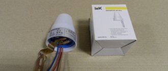
Well, some photos and a wiring diagram for all this. Perhaps it will be useful.
The white wire and the white and black wire go to the indicator light bulb (I connected it like this - white and black - to ground, and the white wire - to the dimensions on the dragonfly. It turns out that the light is turned on - the indicator lights up)
Green - to the temperature sensor, which is located on the engine (located on the left side behind the pump closer to the cabin)
Orange to any positive from the ignition switch (do not throw directly on the battery, otherwise it will work constantly, regardless of whether the ignition is on). You shouldn’t connect it to the white wire either - as soon as you turn on the dimensions, it will lie (mine constantly showed a temperature of 120 degrees)
I also installed the original expansion tank, instead of the VAZ garbage.
The coolant temperature sensor (CTS) is an important element of the engine management system that monitors the coolant temperature in the cooling system. The engine control unit receives information from the DTOZH and, in accordance with it, adjusts the composition of the fuel-air mixture, crankshaft speed, and ignition timing.
Design and principle of operation of the coolant temperature sensor
The “progenitor” of the modern coolant temperature sensor was a thermal relay
, which was installed on some engines (for example, in the K-Jetronic distributed injection system). The thermal relay contact is open - the engine is warming up, the contact is closed - the engine is operating at its normal temperature.
Currently, the basis of the coolant temperature sensor is a thermistor
(a resistor that measures resistance depending on temperature). The coolant temperature is monitored continuously. The material used to make a thermistor is usually nickel or cobalt oxide. The peculiarity of these compounds is that as the temperature increases, the number of free electrons increases and, accordingly, the resistance decreases.
Most often, the thermistor, which is located inside the DTOZH, has a negative temperature coefficient
. The sensor has maximum resistance when the engine is cold. A voltage (5V) is applied to the coolant temperature sensor, and as the resistance changes, it decreases. The engine control unit records voltage changes and, in accordance with it, determines the coolant temperature.
Types of smoke detectors
The detector sensor detects even small smoke
Room analysis smoke detectors are the most popular means of detecting fire signs known. Every combustion process (paper, textiles, electrical equipment, etc.) is accompanied by the formation of smoke. Such devices are capable of notifying people about a fire in the early stages of its development, when their life and health, as well as property, are not in danger. For this reason, this type of sensors can be found in apartments, public buildings, and warehouses.
Operating principle: The functioning of the smoke analyzer is based on the dispersion of the light flux through smoke microparticles. The luminous flux is created using an LED that operates in the infrared range. If there is smoke in the protected area, some part of the photon flux is reflected from smoke particles, about which information is sent to the receiver. The built-in microprocessor analyzes the received data, after which it switches the detector to the “Alarm” position.
For different positions of emitters and receivers, smoke sensors can be linear or point. The name of devices of this type begins with “IP 212”, which stands for “fire detector”, by the number 2 (two) we mean the “smoke sensor” model, and “12” means the principle of operation, i.e. "optics".
Point detectors
In such a device of this type, the photodetector and the light flux generator are placed on both sides of the smoke reception chamber and are enclosed in one housing. The sensor has perforations on the lid, allowing smoke particles to easily penetrate inside. Based on this, we can conclude that the optical-electronic fire smoke detector analyzes the level of smoke in the protected area of the building at a specific point. The advantage of smoke analyzers is their compact housing, ease of installation and cleaning, and effective smoke detection. Point detectors are mounted on the ceiling at a certain distance, which is calculated according to the height of the ceilings in the room. In some cases, placement on walls and other structural elements of buildings and structures is allowed.
The simplified diagram shows that when smoke appears, part of the radiation is reflected from it and hits the photocell
Where is the coolant temperature sensor located?
The thermistor is located inside a protective heat-conducting housing, and on the housing itself there is a thread for attaching the sensor, as well as an electrical connector. Typically, the DTOZH is screwed into the exhaust pipe of the cylinder head. Some engines have two sensors at once: one records the temperature at the engine outlet, the second - from the radiator.
The coolant temperature sensor is positioned so that its tip has direct contact with the coolant. Accordingly, if there is little antifreeze in the system, then the DTO indicators may be inaccurate.
Signs of DTOZH malfunction
Like any other sensor, the DTOZH can fail, causing engine malfunctions. The first signs by which you can recognize a breakdown of the coolant temperature sensor:
- problems starting the engine in cold weather,
- bad exhaust on a cold engine,
- increased fuel consumption, etc.
Most often, if such symptoms occur, replacing the coolant temperature sensor is not necessary.
. Most likely, the problem is a loose or damaged contact, damaged wiring, or a coolant leak. Therefore, first you should conduct a visual inspection of the sensor for damage or corrosion.
Why do you need a stabilizer for an electric boiler?
A voltage stabilizer is an automatic device for electric heating boilers, which, like a thermostat, allows you to save money. But in this case, we are not talking about efficient energy consumption, but about the integrity and performance of the heating element as a whole.
A stabilizer for an electric heating boiler allows you to smooth out all differences in the operating characteristics of the electrical network during the day and obtain the correct sinusoidal voltage at the output, which will have a beneficial effect on the durability of the boiler. Stabilizers provide a high degree of protection of electrical appliances from ripple and voltage surges. High-quality equipment is highly sensitive, which is important for the electronic part of the boiler and thermostat. Stabilizers are characterized by an increased margin of network output power. This allows you to maintain the operating characteristics of the electrical network at the proper level even when the boiler is turned on.
Before purchasing a stabilizer, you must consult a specialist and clearly determine the type of equipment needed and its power.
Checking the coolant temperature sensor
If the inspection does not produce results, it is necessary to measure the resistance and voltage of the sensor at different temperatures
. After starting a cold engine, as it warms up, the resistance should drop (or increase in the case of a positive temperature coefficient of the sensor) in accordance with normal values.
You can check the coolant temperature sensor yourself
Normal resistance and voltage readings for a NTC coolant temperature sensor
| Coolant temperature (°C) | Resistance (Ohm) | Voltage (V) |
| 4800 – 6600 | 4,00 – 4,50 | |
| 10 | 4000 | 3,75-4,00 |
| 20 | 2200 – 2800 | 3,00 – 3,50 |
| 30 | 1300 | 3,25 |
| 40 | 1000-1200 | 2,50 – 3,00 |
| 50 | 1000 | 2,5 |
| 60 | 800 | 2,00-2,50 |
| 80 | 270 – 380 | 1,00-1,30 |
| 110 | 0,5 | |
| open circuit | 5,0 ±0,1 | |
| short circuit to ground |
Normal resistance and voltage indicators for DTOZh with a positive temperature coefficient
AutoOt.ru » Car repair » Where is the coolant temperature sensor located?
Sketch for DS18B20
The algorithm for obtaining temperature information in a sketch consists of the following steps:
- Determining the sensor address, checking its connection.
- A command is sent to the sensor with the requirement to read the temperature and put the measured value into the register. The procedure takes longer than others, requiring approximately 750 ms.
- A command is issued to read information from the register and send the resulting value to the “port monitor”,
- If required, conversion to Celsius/Fahrenheit is performed.
Example of a simple sketch for DS18B20
The simplest sketch for working with a digital sensor looks like this. (in the sketch we use the OneWire library, which we’ll talk about in more detail a little later).
#include /* * Description of interaction with the digital sensor ds18b20 * Connecting the ds18b20 to the Arduino via pin 8 */ OneWire ds(8); // Create a OneWire object for the 1-Wire bus, which will be used to work with the sensor void setup(){ Serial.begin(9600); } void loop(){ // Determine the temperature from the DS18b20 sensor byte data[2]; // Place for temperature value ds.reset(); // We begin interaction by resetting all previous commands and parameters ds.write(0xCC); // We give the DS18b20 sensor a command to skip the search by address. In our case, only one device ds.write(0x44); // We give the DS18b20 sensor a command to measure the temperature. We do not yet receive the temperature value itself - the sensor will put it in the internal memory delay(1000); // The microcircuit measures the temperature, and we wait. ds.reset(); // Now we are preparing to receive the value of the measured temperature ds.write(0xCC); ds.write(0xBE); // Please pass us the value of the registers with the temperature value // Receive and read the response data[0] = ds.read(); // Read the low byte of the temperature value data[1] = ds.read(); // And now the senior // We form the final value: // - first we “glue” the value together, // - then we multiply it by the coefficient corresponding to the resolution (for 12 bits the default is 0.0625) float temperature = ((data [1] << | data[0]) * 0.0625; // Output the resulting temperature value to the port monitor Serial.println(temperature); }
Sketch for working with ds18b20 sensor without delay
You can complicate the program for ds18b20 a little to get rid of the delay() function, which slows down the execution of the sketch.
#include OneWire ds(8); // OneWire object int temperature = 0; // Global variable for storing the temperature value from the DS18B20 sensor long lastUpdateTime = 0; // Variable for storing the time of the last reading from the sensor const int TEMP_UPDATE_TIME = 1000; // Determine the frequency of checks void setup(){ Serial.begin(9600); } void loop(){ detectTemperature(); // Determine the temperature from the DS18b20 sensor Serial.println(temperature); // Output the resulting temperature value // Because the temperature variable is of type int, the fractional part will simply be discarded } int detectTemperature(){ byte data[2]; ds.reset(); ds.write(0xCC); ds.write(0x44); if (millis() - lastUpdateTime > TEMP_UPDATE_TIME) { lastUpdateTime = millis(); ds.reset(); ds.write(0xCC); ds.write(0xBE); data[0] = ds.read(); data[1] = ds.read(); // Form the value temperature = (data[1] << + data[0]; temperature = temperature >> 4; } }
DallasTemperature and DS18b20 library
In our sketches we can use the DallasTemperature library, which simplifies some aspects of working with the ds18b20 sensor over 1-Wire. Sketch example:
#include // Number of the Arduino pin with the connected sensor #define PIN_DS18B20 8 // Create a OneWire object OneWire oneWire(PIN_DS18B20);
// Create a DallasTemperature object for working with sensors, passing it a link to an object for working with 1-Wire. DallasTemperature dallasSensors(&oneWire); // Special object for storing the device address DeviceAddress sensorAddress; void loop(void){ // Request for measurements with a temperature sensor Serial.print("Measuring temperature..."); dallasSensors.requestTemperatures(); // Ask ds18b20 to collect data Serial.println("Done"); // Request to get the stored temperature value printTemperature(sensorAddress); // Delay so that something can be seen on the screen delay(1000); } // Helper function for printing the temperature value for the device void printTemperature(DeviceAddress deviceAddress){ float tempC = dallasSensors.getTempC(deviceAddress); Serial.print("Temp C: "); Serial.println(tempC); } // Helper function to display the address of the ds18b20 sensor void printAddress(DeviceAddress deviceAddress){ for (uint8_t i = 0; i < 8; i++) { if (deviceAddress < 16) Serial.print("0"); Serial.print(deviceAddress , HEX); } }
How to check the coolant temperature sensor?
In order to check the device, it must first be removed.
Dismantling is very simple:
- As a rule, the sensor is located on the cylinder head pipe and in order to remove it, you first need to remove the air filter;
- then the negative cable is removed from the battery;
- coolant is drained from the radiator;
- the wiring is disconnected from the device;
- using a suitable wrench (most often 19–21), the tightening is loosened, after which the sensor can be easily dismantled.
After the sensor has been removed, it is placed in a container with coolant and it is gradually heated. The process is accompanied by constant monitoring of the temperature and the readings of an ohmmeter, which is connected to the sensor.
There is a special table corresponding to the coolant temperature and ohmmeter readings.
| Temperature, °C | Resistance, Ohm | Voltage, V |
| 4800 — 6600 | 4,00 — 4,50 | |
| 10 | 4000 | 3,75-4,00 |
| 20 | 2200 — 2800 | 3,00 — 3,50 |
| 30 | 1300 | 3,25 |
| 40 | 1000-1200 | 2,50 — 3,00 |
| 50 | 1000 | 2,50 |
| 60 | 800 | 2,00-2,50 |
| 80 | 270 — 380 | 1,00-1,30 |
| 110 | 0,50 | |
| open circuit | 5,0 + 0,1 | |
| short circuit to ground |
When the readings from your device do not agree with the data from the table, the sensor must be replaced, since it can no longer be repaired.
If it turns out that the sensor is in working order, the fault needs to be looked for further. There may be some problem with the thermostat.
You can see an example of how to check the coolant temperature sensor by watching this video:
Varieties
Among the popular brands/models of fire and security sensors on the market, the following products should be highlighted (at the time of writing):
- IP 22051TEI-63-IV is a model of an addressable analogue combined (heat/smoke) detector from the Sphere of Security enterprise. Protection area – 176 sq. m. Dimensions – diameter 102 mm, height 61 mm, weight only 88 g.
- IP 212/101-Bark is a combined detector with heat and smoke sensors combined in one housing. Manufacturer: NPO PAS. Power supply via AL 24 V. Protection – IP Operating temperature range – from – 30 to + 55℃. The maximum number of detectors in the AL is 63 pcs. Dimensions – diameter 100 mm, height 78 mm with a weight of 0.2 kg, which does not exceed the dimensions and weight of a traditional optical smoke detector.
- There are also product models under the abbreviation IP 212/101 from other manufacturers - this is ECO1002, also known as IP 212/101-2-A1R from; IP 212/101-11-PR from ; "Aurora-DTR" (IP 21210/10110-1-A1) from the manufacturer "Argus-Spectrum", operating via a radio channel with a control panel at a range of up to 600 m, as well as a number of other enterprises with similar technical characteristics.
- “S2000-IPG” is a combination of a gas sensor, which determines the content of carbon monoxide in the air, and a maximum differential thermal sensor, combined in a compact housing of an addressable analogue fire detector, the dimensions of which are 100 mm in diameter and 47 mm in height. Power supply: 12 V. Installation type: ceiling. In production.
- IPK-3.3/IPK-3.5 – four- and two-wire combined (smoke/heat) detectors from Ukrainian, operating on a 12/24 V alarm loop.
- MSD-300 is a radio channel combined smoke and heat detector, TSD-1 is a similar device, with 12 V power supply via an alarm loop from Satel from Poland.
- Panasonic 4400 is a multi-sensor smoke detector that, thanks to automatic settings, can be installed in clean, smoky, and hot rooms.
- "Sokol-2" is a combined security detector designed to detect illegal access to enclosed spaces. Its official abbreviation is IO 414-1. It implements double control of the volume of protected space according to two parameters - IR/microwave, i.e. registration of changes in IR radiation after a person crosses control zones formed by an optical sensor, as well as changes in the electromagnetic field created by a microwave sensor. When triggered in any sequence, they generate an alarm by opening the output relay contacts. Range – 12 m. Installation method – wall-mounted. Dimensions – 135x70x50. Can be used at temperatures from – 30 to + 50℃.
- “Sokol-3” is a model of a similar IR/microwave volumetric security detector, designed for installation on the ceiling of a protected room. Dimensions – diameter 90 mm, height 35 mm. The detection range of the sensors is 5 m. Both security detectors are produced domestically.
- The family of security and radio-channel fire detectors with the Astra trademark is a Russian product. Among them are combined IS: “Astra-551” – IR/radio wave security detector with a range of 10 m, detection zone angle 90; "Astra-641" - with an IR/ultrasonic sensor.
The choice is quite large, there are no problems choosing a combined fire and security detector, incl. one manufacturer; because Leading companies that manufacture fire alarm systems, as a rule, produce lines of models of both types, which ensures ease of design using ready-made circuits, full compatibility, reliability of equipment operation, reduced energy consumption, and simplified installation work.
Types of combined fire detectors
Signs of DTOZH malfunction
The liquid cooling sensor, like any other sensor, can have malfunctions that will someday lead to engine malfunctions.
The main signs that indicate a device failure:
- increased fuel consumption;
- poor exhaust when the engine is cold;
- Problems starting the engine in cold weather.
As a rule, if such problems occur, replacement of the sensor is not required. The problem may have arisen due to a loose or damaged contact, a wiring problem, or a leak of cooling fluid.
Sometimes a cold engine stalls and stalls, and its idle speed jumps from minimum to maximum values per minute, and after a few minutes or after a restart the situation is corrected.
This problem can occur due to a breakdown of the cooling fluid temperature sensor.
You can check the condition of the device using an ohmmeter. There is no need to unscrew it. It is not its resistance that is checked, but the mass sensor.
When the sensor is in order, the resistance tends to infinity, but if it is broken, then the resistance is 10 kOhm or less.
Calibrations
Fixed point tuning is used to obtain the highest accuracy by national metrology laboratories.
It uses the triple point, the freezing or melting point of pure substances such as water, zinc, tin and argon, to create a known and repeatable temperature. These cells allow the user to reproduce actual conditions on the ITS-90 temperature scale. Fixed point calibration provides extremely precise adjustment (within ±0.001°C). A common fixed-point calibration method for industrial sensors is the ice bath. The equipment is inexpensive, easy to use, and can accommodate multiple sensors simultaneously. The ice point is designated as a secondary standard because its accuracy is ±0.005 °C (±0.009 °F) compared to ±0.001 °C (±0.0018 °F) for the primary fixed points.
Comparative calibrations are commonly used with secondary SPRTs and industrial RTDs. Calibrated thermometers are compared with tuned resistance thermometers using a bath whose temperature is uniformly stable.
Unlike fixed-point calibration, comparison can be made at any temperature from −100 °C to 500 °C (–148 °F to 932 °F). This method can be more cost-effective because multiple sensors can be calibrated simultaneously using automatic equipment. These electrically heated, well-mixed water baths use silicone oils and molten salts as a medium for varying temperature settings.
How to connect the coolant temperature sensor?
The sensor is installed very easily: it is screwed into the mounting socket, after which the thread is tightened and the wiring is connected, the air filter is put in place and the main air flow sensor power supply block is connected.
It is strictly forbidden to use sealant in this case. When the engine is running, the cooling system and metal elements become very hot, and the sealant may melt.
If this happens, the sealant will get into the antifreeze and the cooling system may fail.
Coolant temperature sensor connection diagram:
Replacing DTOZH, video:
Accommodation options
Thermal sensors can be installed in different places; they can also be divided into several groups:
- Overlays are attached tightly to the surface, which is heated;
- Submersible units are installed directly with the coolant;
- Room ones that measure ambient temperature;
- External, used for installation outside the premises.
Checking the coolant level
Many car owners often check the coolant level visually without using special instruments. You just need to look at the expansion tank.
If the engine is cold, the coolant should be between the maximum and minimum marks on the reservoir. When the engine is warm, the level of the substance may increase slightly.
If your car is in full working order, then when the antifreeze level decreases, the sensor immediately lets you know about it. The driver sees a special signal on the dashboard and adds antifreeze or coolant.
It is also contraindicated to add water alone. After all, antifreeze has special properties that protect cylinder heads from corrosion.
If checking the coolant temperature sensor does not show the coolant temperature. In this case, you better contact technical service.
In any car, everything is interconnected. The car system could fail for some related reason. For example, you could remove some part located with the sensor and place it incorrectly.
But it also happens that the problem is related specifically to the temperature sensor. The coolant level may be inconsistent or there may be a problem with the coolant level sensor.
The service can replace the sensor, and they provide a guarantee for its high-quality replacement and the correct assembly of all parts in the right places.
Thus, the coolant temperature sensor is a very important component of your car, which requires constant attention and care.
If repair of this device is necessary, then do it efficiently, without regretting the money spent. After repair, the engine will run smoothly, this will be especially noticeable at low speeds.
>
Connection features
Both in production and in residential buildings, the main purpose of fire detectors is not only to detect potential danger, but also to convey a message about it to firefighters. This allows you to urgently respond to fires and smoke before they become catastrophic, even though there may be no one in the room to raise the alarm. Accordingly, the detector must be connected not only to the power supply, but also to a receiving station located directly at the fire station.
Not all fire alarm systems automatically send a message about the situation - some can only trigger a siren, warning everyone present of the problem. So, in places where there are always people, inexpensive manual call points are more often used - it’s like a fire alarm button, someone has to press it. Automatic detectors respond to sensor readings, so the signal is sent without human intervention. In any case, a communication channel and an end subscriber are needed to transmit the signal, therefore, without the direct participation of the fire service, installing a fire alarm makes no sense. The stations to which the detectors are connected are different - they are designed for different types of sensors themselves and usually have a limit on their maximum quantity. For this reason, even in the process of drawing up a system plan, you need to select a suitable station and agree with firefighters about its installation and maintenance.