Electric motor power is a passport characteristic of a device that converts electrical energy into kinetic energy. This is one of the key parameters when choosing a device to service various equipment. It is always indicated in the accompanying documentation and is additionally “stamped” on the electric motor nameplate attached to its body.
But documents are not always saved, and the inscription on the nameplate may become erased. In such cases, for further operation, testing, and connection, it may be necessary to calculate the power of the electric motor. It is produced in different ways, which we will talk about.
Electric motor power concept
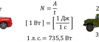
Power is perhaps the most important parameter when choosing an electric motor. Traditionally, it is indicated in kilowatts (kW), for imported models - in kilowatts and horsepower (hp, HP, Horse Power). For reference: 1 hp. approximately equal to 0.75 kW.
The engine nameplate indicates the rated net (output mechanical) power
. This is the power that the engine can deliver to a mechanical load with the stated parameters without overheating. In the formulas, the rated mechanical power is denoted by P2.
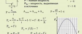
Electrical (consumption) power
motor P1 is always greater than the output P2, since there are losses in any energy conversion device. The main losses in an electric motor are mechanical, caused by friction. As you know from a physics course, losses in any device are determined through efficiency (ƞ), which is always less than 100%. In this case, the formula is valid:
Р2 = Р1 · ƞ
The efficiency in engines depends on the rated power - for low-power models it can be less than 0.75, for powerful ones it exceeds 0.95. The above formula is valid for active power consumption. But, since the electric motor is an active-reactive load, to calculate the total power consumption S
(taking into account the reactive component) it is necessary to take into account reactive losses. The reactive component is expressed in terms of power factor (cosϕ). Taking this into account, the formula for the rated engine power looks like this:
Р2 = Р1 · ƞ = S · ƞ · cosϕ
Calculation of electric motor efficiency
Online calculation of efficiency (efficiency) of an electric motor
Calculation of the efficiency of a three-phase electric motor
The efficiency of the electric motor is calculated using the following formula:
η=P/√3UIcosφ
Where:
- P - Rated power of the electric motor (taken from the motor’s passport data or determined by calculation);
- U - Rated voltage (voltage to which the electric motor is connected);
- I - Rated current of the electric motor (taken from the passport data of the electric motor , and in their absence, determined by calculation);
- cosφ - Power factor - the ratio of active power to total power (taken from 0.75 to 0.9 depending on the power of the electric motor);
Did you find these online calculators useful? Or maybe you still have questions ? Write to us in the comments!
Didn’t find an article on the website on a topic that interests you regarding electrical engineering? Write to us here. We will definitely answer you.
↑ Up
7,5
https://elektroshkola.ru/kalkulyatory/onlajn-raschet-xarakteristik-trexfaznyx-elektrodvigatelej/
Engine power and heating
The rated power is usually specified for an ambient temperature of 40°C and is limited by the maximum heating temperature. Since the weakest point in a motor in terms of overheating is insulation, power is limited by the insulation class of the stator winding. For example, for the most common insulation class F, the permissible heating is 155°C at an ambient temperature of 40°C.
The documentation for electric motors provides data that shows that the rated power of the motor drops as the ambient temperature rises. On the other hand, with proper cooling, engines can operate at higher than rated power for a long time.
We have looked at the power consumption and output, but it should be said that the actual operating power consumption P
(motor shaft power at a given moment) should always be less than rated:
R 2 1
This is necessary to prevent engine overheating and to have an overload reserve. Short-term overloads are permissible, but they are limited primarily by engine heating. It is also advisable to install motor overload protection not based on the rated current (which is directly proportional to power), but based on the actual operating current.
Modern manufacturers mainly produce engines from a number of ratings: 1.5, 2.2, 5.5, 7.5, 11, 15, 18.5, 22 kW, etc.
Standardized requirements for indicators
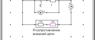
In the Russian Federation, requirements for the quality of power system operation are standardized.
In accordance with GOST 13109-97, the frequency in the power system must be continuously maintained at the level f = 50 ± 0.2 Hz, while a short-term frequency deviation up to ∆f = 0.4 Hz is allowed.
Analyzing the dependence of current on frequency, we can conclude that if the connected load is purely active in nature (for example, a resistor), then over a wide range the current will not have a dependence on frequency. In the case of sufficiently high frequencies, when the inductance and capacitance of the connected load are characterized by a resistance comparable to the active one, the current strength will have a certain dependence on frequency.
In other words, when the frequency of the current varies, a change in capacitance occurs, a change in which, in turn, leads to a change in the current flowing through the circuit.
That is, as the frequency increases, the capacitance decreases and the current flowing through the circuit increases.
The mathematical expression of the dependence will have the following form: I = UCω;
The dependence, taking into account active resistance, will be determined by the following expression: I (ω) = UCω √(R2 • C2 • ω2 + 1).
Engine power calculation based on measurements
In practice, the motor power can be calculated primarily from the operating current. The current is measured by current clamps in the maximum operating mode, when the operating power approaches the rated power. In this case, the temperature of the motor housing can exceed 100 °C, depending on the heat resistance class of the insulation.
We substitute the measured current into the formula to calculate the real mechanical power
on the shaft:
P = 1.73 U I cosϕ ƞ
, Where
- U – supply voltage (380 or 220 V, depending on the connection diagram - “star” or “delta”),
- I – measured current,
- cosϕ and ƞ – power factor and efficiency, the values of which can be taken equal to 0.8 for low-power motors (less than 5.5 kW) or 0.9 for motors with a power of more than 15 kW.
If you need to find the rated power
engine, then the resulting result is rounded up to the nearest value from the range of denominations.
P2 > P
If you need to calculate the active power consumption
, we use the following formula:
P1 = 1.73 U I ƞ
It is the active power that electricity meters measure. In industry, additional equipment is used to measure reactive (and apparent power S). With this method, you can not use the above formula, but do it in a simpler way - if the motor is connected to a “star”, we multiply the measured current value by 2 and get the approximate power in kW.
What's more important: power or torque?
Want to create a site? Find Free WordPress Themes and plugins.
Many people believe that the most important characteristic of any electric motor is power . about such an important parameter as “ torque ” and not everyone understands its importance for traction electric drives.
Graph of power (P) and torque (M) versus speed (n), where: Mnom - rated torque (in S1 mode), N*m; Mmax — maximum torque (in S2 mode), N*m; Pnom – rated power (in S1 mode), kW; Pmax – maximum power (in S2 mode), kW; N – nominal speed, rpm
From the graph of the dependence of the power of a synchronous electric motor on the revolutions, it can be seen that its power is not a constant value, but in the operating speed range it increases linearly as the speed increases. To accurately determine the power (P) of an electric motor, the optimal point on the graph is selected as its technical characteristic, which determines the rated power (Pnom) at rated speed (N) .
By increasing the rated speed of a synchronous electric motor, it is possible to proportionally increase its rated power, which, in turn, leads to an increase in power density .
In pursuit of power
Most designers and manufacturers of electrical machines try to achieve high power by increasing the rated speed to several thousand or even tens of thousands of revolutions per minute. However, as the speed of an electric machine increases, several unpleasant problems avalanche-like increase at once: starting with mechanical balancing of the rotor and ending with high-frequency losses in the stator. The main high-frequency problems are the so-called “skin effect” in windings, Foucault eddy currents in the core and the speed of power switches of frequency converters. Overcoming these problems leads to a significant increase in the cost of the electric motor.
Rotating force
For traction electric drives, it is necessary, first of all, to provide the required rotational force, which is also called “moment of force” or “ torque ” (M) . In such systems, the rotating force must reach maximum values starting from the start.
Unlike asynchronous electric motors, it is with synchronous electric motors that the nominal and maximum torques remain constant throughout the entire operating speed range. Constant rated torque is one of the most important advantages of synchronous electric motors and is ensured even at minimum power. , the corresponding torques are designated “ Mnom ” and “Mmax” .
Unfortunately, in real conditions, an increase in the rated speed of the electric motor leads to a decrease in the specific torque (M) . If you want to achieve minimal weight-dimensions of an electric motor, then you will have to choose between the concepts of high specific power due to high speeds and high specific torque at low or ultra-low speeds.
Converting Power to Torque
The creator of any traction electric drive using a high-speed electric motor faces the need to convert power into torque, accompanied by a transition from high to low speeds. This transformation is carried out using a mechanical gearbox .
However, the use of a gearbox leads to an inevitable increase in the complexity, weight, dimensions and cost of the electric drive against the background of a decrease in efficiency, reliability and working life. If we are talking about a servo drive, then any mechanical gearbox, among other things, reduces the positioning accuracy.
Getting rid of the gearbox!
The use of traction synchronous electric motors with high specific torque makes it possible to significantly reduce the reduction coefficient or completely abandon the mechanical gearbox, ensuring the transition to direct drive with all the ensuing advantages.
The specific torque of synchronous electric motors of the iEM series is 5-10 times asynchronous and commutator of similar power ! Such a high torque of electric motors / iEM allows you to either significantly reduce the reduction ratio or completely abandon the mechanical gearbox!
Thanks to patented technologies, synchronous electric motors of the / iEM series are 2-5 times more compact and lighter than other synchronous (including “valve”) and commutator electric motors with the same torque!
Constant power mode
The graph of the dependence of power and torque on revolutions shows that when the rated speed ( N ) of a synchronous electric motor is exceeded, its torque ( M ) begins to decrease. Efficiency also drops. This happens because almost any electric machine is reversible, and can simultaneously work as an electric motor and as an electric generator. When the rated speed is exceeded, the voltage generated by the electric motor begins to “fight” with the supply voltage from the frequency converter. The more the speed increases relative to the nominal speed, the more the electric motor affects the power source, reducing the efficiency and torque of the electric drive.
In practice, exceeding the speed by 20-30% relative to the nominal speed is not always considered as an undesirable or prohibited range for a synchronous electric drive. For example, in electric vehicles, the rev range exceeding the nominal speed is often used to briefly achieve maximum speed, when the efficiency factor temporarily fades into the background. At the same time, modern frequency converters are well able to cope with this situation, and automatically switch to the “ constant power ” mode.
Thus, the optimal choice of rated speed ( N ), as well as the admissibility and extent of their excess for a particular synchronous electric drive, is a thoughtful decision by the electric drive designer, based on specific priorities.
Did you find apk for android? You can find new Free Android Games and apps.
Previous
|
Next
Power calculation using an electricity meter
This method is simple and does not require additional tools or knowledge. It is enough to connect the motor through a meter (three-phase metering unit) and find out the difference in readings over a strictly defined time. For example, when the engine is running for an hour, the difference in the meter readings will be numerically equal to the active power of the engine (P1). But to get the rated power P2, you need to use the above formula.
Other useful materials:
Degrees of protection IP Three-phase motor in a single-phase network Typical faults of electric motors
Calculate engine power consumption
We suggest determining the engine type. Helps to make a nameplate. The apparent power is indicated (reactive plus active, connected through the cosine of the phase angle, called the power factor). If the type of engine is known (found out based on images and appearance), reference books will allow you to find the power. It is not surprising: dimensions are closely related to the parameter; each manufacturer wants to save as much as possible with product output. The dimensions are optimized, the typical set of parameters is as follows:
- Shaft diameter.
- The height of the axle from the base (bed).
AIR engines are described, dimensions, power are indicated here: https://wp.electrostal.com.ua/kakoy-diametr-vala-u-elektrodvigatelya/. Accordingly, you can understand the details without tools. You will see that similar information can be found for almost any type of motor. The nameplate has been torn off, you can spend some time looking for similar models on the Internet. Russia is inferior to China in the variety of electric engines. The chance of success is high.
We believe that we have listed the available methods for determining power and current; it is not a big problem to spend 1000 rubles to get the necessary funds. Considering that the ruble is burning, the move will seem reasonable. It is easier to determine the power of an electric motor using a reference book. You need to know the model, measure the shaft with a caliper.
We finish the review, we hope regular readers know the differences between an asynchronous motor and a commutator motor. We omit the differences
Please also note: asynchronous motors suffer from high starting current. For collectors, the spread is low
When replacing a broken Soviet electric motor with a new one, it often turns out that there is no nameplate on it. We are often asked questions: how to find out the power of an electric motor? How to determine engine speed? In this article we will look at how to determine the parameters of an electric motor without a tag - by shaft diameter, dimensions, current. Order a new electric motor by phone
Common regulator circuits
There are many frequency converters for asynchronous motors, as well as various regulators for them. It is possible to independently make a device for adjusting the frequency using transistors or thyristors. The device works both in everyday life and for machine tools, crane mechanisms, and various adjustable drive units.
A powerful frequency and voltage regulator is shown in the diagram. The device smoothly changes drive parameters, saves energy, and reduces maintenance costs.
To apply this scheme in everyday life, it is difficult. If you use a triac as a working element, the circuit is simplified and looks different.
The adjustment will take place by operating a potentiometer, which determines the phase of the input pulse and opens the triac.
The effect of operating machines that process metal and lifting devices also follows from the rotation of the engine, as do its operational parameters themselves. There are many devices on sale for adjusting frequency, but it is quite possible to assemble such a device on your own.
Early developments
In 1821, after the discovery of the phenomenon of the connection between electricity and magnetism by the Danish chemist Oersted, Ampere’s theorem and Biot-Savart’s law, the English physicist Michael Faraday built two devices, which he called “electromagnetic rotation”: the continuous circular movement of the magnetic force around the wire is the actual demonstration of the first electric motor.
In 1822, Peter Barlow built what can be considered the first electric motor in history: the Barlow wheel. This device consists of a simple metal disk cut into a star, the ends of which are immersed in a cup containing mercury, providing a flowing stream. However, it only creates a force capable of turning it, preventing its practical use.
The first experimentally used commutator was invented in 1832 by William Sturgeon. The first commercially manufactured DC motor was invented by Thomas Davenport in 1834 and patented in 1837. These engines did not experience any industrial development due to the high cost of batteries at the time.
Electric motor with DC
A DC switched apparatus has a set of rotating windings wound around an armature mounted on a rotating shaft. The shaft also contains a commutator, a long-lasting rotary electrical switch that periodically changes the flow of current in the rotor windings as the shaft rotates. Thus, each DC bridge motor has alternating current passing through the rotating windings. Current flows through one or more pairs of brushes that are carried on the commutator; brushes connect an external power source to the rotating armature.
A rotating armature consists of one or more spools of wire wound around a laminated ferromagnetic core. The current from the brush flows through the commutator and one armature winding, making it a temporary magnet (electromagnet). The magnetic field produced by the armature interacts with the stationary magnetic field produced by either the PM or another winding (field coil) as part of the motor frame.
The force between the two magnetic fields tends to rotate the motor shaft. The commutator switches power to the coils as the rotor turns, keeping the magnetic poles from ever completely matching the stator's magnetic poles so that the rotor never stops (like a compass needle), but rather rotates as long as there is power.
Although most switches are cylindrical, some are flat disks consisting of several segments (usually at least three) mounted on an insulator.
Large brushes are desirable for a larger brush contact area, to maximize motor power, but small brushes are desirable for low mass, to maximize the speed at which the motor can operate without excessive kickback and brush sparking. Stiffer brush springs can also be used to produce brushes of a given mass at higher speeds, but at the expense of greater friction and wear on the accelerated brush and commutator. Therefore, DC motor design entails a trade-off between power output, speed, and efficiency/wear.
Design of DC motors:
- The valve circuit is a winding; it carries the load current, which can be a stationary or rotating part of an engine or generator.
- Field circuit - a set of windings that create a magnetic field so that electromagnetic induction can exist in electrical machines.
- Switching. A mechanical technique in which rectification can be achieved, or whereby direct current can be obtained.
There are four main types of DC motors:
- Electric motor with shunt winding.
- DC motor.
- Combined engine.
- Engine PM.
https://youtube.com/watch?v=sCVZ7tsluC8
Engine types
DC and AC motors
Depending on the electric current used, motors are divided into two groups:
- DC drives;
- AC drives.
DC motors are not used as often today as they used to be. They have practically been replaced by asynchronous motors with squirrel-cage rotors.
The main disadvantage of DC electric motors is that they can only be operated with a DC source or an AC-to-DC converter. In modern industrial production, ensuring this condition requires additional financial costs.
However, with significant disadvantages, this type of motor is characterized by a high starting torque and stable operation under conditions of high overloads. Drives of this type are most often used in metallurgy and machine tool construction and are installed on electric vehicles.
The operating principle of AC electric motors is based on electromagnetic induction that occurs during the movement of a conducting medium in a magnetic field. To create a magnetic field, windings flowing around currents or permanent magnets are used.
AC electric motors are divided into synchronous and asynchronous. Each subgroup has its own design and operational features.
Synchronous electric motors
Synchronous motors are the optimal solution for equipment with constant operating speed: DC generators, compressors, pumps, etc.
The technical characteristics of synchronous electric motors of different models differ. The rotation speed ranges from 125 to 1000 rpm, the power can reach 10 thousand kW.
The design of the drives includes a short-circuited winding on the rotor. Its presence allows for asynchronous engine starting. The advantages of equipment of this type include high efficiency and small dimensions. The operation of synchronous electric motors allows you to reduce electricity losses in the network to a minimum.
Asynchronous electric motors
Asynchronous AC motors are most widely used in industrial production. A feature of these drives is a higher frequency of rotation of the magnetic field compared to the speed of rotation of the rotor.
Modern engines use aluminum to make the rotor. The light weight of this material makes it possible to reduce the weight of the electric motor and reduce the cost of its production.
The efficiency of an asynchronous motor drops almost by half when operating at low loads - up to 30-50 percent of the nominal value. Another disadvantage of such electric drives is that the starting current parameters are almost three times higher than the operating parameters. To reduce the starting current of an asynchronous motor, frequency converters or soft starters are used.
Asynchronous motors meet the requirements of various industrial applications:
- For elevators and other equipment requiring stepwise speed changes, multi-speed asynchronous drives are produced.
- When operating winches and metalworking machines, electric motors with an electromagnetic braking system are used. This is due to the need to stop the drive and fix the shaft in case of power outages or disappearance.
- In processes with a pulsating load or in intermittent modes, asynchronous electric motors with increased sliding parameters can be used.
Valve motors
The group of valve electric motors includes drives in which the operating mode is controlled by means of valve converters.
The advantages of this equipment include:
- High service life.
- Easy maintenance due to contactless control.
- High overload capacity, which is five times the starting torque.
- Wide speed control range, which is almost twice the range of asynchronous electric motors.
- High efficiency at any load - more than 90 percent.
- Small dimensions.
- Fast payback.
Designations of the main mounting and connecting dimensions of motors
Legend for overall dimensions:
- h is the height of rotation of the shaft or the size of the electric motor. Height from the center of the shaft axis to the ground. Important connection size when assembling the unit and aligning it
- l30*h31*d24 - length, height, width of the AIR electric motor, dimensions. Necessary for calculating the cost of delivery and the required space during transportation
- m is the weight of the electric motor, mass. Needed to calculate transport costs and strength of materials
- d1 - shaft diameter. Overall connection size of the AIR required when aggregating with other equipment or selecting a coupling half
- d20 - width, mounting diameter of the flange. d22 is the diameter of the flange holes. Overall dimensions for manufacturing or selecting a counter flange
- l10 and b10 – the distance between the mounting holes on the motor feet. Important overall and installation dimensions required when mounting the electric motor to a frame or platform
- L1 – shaft length
- b1 – key width. The size required for the manufacture of the coupling half
Mounting design – flange, feet, combined
Connection and dimensional drawing of the installation design of the AIR electric motor on feet (IM 1081), feet-flange (IM 2081), clean flange (IM 3081).