In each electrical circuit there are so-called P - edges (they are also branches, links, sections) and U - nodes. To describe it, there is a system of equations that use two Kirchhoff rules. In them, the edge currents act as independent variables. Therefore, the number of independent variables will be equal to the number of equations, which makes it possible to resolve the given system normally. In practice, methods are used aimed at reducing the number of equations. Among them, the loop current method is very often used, which allows you to perform calculations and obtain accurate results.
Basic principles
Any electrical circuit consists of sections (branches) that form nodes and circuits. To determine the current values through any element, two Kirchhoff laws are used. Direct composition of equations gives a system with their maximum number equal to the number of branches. As a result, if the set of nodes in the chain is Y, and the number of branches is P, then the equations are distributed as follows:
- For U-1 nodes, according to Kirchhoff’s law for currents;
- For branches R-U+1 according to Kirchhoff’s law for stresses.
This quantity is excessive and leads to the formation of a cumbersome system of high-dimensional equations.
To simplify calculations, techniques have been developed that allow reducing the number of equations to acceptable values without reducing the accuracy of the results. The simplest is the loop current method.
Additional circuit calculation methods
Connecting an LED through a resistor and calculating it
Depending on the complexity of the device (electrical circuit), the optimal computing technology is selected.
Nodal voltage method
The basic principles of this method are based on Ohm's law and Kirchhoff's postulates. At the first stage, the potentials at each node are determined. Next, the currents in the individual branches are calculated taking into account the corresponding electrical resistances (individual components or equivalent values). The check is done according to the rules discussed.
Equivalent generator method
This technology is suitable for quickly calculating the current in one or more control branches.
Graphic explanation
In this technique, the general circuit is represented as a current source with a certain voltage and internal resistance. Next, calculations are performed along the control branch using a standard algorithm.
Optimized system composition procedure
According to a simplified method, proceed as follows:
- In the equations on the left side we write the product of the sum of all resistances included in the circuit and the circuit current;
- From the resulting expression, the adjacent loop currents multiplied by the sum of the resistances of the common branch are subtracted;
- On the right is written the sum of the circuit's EMF sources.
Formal approach
The system of equations for MCT, written in a matrix representation, is called a formal approach. The following matrices are required for calculations:
- C - consists of i rows and j columns, where i is the number of rows, j is the number of columns;
- Z is a diagonal resistance matrix, the number of rows and columns is equal to the number of branches;
- Сt is the transposed C-matrix. In a transposed matrix, the rows and columns are swapped;
- I—CT matrix (consists of one column);
- J—matrix-column—current sources;
- E is a column matrix containing EMF sources with one or another sign.
The final equation for calculations in matrix representation is as follows:
C * Z * St * I = C * (E + Z * J)
Example of a system of equations
Below is an example of calculating a specific circuit without taking into account the nominal values of the elements.
Example solution
In a given circuit there are three circuits. How to express currents in branches through contour ones:
- i1=I1;
- i2=I2;
- i3=I3;
- i4=I2+I3;
- i5=I1+I2;
- i6=I1-I3.
How to create a system of equations:
- i1R1+i5R5+i6R6=E1;
- i2R2+i4R4+i5R5=E2;
- i3R3+i4R4-i6R6=0
How to substitute contour values:
- I1R1+( I1+I2)R5+( I1-I3)R6=E1;
- I2R2+( I2+I3)R4+( I1+I2)R5=E2;
- I3R3+( I2+I3)R4-( I1-I3)R6=0
After the transformation, the necessary system of equations is obtained:
- (R1+R5+R6)I1+R5I2+R6I3=E1;
- R5I1+(R2+R4+R5)I2+R4I3=E2;
- -R6I1+R4I2+(R3+R4+R6)I3=0.
A system of three equations can be easily solved after substituting known parameters. From the obtained values of the loop currents, the required values can then be found.
This example of solving problems using the loop current method shows that any sufficiently complex circuit can be significantly simplified for solution, guided by the instructions.
Important! The method is not applicable if it is not possible to transform the chain without mutual intersection of branches.
In some cases, the circuit can be simplified by converting the star-connected branches into a triangle.
Exactly the same results are obtained when using the nodal potential method. The calculations are based on searching for the potential of each node (the so-called nodal potential). There are programs that allow online calculation of parameters using the methods discussed.
Calculation of electrical circuits using Kirchhoff's laws
There are several methods for calculating electrical circuits, which differ in the parameters that need to be found, as well as the number of calculations required.
First, I will tell you how to calculate a circuit in a general form, but as a result, the size of the calculations will be unreasonably large. This calculation method is based on Ohm's and Kirchhoff's laws and is used when calculating small circuits with a small number of circuits. To do this, a system of equations is composed of (q - 1) equations for the nodes of the chain and n equations for independent circuits. Independent contours are characterized by the fact that when constructing equations for each new contour, at least one new branch is included that was not included in the previous contour. Thus, the number of equations in the system of equations for this method of circuit calculation will be determined by the following expression
As an example, let's calculate the electrical circuit shown in the figure below.
An example of an electrical circuit for calculation using Ohm's and Kirchhoff's laws.
As an example, let's take the following circuit parameters: E1 = 50 V, E2 = 30 V, R1 = R3 = 10 Ohm, R2 = R5 = 20 Ohm, R4 = 25 Ohm.
- Let's create an equation using Kirchhoff's first law. Since we have two nodes, we will select node A and create an equation for it. I chose conditionally that currents I1 and I2 flow into the node, and I3 flows out, then the equation will look like
- Let's compose the missing equations using Kirchhoff's second law. In the diagram we have two independent circuits: E1R1R2R4E2R3 and E2R4R5, therefore, choosing an arbitrary direction of the circuits, we will compose the missing two equations. I chose to go clockwise, so the equations look like
Thus, the resulting system of equations will have the following form
Having solved this system, we obtain the following results: I1 ≈ 0.564 A, I2 ≈ 0.103 A, I2 ≈ 0.667 A.
As a result of solving a system of equations using this method, it may turn out that the currents turn out to be negative. This means that the actual direction of the currents is opposite in direction to the selected one.
Calculation method according to Ohm's and Kirchhoff's laws
Before studying computing technologies, it is necessary to clarify the features of typical elements when connected to different power sources. At constant current, the inductive resistance can be neglected. A capacitor is equivalent to an open circuit. You should also take into account the following differences between different types of resistor connections:
- sequential - increases the total resistance;
- parallel - distributes currents over several branches, which improves conductivity.
Ohm's law for a circuit section
Differential automatic machine reliable protection of electrical circuits and people
A typical car battery produces a voltage of U = 12 V. An on-board or external ammeter will show the corresponding value when measured. Connecting the terminals with a wire is unacceptable, as this causes a short circuit. If the conductor is thin (< 1 mm), the high current density in the corresponding cross-section will quickly increase the temperature until thermal destruction of the material and breaking the circuit. This example demonstrates the functionality of a conventional fuse.
After connecting the load, you can check the voltage with a multimeter. The value of this parameter remains unchanged. If the resistance is known (example - R = 50 Ohms), applying Ohm's law ( I = U / R ) will help calculate the current:
I = 12/50 = 0.24 A.
Based on the calculated value, the power is quickly determined using the formula:
P = I2 *R = U2/ R = 0.0576 * 50 = 2.88 W.
For your information. The result of the calculation shown will be useful for finding a suitable resistor. You should make a reserve in the direction of increase. According to the standard of serial products, an element with a nameplate rated power of 5 W is suitable.
In practice, more complex problems have to be solved. So, with a significant line length, it is necessary to take into account the influence of the connecting branches of the circuit. Current will flow worse through a steel conductor compared to a copper analogue. Therefore, it is necessary to take into account the resistivity of the material in the calculation. A short wire can be excluded from the calculation. However, the load can have two elements. In any case, the overall figure is equivalent to a certain circuit resistance. With a series connection, Req = R1 + R2 +…+ Rn. This method is suitable if direct current is used.
Ohm's law for a complete circuit
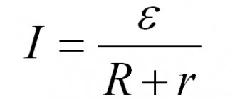
To calculate such a circuit, you should add the internal resistance (Rin) of the source. How to find the current is shown by the following formula:
I = U/ (Req + Rin).
Instead of voltage (U), the standard designation for electromotive force (EMF) - E is often used in calculations.
Kirchhoff's first law
According to the classical formulation of this postulate, the algebraic sum of the currents that enter and exit one node is equal to zero:
I1 + I2 + … + In = 0.
This rule is valid for any connection point of the branches of an electrical circuit. It should be emphasized that in this case the characteristics of individual elements (passive, reactive) are not taken into account. You can ignore the polarity of power supplies connected to individual circuits.
To avoid confusion when working with large circuits, the following use of symbols for individual currents is assumed:
- incoming – positive (+I);
- outgoing ones are negative (-I).
Kirchhoff's second law
This rule establishes the total equality of current sources (EMF) that are included in the circuit under consideration. For clarity, you can see how the distribution of control parameters occurs when two resistors (R1 = 50 Ohm, R2 = 10 Ohm) are connected in series to a battery (Ub = 12 V). To check, measure the potential difference at the terminals of passive elements:
- UR1 = 10 V;
- UR1 = 2 V;
- Uaccb = 12 V = UR1 + UR2 = 10 + 2;
- the current in the circuit is determined according to Ohm's law: I = 12/(50+10) = 0.2 A;
- if necessary, calculate the power: P = I2 * R = 0.04 * (50+10) = 2.4 W.
Kirchhoff's second rule is valid for any combination of passive components in individual branches. It is often used for final verification. To clarify the correctness of the actions performed, add up the voltage drops on individual elements. We should not forget that additional sources of EMF make the result different from zero.
Construction of a system of equations
Resonance in an electrical circuit
The construction of a system of equations using the method under consideration is carried out according to the following rules:
- For each selected contour, the traversal direction is specified;
- On the left side of the equalities, the sum of all products of the desired currents in the branches and the resistance of the branches is written. The right side records the sum of the voltage sources present in the circuit;
- If the direction of the desired quantity or voltage source is the same as that of the given bypass direction, then the terms are written with a plus sign, otherwise they have a negative value;
- The value of the currents in the branches is replaced by their expression through the circuit currents.
After performing arithmetic operations (opening parentheses, bringing similar terms), a system of equations is obtained in which the unknown quantities are virtual loop currents.
By solving a system of equations, the values of the contour and then the required quantities are obtained.
Categories of elements and devices of the electrical circuit
For a conventional representation of a certain circuit, a special diagram is used. In addition to individual physical components, it contains information about the direction (strength) of currents, voltage levels and other information. A high-quality model shows real processes with high accuracy.
Electrical circuit components:
- source of direct or alternating current (E) – battery or generator, respectively;
- passive elements (R) – resistors;
- components with inductive (L) and capacitive (C) characteristics;
- connecting wires.
Typical names
The figure shows:
- branches - sections of a circuit with one current;
- nodes – connection points of several branches;
- circuit - a closed path for current flow.
When solving practical problems, they figure out how to find out the current strength in individual branches. The obtained values are used to analyze electrical parameters. In particular, you can determine the voltage drop across the resistor and the power consumption of the connected load. When calculating AC circuits, it is necessary to take into account transient energy processes and the influence of frequency.
Methods for constructing contours
Careful designation of contours allows you to specify a minimum set of CT scans. Any element of the circuit must be represented in at least one circuit. When constructing, two main methods are used:
- planar graphs;
- selecting a maximum tree.
Using planar graphs
The planar graph method is used for manual calculations, since it is the simplest and most visual. To construct a flat graph, the diagram is drawn in such a way that there is no mutual intersection of branches. It turns out that the diagram can be divided into several limited sections that form contours.
The considered technique is not applicable without additional transformations if it is impossible to express the scheme in the form of a planar graph.
Maximum Tree Allocation
This mathematical method was developed for computer calculations using appropriate software. The main idea of the method is to remove individual branches in accordance with a strict algorithm:
- At each stage, no more than one branch can be removed.
- The removal should not break the graph into separate pieces or lead to "frozen nodes".
- The number of excluded links must be equivalent to the number of independent circuits.
- Connecting the previously removed branch forms the corresponding circuit.
