December 23, 2013
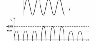
Switching power supplies, thyristor regulators, switches, powerful radio transmitters, electric motors, substations, any electrical discharges near power lines (lightning, welding machines, etc.) generate narrowband and broadband interference of various natures and spectral composition. This complicates the functioning of low-current sensitive equipment, introduces distortions into measurement results, causes failures and even failure of both instrument components and entire equipment complexes.
Based on the nature of their occurrence, interference is divided into antiphase and inphase. The first are formed as parasitic voltage between the forward and return wires of the network. They arise, for example, when there is a large parasitic capacitance between the semiconductor element and the ground and when the signal changes rapidly with a large voltage amplitude. The antiphase interference current in the signal wires coincides in direction with the useful signal current. Common mode voltage occurs as a potential difference between the phase wire, the return wire (the so-called ground or neutral wire) and the ground (device housing, radiator, etc.). The common-mode interference current has the same direction in the forward and return wires of the network.
In symmetrical electrical circuits (ungrounded circuits and circuits with a grounded midpoint), antiphase interference manifests itself in the form of symmetrical voltages (at the load) and is called symmetrical; in foreign literature it is called “differential mode interference”. Common mode interference in a symmetrical circuit is called asymmetrical or common mode interference.
Symmetrical line interference usually predominates at frequencies up to several hundred kHz. At frequencies above 1 MHz, asymmetric interference predominates.
A fairly simple case is narrowband interference, the elimination of which comes down to filtering the fundamental (carrier) frequency of the interference and its harmonics. A much more complex case is high-frequency impulse noise, the spectrum of which occupies a range of up to tens of MHz. Dealing with such interference is a rather difficult task.
Only a systematic approach will help eliminate strong complex interference, including a list of measures to suppress unwanted components of the supply voltage and signal circuits: shielding, grounding, correct installation of power and signal lines and, of course, filtering. A huge number of filter devices of various designs, quality factors, applications, etc. are produced and used all over the world.
Depending on the type of interference and area of application, filter designs also differ. But, as a rule, the device is a combination of LC circuits forming filter cascades and P-type filters.
An important characteristic of a surge protector is the maximum leakage current. In power applications, this current can reach levels that are dangerous to humans. Based on leakage current values, filters are classified according to safety levels: applications that allow human contact with the device housing and applications where contact with the housing is undesirable. It is important to remember that the filter housing requires mandatory grounding.
TE-Connectivity builds on Corcom's more than 50 years of experience in the design and development of electromagnetic and RF filters to offer the widest range of products for use in a variety of industries and applications. A number of popular series from this manufacturer are presented on the Russian market.
B series general purpose filters
Series B filters (Figure 1) are reliable and compact filters at an affordable price. A wide range of operating currents, good quality factor and a wide selection of connection types provide a wide range of applications for these devices.
Rice. 1. Appearance of B series filters
Series B includes two modifications - VB and EB, the technical characteristics of which are given in Table 1.
Table 1. Main technical characteristics of B series network filters
| Name | Maximum leakage current, mA | Operating frequency range, MHz | Electrical insulation strength (within 1 minute), V | Rated voltage, V | Rated current, A | ||
| ~120 V 60 Hz | ~250 V 50 Hz | "conductor-body" | "conductor-conductor" | ||||
| VB | 0,4 | 0,7 | 0,1…30 | 2250 | 1450 | ~250 | 1…30 |
| E.B. | 0,21 | 0,36 | |||||
The electrical circuit of the filter is shown in Figure 2.
Rice. 2. Electrical diagram of the B series filter
The attenuation of the interference signal in dB is shown in Figure 3.
Rice. 3. Attenuation of the interference signal with B series filters
T series filters
Filters in this series (Figure 4) are high-performance radio frequency filters for power circuits of switching power supplies. The advantages of the series are excellent suppression of anti-phase and common-mode interference, compact dimensions. Low leakage currents allow the T series to be used in low power consumption applications.
Rice. 4. Appearance of the T series filter
The series includes two modifications - ET and VT, the technical characteristics of which are given in Table 2.
Table 2. Main technical characteristics of T series network filters
| Name | Maximum leakage current, mA | Operating frequency range, MHz | Electrical insulation strength (within 1 minute), V | Rated voltage, V | Rated current, A | ||
| ~120 V 60 Hz for currents 3; 6; 10 A (15; 20 A) | ~250 V 50 Hz for currents 3; 6; 10 A (15; 20 A) | "conductor-body" | "conductor-conductor" | ||||
| ET | 0,3 | 0,5 | 0,01…30 | 2250 | 1450 | ~250 | 3…20 |
| VT | 0,75 (1,2) | 1,2 (2,0) | |||||
The electrical circuit of the T series filter is shown in Figure 5.
Rice. 5. Electrical circuit of the T series filter
The attenuation of the interference signal in dB when the line is loaded onto a 50 Ohm matching resistor is shown in Figure 6.
Rice. 6. Attenuation of the interference signal with T series filters
Interference classification
All network deviations can be classified according to two criteria: the origin of noise and the type of electromagnetic anomaly.
The causes of network distortions are:
- natural phenomena (thunderstorm, ionization of air by auroras, etc.);
- man-made influences (accidents on lines, switching of powerful devices, etc.);
- electromagnetic waves of natural and man-made origin.
The above reasons can cause a series of impulse noise or harmonic distortion waves superimposed on top of the sinusoidal current.
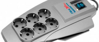
The presence of pulse currents in the network has a very harmful effect on the operation of modern household appliances, often saturated with electronics. If you do not use protective devices, electronic devices may fail, not to mention the quality of their operation. Of course, developers protect sensitive equipment with integrated noise suppression circuits, but additional external devices are often required, for example, uninterruptible power supplies, surge protectors (Fig. 1) and others.
Rice. 1. Protective pulse filters
Under radio frequency interference, most household appliances can operate normally. But radios, televisions and some medical devices are sensitive to them. However, modern digital radio electronics are quite well protected from such distortions.
Understanding the causes of distortions in the electrical network helps to solve equipment protection problems and consciously approach the selection of optimal noise suppression schemes.
K series filters
K series filters (Figure 7) are general purpose radio frequency power filters. They are intended for use in power circuits with high-resistance loads. Excellent for cases where the line is subject to pulsed, continuous and/or pulsating radio frequency interference. Models with the EK index meet the requirements of standards for use in portable devices and medical equipment.
Rice. 7. Appearance of K series network filters
Filters with index C are equipped with a choke between the housing and the ground wire. The main electrical parameters of the K series network filters are given in Table 3.
Table 3. Basic electrical parameters of K series network filters
| Name | Maximum leakage current, mA | Operating frequency range, MHz | Electrical insulation strength (within 1 minute), V | Rated voltage, V | Rated current, A | ||
| ~120 V 60 Hz | ~250 V 50 Hz | "conductor-body" | "conductor-conductor" | ||||
| VK | 0,5 | 1,0 | 0,1…30 | 2250 | 1450 | ~250 | 1…60 |
| E.K. | 0,21 | 0,36 | |||||
The electrical circuit of the K series filter is shown in Figure 8.
Rice. 8. Electrical circuit of the K series filter
The attenuation of the interference signal in dB when the line is loaded onto a 50 Ohm matching resistor is shown in Figure 9.
Rice. 9. Noise reduction with K series filters
Output smoothing filters
The same LC filters that were discussed above are used as smoothing output filters. However, in this case, such filters cannot be replaced with purchased ones, and the developer has to calculate them each time. The output smoothing filter allows you to reduce output voltage ripple to units of mV or even several hundred μV. Reducing the ripple amplitude to tens of µV is hardly possible, even if the number of output filter stages is increased.
The parasitic components of the filter components and the conductors of the printed circuit board will interfere with the reduction of ripple. In addition, due to switching frequency jitter, low-frequency components down to several Hz may appear in the output voltage spectrum. They, of course, cannot be suppressed by an anti-aliasing filter. Thus, if it is necessary to limit the output voltage ripple down to µV, an LDO regulator is installed in the power circuit after the smoothing filter.
Rice. 7. Anti-aliasing filter at the output of the boost converter
Let's consider the most common anti-aliasing filter configuration - the π-filter (or P-filter). The diagram of its connection to the boost converter circuit is shown in Fig. 7 [1]. The resonant frequency of this filter is determined from expression (4).
Unlike the EMI filter, the anti-aliasing filter is part of the feedback loop, so the cutoff frequency of the filter should not be less than 10–20% of the switching frequency. Otherwise, the stability of the system decreases due to a delay in the feedback loop, which leads to prolongation of transient processes, as well as to deterioration of stability due to a decrease in the phase margin. As with EMI filters, a damping circuit must be included in the anti-aliasing filter. In Fig. Figure 7 shows three possible options for damping chains.
Damping option 1 with the introduction of the RFILT resistor seems to be the simplest and most economical, but the introduction of this resistor weakens the effectiveness of the filter. In addition, the impedance of the parallel RL filter circuit is reduced. Damping option 2 is the most effective because this circuit improves the filter performance, but increases the cost due to the use of a ceramic capacitor. At first glance, it may seem that damping option 3 is the most effective. However, in this case the largest capacitor capacity is required. Consequently, the cost of the solution increases. In addition, since introducing this chain will reduce the feedback loop bandwidth, this option should be excluded from consideration.
For high-frequency converters with low output current, there is another non-trivial version of the smoothing filter - instead of a choke, a resistor is used in the filter. Let's consider a simple example where an RC filter is used as the output filter of a PoL converter with a switching frequency of 2 MHz and an output current of 20 mA. Let the resistor be 10 ohms and the capacitor be 1 µF. The cutoff frequency of this filter will be about 16 kHz; Taking into account the attenuation of 20 dB/decade, we find that ripples with a frequency of 2 MHz are attenuated by more than 100 times. However, you will have to put up with a voltage drop of 200 mV across the resistor.
Note that the calculation of filters is approximate and the calculated parameters must be checked by prototyping the filter together with the converter. The value of the filter capacitance is affected by the charge voltage, current pulsation frequency, and capacitance temperature. The inductance of the filter choke depends nonlinearly on the current. In addition, the converter will also affect the filter characteristics. These changes cannot be taken into account in practical calculations. Assistance in filter development is provided by proprietary CAD systems for calculating filters. For example, a scheme for calculating an anti-aliasing filter can be found in [1]. To calculate the EMI filter, you can use the tools of [2].
EMC series filters
Filters in this series (Figure 10) are compact and efficient two-stage RF power filters. They have a number of advantages: a high coefficient of attenuation of common-mode interference in the low-frequency region, a high coefficient of attenuation of anti-phase interference, and compact dimensions. The EMC series is focused on use in devices with switching power supplies.
Rice. 10. Appearance of EMC series filters
The main technical characteristics are given in Table 4.
Table 4. Basic electrical parameters of EMC series network filters
| Rated filter currents, A | Maximum leakage current, mA | Operating frequency range, MHz | Electrical insulation strength (within 1 minute), V | Rated voltage, V | Rated current, A | ||
| ~120 V 60 Hz for currents 3; 6; 10 A (15; 20 A) | ~250 V 50 Hz for currents 3; 6; 10 A (15; 20 A) | "conductor-body" | "conductor-conductor" | ||||
| 3; 6; 10 | 0,21 | 0,43 | 0,1…30 | 2250 | 1450 | ~250 | 3…30 |
| 15; 20; 30 | 0,73 | 1,52 | |||||
The electrical circuit of the EMC series filter is shown in Figure 11.
Rice. 11. Electrical diagram of two-stage filters of the EMC series
The attenuation of the interference signal in dB when the line is loaded onto a 50 Ohm matching resistor is shown in Figure 12.
Rice. 12. Attenuation of the interference signal with EMC series filters
EDP series filters
EDP series filters (Figure 13) are general purpose radio frequency filters for mounting on printed circuit boards. They have miniature dimensions and improved filtering of common mode noise at low cost and low leakage currents.
Rice. 13. Appearance of EDP series network filters
The main electrical parameters of the series network filters are presented in Table 5.
Table 5. Basic electrical parameters of EDP series network filters
| Maximum leakage current, mA | Operating frequency range, MHz | Electrical insulation strength (within 1 minute), V | Rated voltage, V | Rated current, A | ||
| ~120 V 60 Hz for currents 3; 6; 10 A (15; 20 A) | ~250 V 50 Hz for currents 3; 6; 10 A (15; 20 A) | "conductor-body" | "conductor-conductor" | |||
| 0,22 | 0,38 | 0,1…30 | 2250 | 1450 | ~250 | 1…10 |
The electrical circuit of the EDP series filter is shown in Figure 14.
Rice. 14. Electrical diagram of EDP series network filters
The attenuation of the interference signal in dB when the line is loaded onto a 50 Ohm matching resistor is shown in Figure 15.
Rice. 15. Attenuation of the interference signal with EMC series filters
FC series filters
A single-phase network filter for frequency converters is applicable in conditions of increased electromagnetic interference; it protects programmable logic controllers (PLCs) from negative influences from the AC supply network (Figure 16).
Rice. 16. Appearance of the FC series filter
The special design of the connecting terminals ensures safe connection and operation. The series has found wide application in the field of industrial automation. The main technical characteristics are given in Table 6.
Table 6. Basic electrical parameters of FC series network filters
| Filter type | Maximum leakage current, mA | Operating frequency range, MHz | Electrical insulation strength (within 1 minute), V | Rated voltage, V | Rated current, A | ||
| ~120 V 60 Hz for currents 3; 6; 10 A (15; 20 A) | ~250 V 50 Hz for currents 3; 6; 10 A (15; 20 A) | "conductor-body" | "conductor-conductor" | ||||
| No index | 3,80 | 6,70 | 0,01…30 | 2250 | 1450 | ~250 | 6…50 |
| Index B | 3,90 | 7,00 | |||||
The electrical circuit of the FC series filter is shown in Figure 17.
Rice. 17. Electrical diagram of FC series network filters
The attenuation of the interference signal in dB when the line is loaded onto a 50 Ohm matching resistor is shown in Figure 18.
Rice. 18. Attenuation of the interference signal with FC series filters
Design of network filters
And this is the circuit of the FN9222 filter with an IEC plug. It is available in a variety of versions including Medical (Type B), Snap-on Housing (Type S and S1), Surge Protector (Type Z) and Hot Inlet Connector Option (Type H1). The rated current, depending on the model, ranges from 1 to 20 A at a maximum temperature of + 50°C, and the leakage current under normal operating conditions is from 2 to 370 μA. Here are the insertion loss characteristics of this filter.
FN9222 filter circuit
In general, designing effective suppression filters is not an easy task. One of the key points is the choice of choke core material. It should be selected so that the impedance of the coupled coils in a given frequency range of common noise is as high as possible.
FN9222 Insertion Loss Characteristics
For this purpose, cores with high magnetic permeability, mainly ferrite, are used. This also reduces the parasitic capacitances of the coupled coils. This goal can be achieved by using an appropriate winding method. For example, single-layer coils have lower parasitic capacitance.
In the case of capacitors, the goal is to reduce parasitic inductance. This applies to internal and external inductances. In the latter case, this is achieved through the use of short wires. With regard to parasitic internal inductance, the type of capacitor is important - for example, ceramic capacitors are characterized by a lower value of this parameter than metallized ones.
AYO series filters
Compact three-phase low-current network filters are designed to filter network noise in three-phase general industrial networks with a neutral wire (Figure 19).
Rice. 19. Appearance of three-phase surge protector AYO series
A special feature of the AYO series power filters is the presence of filtering circuits for both power lines and neutral. They are characterized by low leakage currents and small overall dimensions, which allows their use in compact equipment. The filter provides effective noise suppression over a wide frequency range from 100 kHz. The main technical characteristics of the AYO series network filters are discussed in Table 7.
Table 7. Main technical characteristics of AYO series network filters
| Rated filter currents, A | Maximum leakage current, mA | Operating frequency range, MHz | Electrical insulation strength (within 1 minute), V | Rated voltage, V | Rated current, A | ||
| ~120 V 60 Hz for currents 3; 6; 10 A (15; 20 A) | ~250 V 50 Hz for currents 3; 6; 10 A (15; 20 A) | "conductor-body" | "conductor-conductor" | ||||
| 3; 6; 10 | 2,00 | 3,00 | 0,1…30 | 1500 | 1450 | ~440 | 3…20 |
| 20 | 3,50 | 5,50 | |||||
The electrical circuit of the AYO series filter is shown in Figure 20.
Rice. 20. Electrical diagram of a three-phase network filter AYO series
The attenuation of the interference signal in dB when the line is loaded onto a 50 Ohm matching resistor is shown in Figure 21.
Rice. 21. Attenuation of the interference signal with AYO series filters
When choosing a surge protector, you must take into account its operating voltage, rated current and operating frequency band. An indicator of efficiency is the noise attenuation coefficient as the ratio of the noise signal at the filter input to its output level.
The characteristic operating temperature for all series considered is within the range of -10...40°C. At ambient temperatures above 40°C, the maximum permissible operating current is calculated using the formula:
The COMPEL company maintains in stock the most popular models of the considered network filters produced by TE Connectivity. These positions and their brief characteristics are shown in Table 8.
Table 8. KOMPEL warehouse items
| Name | Series | Number of load phases | Nominal filter voltage, V | Rated current, A | Dimensions LxWxH, mm |
| 1EB1 | B | 1 | 250 | 1 | 57x64x17 |
| 5EB1 | B | 1 | 250 | 5 | 66x64x19 |
| 6ET1 | T | 1 | 250 | 6 | 90x85x46 |
| 10ET1 | T | 1 | 250 | 10 | 119x113x45 |
| 15VT1 | T | 1 | 250 | 15 | 138x100x55 |
| 15VT6 | T | 1 | 250 | 15 | 151x100x55 |
| 10VK6 | K | 1 | 250 | 10 | 87x71x29 |
| 20VK6 | K | 1 | 250 | 20 | 87x85x38 |
| 40VK6 | K | 1 | 250 | 40 | 135x106x38 |
| 3EMC1 | EMC | 1 | 250 | 3 | 85x70x29 |
| 10EMC1 | EMC | 1 | 250 | 10 | 97x85x38 |
| 15EMC1 | EMC | 1 | 250 | 15 | 126x113x45 |
| 20EMC1 | EMC | 1 | 250 | 20 | 126x113x45 |
| 3EDP | EDP | 1 | 250 | 3 | 36x31x24 |
| 6EDP | EDP | 1 | 250 | 6 | 36x31x24 |
| 10EDP | EDP | 1 | 250 | 10 | 36x31x24 |
| 6AYO1 | AYO | 3 | 440 | 6 | 85x85x38 |
| 10AYO1 | AYO | 3 | 440 | 10 | 85x85x38 |
| 20AYO1 | AYO | 3 | 440 | 20 | 85x85x38 |
| 6FC10 | F.C. | 1 | 250 | 6 | 116x78x45 |
| 12FC10 | F.C. | 1 | 250 | 12 | 139x100x55 |
| 16FC10 | F.C. | 1 | 250 | 16 | 139x100x55 |
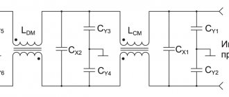
What elements does a surge protector consist of?
The anti-interference filters include a current-compensated choke. It is made by winding two identical windings on a toroidal core, which is characterized by high permeability.
Since the windings are wound in opposite directions, the differential noise cancels each other out. As a result, only the leakage inductance suppresses the residual currents. In the case of asymmetrical, the currents in the two windings diverge in the same direction.
The flux induced in the inductor core is the sum of the fluxes induced in both windings. Thus, the inductance of each winding suppresses the overall currents. This allows you to connect small capacitors between the phase conductors, neutral and ground.
The Cy capacitors suppress common noise but do not affect differential noise. The capacitance values Cy are selected so that their leakage current flowing through the protective conductor does not exceed the permissible values specified in the standards. But capacitors Cx only suppress differential noise.
Anti-interference filters are also equipped with a discharge resistor. It is connected in parallel with the filter capacitors to discharge them after disconnecting the device from the network.
Line filters can be divided into single-phase and three-phase. Three-phase anti-interference filters are available in versions without neutral wire (L1, L2, L3 + PE) or with neutral wire (L1, L2, L3, N + PE).
Literature
1.
2. Corcom Product Guide, General purpose RFI filters for high impedance loads at low current B Series, TE Connectivity, 1654001, 06/2011, p. 15
3. Corcom Product Guide, PC board mountable general purpose RFI filters EBP, EDP & EOP series, TE Connectivity, 1654001, 06/2011, p. 21
4. Corcom Product Guide, Compact and cost-effective dual stage RFI power line filters EMC Series, TE Connectivity, 1654001, 06/2011, p. 24
5. Corcom Product Guide, Single phase power line filter for frequency converters FC Series, 1654001, 06/2011, p. thirty
6. Corcom Product Guide, General purpose RFI power line filters - ideal for high-impedance loads K Series, 1654001, 06/2011, p. 49
7. Corcom Product Guide, High performance RFI power line filters for switching power supplies T Series, 1654001, 06/2011, p. 80
8. Corcom Product Guide, Compact low-current 3-phase WYE RFI filters AYO Series, 1654001, 06/2011, p. 111.
Obtaining technical information, ordering samples, delivery - e-mail
Network and signal EMI/RFI filters from TE Connectivity. From board to industrial installation
TE Connectivity is a world leader in the design and manufacture of surge protectors for effective suppression of electromagnetic and radio frequency interference in electronics and industrial applications. The model range includes more than 70 series of devices for filtering both power circuits from external and internal sources, and signal circuits in a wide range of applications.
The filters have the following design options: miniature for installation on a printed circuit board; cabinets of various sizes and types of connection of supply lines and load lines; in the form of ready-made power connectors and communication connectors for network and telephone equipment; industrial, made in the form of ready-made industrial cabinets.
Surge filters are produced for AC and DC applications, single- and three-phase networks, covering the range of operating currents 1...1200 A and voltages 120/250/480 VAC, 48...130 VDC. All devices are characterized by a low voltage drop - no more than 1% of the operating voltage. The leakage current, depending on the power and design of the filter, is 0.2...8.0 mA. The average frequency range for the series is 10 kHz...30 MHz. AQ series is designed for a wider frequency range: 10 kHz...1 GHz. Expanding the applications of its products, TE Connectivity produces filters for low and high impedance load circuits. For example, high impedance filters of the EP, H, Q, R and V series for low impedance loads and low impedance filters of the B, EC, ED, EF, G, K, N, Q, S, SK, T, W, X, Y and Z series for high impedance loads.
Communication connectors with built-in signal filters are available in shielded, paired and low-profile designs.
Each filter produced by TE Connectivity undergoes double testing: at the assembly stage and already in the form of a finished product. All products comply with international quality and safety standards.
•••