4.1.3. Types of voltmeter inputs.
There are two types of voltmeter input:
— open
– the voltmeter responds to the entire signal U(t) (DC and AC components);
— closed
— the voltmeter reacts only to the alternating component of the signal;
Figure 4.3
Figure 4.2
A voltmeter with a closed input (Figure 4.3) differs from a voltmeter with an open input (Figure 4.2) in that it has an isolation capacitor in the input circuit, which does not allow the DC component of the signal to pass through. Figure 4.4 shows the timing diagrams of the signal U ( t )
, and its variable component.
A voltmeter with a closed input measures only the alternating component of the signal. To determine the voltage parameters of the variable component of the signal , ,
,
you need to substitute in formulas 4.1 ¸ 4.4 the analytical expression for the variable component of the signal, which can be easily found by subtracting the average voltage value
U avg
:
;
(4.11)
Basic units in the SI system Table 1.1
| Magnitude | length | weight | time | email current | thermodyne temperature | the power of light | Quantity of substance |
| Name | meter | kilogram | second | ampere | kelvin | candela | mole |
| designation, Russian international | m | kg | With | A | TO | St. | mole |
| m | kg | s | A | K | CD | mol |
Appendix 1.2. Multiples and submultiples
4.1.4. On the calibration of electronic voltmeters.
From the above it follows that to measure different signal parameters, various voltmeters are used, which respond either to the peak, or to the average-rectified, or to the root-mean-square voltage value of the measured signal. The type of parameter being measured is determined by the type of converter used in the voltmeter. When measuring the peak value, use a voltmeter with a peak converter, to measure the average rectified value, use a voltmeter with an average-rectified value converter, and for the root-mean-square value, use a voltmeter with a quadratic converter. However, the scales of most electronic AC voltmeters are usually calibrated in RMS voltage values of a harmonic signal (sinusoidal waveform). In this case, only the readings of a voltmeter with an RMS value converter are equal to the measured parameter for any form of the measured signal. The readings of voltmeters with other types of converters are determined by the relationship:
UVi = C gr
i × Ux
;
(4.12)
where UVi
is
the reading of the corresponding voltmeter;
C gr i
is the calibration coefficient of this voltmeter;
Ux
is the voltage parameter to which this voltmeter responds.
Table 4.2
№
p/p
Devices used
In every home, the electricity meter is in a state of constant measurement of alternating voltage, but it is extremely rare that this data is displayed anywhere. Some of them are connected directly, others through instrument transformers.
For practical purposes, the following can be used to measure voltage levels:
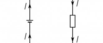
- Voltmeters;
- Multimeters
- Oscilloscopes.
A voltmeter is a device for testing potential differences. In practice, you can find both digital and analog voltmeters, in which the measured voltage is displayed on the display or by deflecting the arrow on the dial, respectively.
Important parameters when choosing both an electronic and a pointer voltmeter are units of measurement (mV, V, kV), operating range and accuracy class. However, the scope of their application is limited and is used, most often, for laboratory research, since for domestic and industrial needs it is impractical to maintain one device for measuring one electrical quantity.
A multimeter or digital tester is a more versatile device that can work with several parameters: electric current, resistance, frequency, temperature, voltage, etc. To measure voltage, the multimeter switches to voltmeter mode, the probes are connected to the appropriate connectors. Structurally, there are both digital and analogue models, in some of them you can switch the measurement range, select the type of current, in other multimeters all these values can be selected automatically.
An oscilloscope is a rather complex instrument for measuring potential differences, since it displays a curve of the measured value on a digital or analog display. In this case, you can stretch or shorten the frequency range to consider the shape of the pulse voltages, pulse duration, rises and dips in the function curve. Therefore, an oscilloscope for measuring voltage is used in electrical circuits and high-precision devices, in the manufacture and testing of radio components, etc. Few people keep an oscilloscope at home due to the high cost and complexity of operations.
4.1.5. Methodological error when measuring voltage.
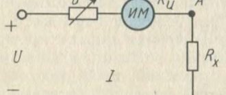
When measuring voltage, a voltmeter is connected to the circuit under test. If the voltmeter has an infinitely large input resistance, then the operating mode of the circuit under study is not disrupted and the voltmeter reading will correctly reflect the voltage parameters of the circuit under study. Real voltmeters have a finite input resistance value Z V
, so the reading of a real voltmeter will differ from the ideal one.
The difference between the readings of real and ideal voltmeters is the methodological error in measuring voltage with a voltmeter. Figure 4.5 shows the equivalent circuit for measuring voltage with a real voltmeter V.
Multiples Table 1.2
| Factor | 1018 | 1015 | 1012 | 109 | 106 | 103 | 102 | 101 |
| Name | exa | peta | tera | giga | mega | kilo | hecto | soundboard |
| Designation, Russian international | E | P | T | G | M | To | G | Yes |
| E | P | T | G | M | k | h | da |
Equivalent circuit
Z i
– complex internal resistance of the signal source;
Z V
– complex input resistance of the voltmeter.
The circuit under study is represented by an equivalent source with internal resistance Z i
and EMF
E.
An ideal voltmeter has Z V
®
¥
.
In this case, the voltmeter reading is equal to the emf of the
source E.
UV voltmeter reading
equal to the voltage drop across the resistance
Z V
;
(4.11)
.
From here you can find the methodological error in measuring voltage:
D E
= UV - E
methodological error can be either positive or negative, since Z i
may be inductive in nature, and
ZV
may be capacitive, so resonance is possible at high frequencies and then
UV > E.
Relative error:
Explanation in simple words
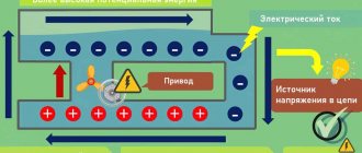
Electrical voltage U is the very reason that “forces” electric current I to flow. Electrical voltage always occurs when the charges are separated from each other, that is, all the negative charges are on one side, and all the positive charges are on the other. If you connect these two sides with an electrically conductive material, an electric current will flow.
The generally accepted definition of the term "electrical voltage".
Electrical voltage (or simply voltage) is the potential difference between two points in an electric field. It is the driving force for electric charge.
Potential in an electric field is the energy of a charged body, independent of its electric charge. For clarification, you can look at the comparison with the water circuit just below in the article.
There is another definition (from an 8th grade physics textbook):
Voltage is a physical quantity that characterizes an electric field. The electric voltage between two points of the electric field is numerically equal to the work done when a charge of 1 C is transferred between them by the forces of the electric field.
Comparison using a water flow model.
A good analogy to help you think about electrical voltage and potential is a water circuit. In this design, you have two pools at different heights that are connected by a pipe. In this pipe, water can flow from the upper pool to the lower one. The water is then pumped back to the upper basin using a pump as shown in the picture below.
Electrical Voltage - Comparison Using Water Flow Model
In your thinking, you can now easily compare a pump with a source of electrical voltage. In addition, the flow of water can be compared to electric current. The pump transports water from the lower pool to the upper one. From there it flows independently back to the lower pool. In this example, the pump is the flow driver. The greater the difference in height, the stronger the flow. The decisive factor is the potential energy of the upper basin. You can compare the difference in energy between the two pools with the difference in electrical potential. Simply put, a greater difference in height equals a greater electrical voltage.
Alternator
The bulk of the world's electricity is currently generated by alternating current generators, which create harmonic oscillations.
- An alternating current generator
is an electrical device designed to convert mechanical energy into alternating current energy.
The induction emf of the generator changes according to a sinusoidal law
\(e={\rm E}_{m} \cdot \sin \omega \cdot t,\)
where \({\rm E}_{m} =B\cdot S\cdot \omega\) is the amplitude (maximum) value of the EMF. When connected to the terminals of the load frame with resistance R
, alternating current will pass through it. According to Ohm's law for a section of a circuit, the current in the load
\(i=\dfrac{e}{R} =\dfrac{B \cdot S \cdot \omega }{R} \cdot \sin \omega \cdot t = I_{m} \cdot \sin \omega \cdot t,\)
where \(I_{m} = \dfrac{B\cdot S\cdot \omega }{R}\) is the amplitude value of the current.
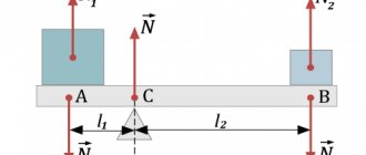
The main parts of the generator are (Fig. 1):
- inductor
- an electromagnet or permanent magnet that creates a magnetic field; - armature
- a winding in which an alternating EMF is induced; - a commutator with brushes
is a device by which current is removed from or supplied to rotating parts.
Rice.
1 The stationary part of the generator is called the stator
, and the movable one is
the rotor
. Depending on the design of the generator, its armature can be either a rotor or a stator. When receiving high-power alternating currents, the armature is usually made motionless in order to simplify the current transmission circuit to the industrial network.
In modern hydroelectric power plants, water rotates the shaft of an electric generator at a frequency of 1-2 revolutions per second. Thus, if the generator armature had only one frame (winding), then an alternating current with a frequency of 1-2 Hz would be obtained. Therefore, to obtain alternating current with an industrial frequency of 50 Hz, the armature must contain several windings that allow increasing the frequency of the generated current. For steam turbines, the rotor of which rotates very quickly, an armature with one winding is used. In this case, the rotor rotation frequency coincides with the alternating current frequency, i.e. the rotor should make 50 rps.
Powerful generators produce a voltage of 15-20 kV and have an efficiency of 97-98%.
From the history
. Initially, Faraday detected only a barely noticeable current in the coil when a magnet moved near it. "What's the use of this?" - they asked him. Faraday replied: “What use can a newborn baby have?” A little more than half a century has passed and, as the American physicist R. Feynman said, “the useless newborn turned into a miracle hero and changed the face of the Earth in a way that his proud father could not even imagine.”
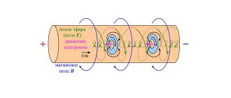
*Operating principle
The operating principle of an alternating current generator is based on the phenomenon of electromagnetic induction.
Let a conducting frame of area S
rotates with an angular velocity ω around an axis located in its plane perpendicular to a uniform magnetic field with induction \(\vec{B}\) (see Fig. 1).
With uniform rotation of the frame, the angle α between the directions of the magnetic field induction vector \(\vec{B}\) and the normal to the plane of the frame \(\vec{n}\) changes with time according to a linear law. If at time t
= 0 angle α0 = 0 (see Fig. 1), then
\(\alpha = \omega \cdot t = 2\pi \cdot \nu \cdot t,\)
where ω is the angular velocity of rotation of the frame, ν is the frequency of its rotation.
In this case, the magnetic flux passing through the frame will change as follows
\(\Phi \left(t\right)=B\cdot S\cdot \cos \alpha =B\cdot S\cdot \cos \omega \cdot t.\)
Then, according to Faraday's law, an induced emf is induced
\(e=-\Phi '(t)=B\cdot S\cdot \omega \cdot \sin \omega \cdot t = {\rm E}_{m} \cdot \sin \omega \cdot t.\ )
We emphasize that the current in the circuit flows in one direction during half a turn of the frame, and then changes direction to the opposite, which also remains unchanged during the next half turn.