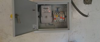
Installing an electrical panel with your own hands with minimal knowledge about wiring and electricity is a very real task. You just need to carefully and thoroughly study the instructions for connecting the machines in the switchgear and do everything strictly in accordance with it.
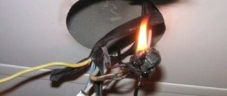
The worst thing that can happen if the wires are wired incorrectly is a short circuit, which can lead to the most undesirable consequences. In theory, a common circuit breaker, which should be in the circuit earlier than the mounted panel, should eliminate these consequences.
If we are talking about a floor panel in a city residential building or an individual one located in an apartment, then a circuit breaker will be a faithful protector. It can be a three-phase switch or a single-phase one - it all depends on the wiring diagram in the house.
Everything becomes more complicated when working with the wiring of a private house. In this situation, you must be protected by a machine located in the transformer booth from which the line is extended to you. Sometimes there are intermediate transformers that can be seen on power transmission towers in rural areas. They are often supplemented with protective fuses that prevent the transformer from failing when accidents occur on the line.
But if you know exactly the rules for connecting the machine in the control panel, you can avoid emergency situations. In this case, you have the only unpleasant and somewhat dangerous job - connecting the assembled device “hot”, that is, to live wires. Or you will need to call an electrician who will remove the voltage from the line during installation.
But first, let's look at the installation and connection stages.
Copper ground bus
The copper-based grounding bus refers to conductors with low resistance values.
The standard element is fixed to the body of the electrical panel, and also easily withstands thermal loads and high voltage during a short circuit. One of the most popular options is a grounding copper strip, made using high-quality electrical copper of the “M-1” grade.
Copper grounding bar
The protective element is manufactured in accordance with GOST 434-78, and is characterized by a high level of alloy purity with a solid metal content of 99% or more.
Due to the high quality of the source material, the copper busbar is designed for operation in operating temperatures ranging from minus 55°C to plus 280°C, with a maximum operating voltage of 1000 W.
Established standards regulate the marking of copper grounding bars with mandatory indication of thickness, width and length.
Tire installation option
Copper grounding bars can be used not only indoors, but also outdoors, due to the following performance characteristics:
- high level of thermal conductivity;
- high level of electrical conductivity;
- low resistivity values;
- resistance to corrosive changes.
When installed externally, copper grounding bars provide effective lightning protection, so they are often mounted on lightning rods.
It is very important to install copper ground bars in regions where there is extremely frequent and high lightning activity.
Design features
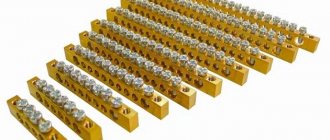
First, let's look at the design of the comb. The product consists of a copper plate placed in plastic insulation that does not support combustion. Special leads extend from this plate, thanks to which the machines in the panel are connected. The number of plates corresponds to the number of poles.
Please note that there are combs with pitches of 18 and 27 mm. The first ones are intended for switching AVs with a width equal to one module. Accordingly, 27 mm is a width of 1.5 modules
Pay attention to this point when choosing a distribution bus for your own conditions!
Based on the number of poles, connecting busbars are divided into single-pole, two-pole, three-pole and four-pole. Each design option has its own purpose. For example, a single-pole comb is used to connect a single-phase circuit breaker, and a four-pole comb, respectively, is used to install three-phase RCDs with 4 poles (three phases and zero).
The number of taps can be from 12 to 60, so the use of combs to connect two electrical machines is not a rational solution. It is advisable to use a distribution bus when assembling large panels.
The taps themselves can be pin (marked pin) or fork (fork). The former are used much more often, because Fork outlets are not suitable for all machines; they require a special clamp.
The last design feature that I would like to talk about is the cross-section of the bends. As a rule, taps are made with a cross-section of 16 mm2, which is quite enough to withstand a current load of 63 A.
Typical installation mistakes
Most often, when installing electrical wiring, and in particular connecting a machine, the following mistakes are made:
- The power wire is inserted from below. Despite the fact that this electrical installation option is not prohibited by the PUE rules, we still do not recommend connecting the circuit breaker from below, especially since even on the front panel of the case there is a diagram in which the installation location of the fixed contact is at the top (as shown in the photo below) .
- The contacts are clamped too tightly with the fixing screw. This should not be allowed, because as a result, you can not only damage the cable core, but also deform the body of the product.
- The conductors are not connected correctly. A prerequisite is that the phase must be connected under the phase, zero under zero (if a two-pole switch is used). We immediately recommend that you familiarize yourself with the material: color coding of wires.
- Instead of one two-pole circuit breaker, two single-pole circuit breakers are used. This is strictly prohibited, because... phase and zero must be disconnected at the same time.
- When fixing the core, insulation gets into the seat. Be sure to strip the wire as much as required by the model data sheet. If you press down on the insulation with a screw, the contact of the conductor will weaken, as a result of which the core will heat up and further adverse consequences will occur. For this task, we recommend using a special tool for removing insulation.
- The choice of circuit breaker is incorrect; in particular, the product is not able to withstand the incoming loads. In this case, first you need to correctly calculate the cable cross-section and, according to the calculated characteristics, select the appropriate model.
- When calculating a suitable circuit breaker, the value is rounded up. For example, you calculated that the current load on the product is 19 Amperes. According to the simplest logic, novice electricians go to the store and purchase a device of the closest value for connection - 20 Amperes. This is a huge mistake, because... the calculated value is nominal, and it turns out that the protection will operate when the wiring is slightly overloaded. It is better to purchase a switch with a rating of 16 Amps, so the electrical wiring will last longer.
Another important point on which there is a lot of discussion is whether it is possible to connect the machine in front of the electricity meter or is this done only after it? The answer is that it is possible, and even necessary, the main thing is to buy a special box, which is sealed by energy sales representatives. Installing an input machine in front of the electric meter will allow you to safely replace the electricity control device both in a private house and in an apartment.
Here, in fact, are the rules for installing and connecting an electrical machine with your own hands. Now let's move on to the main topic of the article.
Metals used in tire production
Depending on the purpose and required operating parameters, the following can be used for the manufacture of conductors:
- copper;
- aluminum;
- steel;
- steel-aluminum - a steel core covered with a layer of aluminum wires.
The advantages of aluminum tires include anti-corrosion resistance, excellent electrical conductivity, low weight and reasonable cost. For their manufacture, low-alloy aluminum alloys with a low content of silicon and magnesium are used to improve the ductility and strength of the metal.
Copper buses with a copper content of up to 99% are in no way inferior to aluminum ones, but are less widespread due to their relatively high cost.
Zero bus
Zero tire on DIN rail
The connection of grounding and neutral working conductors is carried out using a zero bus. Its design consists of a conductive core and a plastic base, which is mounted on a DIN rail. The core is made of special electrical copper or brass. The design of the conductive element has holes and clamping bolts. Their presence allows for accurate and safe cabling in switchgear units. Models of zero busbars are made in different lengths, which allows you to make the required number of mounting holes in the core. Their main area of application is AC or DC networks designed for operating voltages up to 400V.
Thanks to the use of a zero bus it will be possible to:
- increase the efficiency of the automatic protective devices used;
- create simultaneously several points for connecting loads to the neutral conductor;
- carefully and safely separate neutral and working conductors;
- perform visible grounding using a plastic device with a cover to protect the terminals;
- install a single circuit from the grounding point to each load.
Installation of the zero bus is carried out directly inside the electrical panel or on a metal rail using a bolted connection. There are open and closed installation methods. The first option is provided for electrical cabinets with a closed structure, which prevents unauthorized persons from accessing the internal contents. Closed installation is optimal for networks to which expensive, energy-intensive equipment is connected - machines and mechanisms, power tools, etc.
Design features
Upon closer examination of the design, you will notice that it consists of a conductive core and a base made of plastic, which is designed for installation on a DIN rail.
The photo shows the appearance of the NS:
The current-carrying core contains holes and clamping bolts for fixing the conductors in it, as well as for neat and safe wiring of conductors N inside the switchgear. NS differ from each other in both the installation method (housing) and the number of mounting holes, respectively, in length.
To ensure a high-quality connection, as well as simplify further maintenance, the bus is made of a single conductive element of sufficient size made of electrical copper or brass. With a different number of bolt terminals to which neutral (N) conductors are connected.
A distinction is made between ground buses in a housing and grounding buses without a housing; the externally conductive elements are identical. The neutral bus is made in a housing or an insulator is installed. For the correct functioning of differential protection devices, it is necessary to connect them correctly, and to separate the conductors N from PE in the distribution board. In the case of a metal shield, this can only be done by isolating the neutral conductor from the housing.
TN-CS system in your home
As described above, this is easy to determine - count the number of power wires in the shield, there should be 5. Just be sure to make sure that the zero bus is disconnected from the housing!
Grounding in the apartment in this case is done as follows:
- ⚡
the phase of your power cable is connected to the old place where the old wiring was previously connected. It is not recommended to switch to another phase on your own. As a rule, the load in the entrance is already distributed, and your initiative may affect the voltage imbalance; - ⚡
The zero core is connected to the zero bus. It must be disconnected from the body and not have any connection with it; - ⚡
The ground wire is connected to the housing. Do not connect your wire under bolts where neighboring apartments are already connected. Select a separate mounting location.
If your home has a modern TN-S system, the connection mechanism is the same.
Installation Rules
Installation of the simplest terminal to the panel is carried out in a closed or open way. The first option prevents malicious damage to the bus of powerful or important devices, the second method is applicable if there is no risk of damage to the device. Zero blocks with screw connections are fixed to the distribution panel on a DIN rail; additional insulation for grounding is not provided.
The cross-section of neutral and phase conductors is the same. A similar requirement applies to tire parameters: the actual cross-section is considered to be the size of the thinnest sections. When combining a group of ground and neutral conductors, end consumers, after dividing the “PEN” input, are connected to different buses: PE and N.
Zero bus: types, what it is needed for
As is known, the power supply system for the end consumer is built according to the schemes recommended by the Electrical Installation Rules (PUE). A power cable is supplied to the facility, and further wiring occurs in the distribution panel.
For ease of installation and organization of power supply lines, inputs with different values are combined into contact groups.
A bus with a phase, a zero bus is a contact block in which there is the ability to reliably connect several conductors to power electrical installations.
Requirements for the zero bus
For a group network, the bus must be a single conductor, without the possibility of switching between its parts. The resistance should be the same along the entire length. Within one group line, it is allowed to combine conductors PE (protective grounding) and N (working zero). Moreover, after dividing the PEN input into PE and N buses, end consumers are connected to different buses. Important! Using one bus to connect the working zero and grounding is prohibited! This is a fundamental issue, it is necessary to understand the difference between separation and combination of PE and N. From the moment of separation, the ground and neutral lines can be laid in the same power cable, but the conductors must be insulated. Regardless of the connection method (three-phase or single-phase), the cross-section of the neutral conductor must correspond to the cross-section of any of the phase conductors. The same requirement applies to the cross-section of the tire itself. The cross-section of the connecting wires from the bus to the final electrical installation cannot be higher than the cross-section of the input power wire. If the bus is a structure with holes for connecting conductors, the actual cross-section is considered to be the geometric parameters in the thinnest part. There are no requirements for the mandatory production of a zero working tire from a specific metal
However, in practice, copper or brass is used. When calculating the cross-section of aluminum busbars in relation to copper busbars, a coefficient of 1.52 is applied.
For convenience, we will consider a single-phase circuit, which is used in most apartments in multi-storey buildings. Two main lines: phase and zero, are always present. They are inserted into the meter (electricity meter), and at the output they become available for further wiring. Depending on the system used, either only a zero bus or a zero and ground bus can be installed.
How to prevent critical heating of the zero?
Since on the scale of an apartment the influence of higher harmonics is insignificant, we will immediately move on to the problem of poor electrical contacts. If you find a problem area in the apartment panel where the electrical connection is heating up, then first of all turn off the input circuit breaker and make sure that after that the current does not flow. The best way to test is to use a combination of a voltage probe and a multimeter set to AC current.
Once you are sure the power is off, loosen the offending terminal (usually a screw terminal) to remove the wire. Clean it, as well as the clamp. If the panel wiring is made with stranded copper wire, then its ends must be tinned or crimped. After this, you can collect the contact. It should be taken into account that “pinching” the wire with a screw connection is as undesirable as a weak clamp.
Direct contact of copper and aluminum is unacceptable, since these materials form a galvanic couple, as a result of which the electrical resistance of such a connection will increase quite quickly.
If the installation was carried out using thin wires, then it is advisable to replace them. How to choose the right cross section depending on the load current is described on our website.
Benefits of using busbar trunking
An electrical bus is more convenient to use than a group of wires
The use of busbars in electrics instead of cable products provides significant savings in material, energy and labor resources:
- Installation takes 2 times less time than cable laying.
- Service life – up to 30 years without the need for complex maintenance.
- The flexible configuration allows for high-quality and safe installation of the network, depending on the route it runs.
- The busbar has a more aesthetic appearance than group wiring.
- Shielding the conductor eliminates the impact of the electromagnetic field on nearby office equipment.
- The design is fireproof and meets safety requirements for IP55 protection level.
More details about the appointment
Using a grounding zero bus in the wiring system allows you to solve many important issues:
- Creation of several points to share the total load from the main input to the neutral conductor.
- “Opening” the grounding mechanism through the use of a transparent cover in the design that protects the terminals.
- Increasing the efficiency and performance of automatic protection devices.
- Ensuring line continuity from direct grounding to the output point.
- Saving space in the panel, since there will be no need to place several single tires.
- Separation of neutral and phase wires.
In general, the zero bus allows you to raise the security of the network to a qualitatively new level, however, its use and connection must be as competent as possible, therefore special requirements are imposed on the installation of this element of the electrical network.
A little about mechanics
Having dealt with the question of how to properly connect the machine, the question of how to install it remained unexamined. If you are planning a new shield, then most likely the first thing you will have to do is install a DIN rail there.
Each modern circuit breaker has a special clamp for mounting on this very rail. The feed-through contact, which is used for the grounding conductor, has the same fastening. By the way, the latch of such a grounding conductor is not made as a separate plastic element, but as a springy part of the housing. This is very convenient, as there is no risk of losing a small but very important detail.
If it is not possible to find a pass-through element, the grounding connection can also be made by twisting. However, to be sure, you can tin the wires with a soldering iron and put heat-shrink tubing on them as insulation. This is completely justified. Do not forget that phase and neutral conductors still “walk” along the shields. If you don't have heat shrink tubing, you can use insulating tape. This will be no less protection against any surprises.
By the way, it is strictly worth remembering that the connection and even grounding cannot be done in such a way as to twist copper and aluminum wires together. These two metals form a galvanic couple, which leads to their oxidation and disruption of conductivity between them. If it turns out that it is not possible to connect them through a pass-through element or a block with steel contacts, then you can tin each of the wires and carefully solder the connection.
Characteristics
When choosing the necessary zero buses, it is worth presenting clear requirements for the design. The main thing is the cross-section of the wire. Guided by the clear rule “the cross-section of the wire does not exceed the cross-section of the main grounding bus,” you can provide high-quality power supply and save money on maintenance in the future.
The characteristics of the zero bus vary depending on the type of installation. There are two types of devices according to the distribution scheme that meets the requirements of the PUE:
In the first case, a grounded bus, which is a tightly grounded neutral, in which connection to the protective ground is provided exclusively at this point. Further, only two busbars are inserted into the shield along the insulated conductors. This scheme is considered the safest, since the neutral and grounding buses are separated directly at the entrance of the device into the room.
The second option presents an outdated but popular TN-C type circuit. In this case, the grounding is not represented by a separate conductor, but in the panel itself there is only a zero bus. Here, too, you cannot connect ground and zero. Therefore, here the concept of “earth” in its usual representation is not present.
Grounding systems in apartment buildings
Old-built houses have a grounding system - TN-C. The floor electrical panels in them are not grounded, but grounded. The shield includes 3 phases and a neutral wire, which is mounted on the shield body. There are four conductors in total.
In modern houses, the system used is TN-CS. Here, not four, but five power wires enter the shield. Three phase, neutral and separate protective conductor. It is the protective conductor that is connected to the shield body. The zero has a separate bus, not connected to the body. There is an even more modern TN-S system. Here, five conductors, separately from each other, are laid directly from the transformer substation to the residential building.
Briefly about the design and operating principle
If you look closely at the photo of the zero bus, you can see a conductor made of electrical copper or brass on a plastic base. Each mini busbar is separated from its neighbor by a transparent plate, ensuring safety and insulation.
The holes and clamping bolts in the structure are designed to secure conductors and route them safely, and the device is fixed to a DIN rail using a plastic housing.
The length of the product depends on the number of mounting holes available, however, despite the difference in the clamping bolts, the tire is always monolithic, which simplifies maintenance and increases the safety and reliability of fastenings.
Also, grounding buses differ in the presence of the housing:
Zero tires with a body inside do not differ from their “bare” counterparts, but are externally enclosed in a special plastic block, which in most cases is made of opaque white plastic on three sides, and with a transparent bluish cover on the front side.
It is easy to identify this grounding device in the shield not only by its oblong shape, but also by the obligatory presence on the body or base of a blue or light blue color - a clear indicator of the zero type of the electrical network element.
Secrets and standards of installation
When installing the zero bus, one of several possible types of installation can be used (the appropriate one is prescribed in the instructions):
- On an insulator, screwed in the center or along the edges;
- Screw;
- On DIN rail;
- On G-rail.
In turn, zero bus insulators can be absent or can be case-type, “rack” type, combined, single or double corner (“leg” type).
- Familiarize yourself with the appropriate panel connection diagram, find the zero bus in the image (the icon repeats the general appearance of the device marked “N”).
- De-energize the electrical panel by unscrewing all existing plugs or placing the circuit breakers in the inoperative position.
- Check that there is no voltage by holding an indicator screwdriver or multimeter to the input conductors.
- Determine the location for placing the bus depending on its design features (if fixation to special strips is provided, then install the necessary ones in the panel; if not, fasten them through insulators to a free place).
- Install the strip on the DIN or G using special clamps, or directly into the panel using a screw type of installation from the center or sides (where the insulator is located).
- Check the reliability of the fastenings by trying to “loose” the installed structure.
- Connect the conductor coming from the residual current device to one of the busbar clamping bolts.
- If the circuit has two or more protective connection devices, then each of them is connected in series to the bus.
- Connect the neutral conductors coming from the circuit breakers of each branch of the network to the corresponding terminal of the neutral protective device.
- Connect the common “zero” of the network to the outer terminal on the zero bus.
- Check the correctness and quality of all connections made.
- Turn on the electricity supply.
During work, it is important to follow the safety rules:
- Install only when there is no current in the conductors;
- Use special clamps, terminals, and not homemade “twists”;
- Ensure good contact of the wires, if necessary, trim and strip their ends;
- Do not allow wires to overlap, twist, break or bend;
- Do not neglect marking conductors in any available way (color, signature, signs).
The zero line is an integral part of any electrical network, so it is important to properly organize its functioning inside the panel. The zero bus will provide order and the possibility of sequential connection of all contacts to ensure safe, comfortable and complete use of electricity.
Specifications
The grounding bus must be installed inside the electrical panel and connected to the current grounding circuit.
Due to its basic technical characteristics, such an element is used as a conductor between the grounding system and the plug part of the technical installation. Inside the input devices, as a rule, grounding buses of the “PE” type are used.
Ground bus with ground wires
In such conditions, the grounding conductor must have the appropriate cross-section:
- copper conductors - 1.1 cm or more;
- aluminum conductors - about 1.7 cm or more;
- steel conductors - 7.5 cm or more.
The cross-sectional parameters of the installed grounding bus must correspond to the parameters of the conductor.
| Tire type | Conductor cross-section | Current | Number of holes for fasteners | Number of clamps | Dimensions |
| RE 6/1 | 1.5-16 mm2 | 63 A | 1 | 6 | 6x9x46 mm |
| RE 8/1 | 1.5-16 mm2 | 63 A | 1 | 8 | 6x9x58 mm |
| RE 8/2 | 1.5-16 mm2 | 63 A | 2 | 8 | 6x9x64 mm |
| RE 10/2 | 1.5-16 mm2 | 63 A | 1 | 10 | 6x9x70 mm |
| RE 10/1 | 1.5-16 mm2 | 63 A | 2 | 10 | 6x9x76 mm |
| RE 12/1 | 1.5-16 mm2 | 63 A | 1 | 12 | 6x9x82 mm |
| RE 12/2 | 1.5-16 mm2 | 63 A | 2 | 12 | 6x9x89 mm |
| RE 14/1 | 1.5-16 mm2 | 63 A | 1 | 14 | 6x9x95 mm |
| RE 14/2 | 1.5-16 mm2 | 63 A | 2 | 14 | 6x9x102 mm |
| RE 16/1 | 1.5-16 mm2 | 63 A | 1 | 16 | 6x9x107 mm |
| RE 16/2 | 1.5-16 mm2 | 63 A | 2 | 16 | 6x9x114 mm |
| RE 18/1 | 1.5-16 mm2 | 63 A | 1 | 18 | 6x9x119 mm |
| RE 18/2 | 1.5-16 mm2 | 63 A | 2 | 18 | 6x9x126 mm |
| RE 20/1 | 1.5-16 mm2 | 63 A | 1 | 20 | 6x9x132 mm |
| RE 20/2 | 1.5-16 mm2 | 63 A | 2 | 20 | 6x9x138 mm |
| RE 24/2 | 1.5-16 mm2 | 63 A | 2 | 24 | 6x9x163 mm |
The grounding bus can be of the zero working type “N” and the protective type “PE”, but the installation of such a device must be carried out by specialists, which will make the operation not only durable, but also safe.
Conclusion
The main distinguishing feature of “zero” and “ground” is their purpose. “Zero” together with the phase is intended to power electrical appliances, and “ground” is to protect people and animals from electric shock if a breakdown occurs. The working “zero” can be used as a “ground” if the conditions of PUE 1.7.83 are not violated. We recommend laying the wiring immediately with a grounding conductor, which eliminates the need to use the “zero” for other purposes.
Test your electrical knowledge:
- Why is there 220 V between phase and zero, and 380 V between phases?
- Why is the voltage in the networks 110 V in the USA, and 220 V in Russia?
Installation Rules
Installation of the NS is possible both on a special rail and in an electrical panel. Installation options are available in both closed and open ways. The open method is perfect for a cabinet that will be closed to unauthorized persons. The closed version is used in situations where equipment is used that is connected to very important elements. An example is a power socket for various electrical tools.
The video below clearly shows how to install the NS on a DIN rail and how to fix it more reliably:
So we looked at the structure and purpose of the zero bus. We hope the information was useful and interesting for you!
You probably don't know:
- What is GZSh in electrical engineering?
- Why do you need a cross module?
- What is the danger of a broken neutral wire?
Why do you need a partner?
As you know, when working with electricity you need to take as many safety precautions as possible. Another practical advice from experts is to repair electrical wires with a partner.
The person chosen for this role may well not understand anything about electrical circuits. However, he must clearly know what to do if someone comes under voltage: pull the person by the clothes, without touching his body, away from the live wire.
It is advisable to first unbutton the jacket that you are wearing to protect your hands before making connections in the electrical panel. This is vital. The fact is that a free part is formed on the back, by which a person can be pulled away in the event of an electric shock. It will be convenient for your partner to grab onto it. Your partner should also remember how to call an ambulance or emergency services.
The help of a partner can be invaluable when the shield is located high. He will be able to give or receive tools. This way, you won’t have to constantly go down and get up again from a stool or stepladder.
It is better to make two zero tires in the shield!
28 Jan 2022 Assembly of shields
Hello everyone, today is an article on practical experience in assembling electrical panels from experienced electrician Sergei Panagushin from Izhevsk. We will talk about such a nuance as installing zero busbars in the shield; Sergey will tell you how best to do it so that the contact of the busbar with the wires is the best.
If it’s not difficult for you, vote for this article by Sergei here - https://vk.com/wall-125051812_548
Just like it.
So, word from Sergei:
Hello dear reader! In today’s article I would like to share a couple of tricks that can be used when installing automatic machines and zero tires in the dashboard.
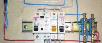
So: it is best to install tires not one at a time, but two at a time, as shown in the photo.
Why is this being done? Everything is very simple: with such an installation, the contact area increases and the connection is duplicated, and if under one screw the contact loosens, that is, the second contact and such a contact point will not heat up, which reduces the risk of failure of the electrical supply system.
When installing busbars on circuit breakers, the insulated part can be wrapped with insulating tape instead of using end caps. This can be seen in the photo.
You don’t need to wrap a lot of insulating tape, just 1.5-2 turns is enough; if you do more, the busbar will not fit completely into the terminals of the machine, which can also have a detrimental effect on the operation of the electrical supply system. This is done in order to avoid causing an accident if work has to be done on the panel with partially relieved voltage.
PS I also sometimes use insulating tape as a tire heating indicator. For example, in the switchboard, we wrap insulating tape around the bus and periodically, when taking readings in the electrical switchboard, we look at the condition of the insulating tape
If it begins to shrink, then this indicates that there is heating in this place and you need to figure it out... Thank you for your attention!
Video from Sergei Panagushin:
Assembly of a 1-phase shield: Instead of an RCD, a difavtomat. 4 differentials for 4 groups.
Crazy hands: “comb” made of wire:
Crazy hands: Zero tire bulkhead:
A little about mechanics
Having dealt with the question of how to properly connect the machine, the question of how to install it remained unexamined. If you are planning a new shield, then most likely the first thing you will have to do is install a DIN rail there.
Each modern circuit breaker has a special clamp for mounting on this very rail. The feed-through contact, which is used for the grounding conductor, has the same fastening. By the way, the latch of such a grounding conductor is not made as a separate plastic element, but as a springy part of the housing. This is very convenient, as there is no risk of losing a small but very important detail.
If it is not possible to find a pass-through element, the grounding connection can also be made by twisting. However, to be sure, you can tin the wires with a soldering iron and put heat-shrink tubing on them as insulation. This is completely justified. Do not forget that phase and neutral conductors still “walk” along the shields. If you don't have heat shrink tubing, you can use insulating tape. This will be no less protection against any surprises.
By the way, it is strictly worth remembering that the connection and even grounding cannot be done in such a way as to twist copper and aluminum wires together. These two metals form a galvanic couple, which leads to their oxidation and disruption of conductivity between them. If it turns out that it is not possible to connect them through a pass-through element or a block with steel contacts, then you can tin each of the wires and carefully solder the connection.
Installation
There are several ways to organize the installation of a grounding bus, but the most popular are installation in an electrical panel and outside the cabinet.
Panel mounting
Cabinets with an installed bus can be placed on the facade of the household or in a special, separate panel room. For outdoor or outdoor installations, shields are suitable, the body of which is marked with the IP index. Installation of a grounding device involves the following activities:
- fixing the main grounding bus with a bolted connection on the body of the steel shield;
- connecting the protective element to the zero rail using a jumper made of steel or copper;
- The dimensions of the installed element must be comparable to the cross-sectional indicators of the “protection” and “zero” conductors.
Grounding diagram
It should be noted that the rules for placing the grounding bus and other elements inside the electrical panel are not specified in regulatory documents.
The PE copper grounding plate installed inside the shield must have a minimum cross-section of 10 mm2, and the steel one - at least 75 mm2.
Installation outside the panel
External installation of the grounding bar is carried out in areas that have sufficient protection from unauthorized access by unauthorized persons. Fixation is carried out with durable insulators.
Assembly and installation of electrical panels. Cable connection diagram
The most convenient options for external arrangement of the grounding bus include the use of special DIN rails.
A fairly common method used to connect individual elements of the grounding bus is welding, which fully complies with all GOST requirements for arranging reliable and safe contacts.
Why do you need a partner?
As you know, when working with electricity you need to take as many safety precautions as possible. Another practical advice from experts is to repair electrical wires with a partner.
The person chosen for this role may well not understand anything about electrical circuits. However, he must clearly know what to do if someone comes under voltage: pull the person by the clothes, without touching his body, away from the live wire.
It is advisable to first unbutton the jacket that you are wearing to protect your hands before making connections in the electrical panel. This is vital. The fact is that a free part is formed on the back, by which a person can be pulled away in the event of an electric shock. It will be convenient for your partner to grab onto it. Your partner should also remember how to call an ambulance or emergency services.
The help of a partner can be invaluable when the shield is located high. He will be able to give or receive tools. This way, you won’t have to constantly go down and get up again from a stool or stepladder.
Electrical busbar markings
Marking of zero tires
The application of color markings to electrical busbars is regulated by current standards. Compliance with their requirements is mandatory for every manufacturer. Marking can be applied both at the production stage and after its completion. In the first case, colored insulation is used, in the second, colored insulating tape is used, indicating different phases of the conductor.
The color designation of tires allows you to accurately determine their type and purpose:
- The grounding conductor is marked in yellow and green in the form of alternating longitudinal stripes.
- Neutral and working conductors are indicated using blue color.
- Connecting conductors involves using all three shades in different versions: insulation with longitudinal yellow and green stripes and a blue line at the end, or blue insulation with a yellow-green stripe at the joints and at the ends of the conductor.
According to the requirements of current standards, along with the color marking of conductors for alternating current networks, the following letter designation of conductors is used:
- in a single-phase network – L;
- in a three-phase network - L with numbers from 1 to 3;
- medium – M;
- neutral, or zero – N;
- grounding – PE;
- combined working and neutral - PEN (combination of the designations of each of the conductors used).
Models for DC networks are marked with the letter L with a + or - sign, respectively - a positive or negative conductor.
Connection methods
Single-phase circuits
In order to answer the question posed earlier, one should proceed from the requirements of the PUE, which regulate the procedure for switching on the combination of an automatic machine plus an RCD. According to the provisions of this document, the protection device is connected as shown in the figure below.
Connection diagram for a single-phase RCD
When considering it, the following conclusions can be drawn:
- In a single-phase network, this device is almost always installed immediately after the meter;
- Line switches (automatic machines) are connected to its output, from which wiring is distributed throughout the apartment;
- The zero bus is connected from the corresponding output terminal of the meter to the second pole of the RCD;
Important! In this situation, special attention should be paid to the fact that the RCD is connected after the meter and before the machine with two wires: forward and reverse (this point is very important from the point of view of the possibility of its operation). You should also pay attention to the fact that the connection diagram for the uzo and the machine assumes the presence of a single-pole current switch. In this case, the neutral conductor coming from the meter or RCD is connected to a common ground bus (OGB), bypassing the machines, and from it is routed along separate lines paired with a phase wire
In this case, the neutral conductor coming from the meter or RCD is connected to a common ground bus (OGB), bypassing the machines, and from it is routed along separate lines paired with a phase wire
You should also pay attention to the fact that the connection diagram for the uzo and the machine assumes the presence of a single-pole current switch. In this case, the neutral conductor coming from the meter or RCD is connected to a common ground bus (OGB), bypassing the machines, and from it is routed along separate lines paired with a phase wire
Regarding the rules for connecting conductors to the device, the following should be noted. Like a circuit breaker, the incoming wires come from the top of the protection device, and the outlet wires from the bottom.
Three-phase network
A typical connection diagram for a three-phase device assumes the presence of 3 groups of input and output contacts, each of which forms a protection chain for one of the phases (see photo below).
Connection diagram for a three-phase RCD
Additional Information. The figure shows that in real power circuits the number of RCD input and output contacts is limited to four (three phases plus ground).
The latter is explained by the fact that the earth conductor for all three phase lines is common (it is highlighted in blue in the figure).
How to connect several machines
The choice of circuit is determined by the characteristics of a particular electrical network. The easiest way is to install one RCD immediately after the meter. A safer option is to connect protective devices on individual lines. If one device fails, the others will remain in working order. The implementation of the second scheme requires the use of a marker panel.
Simple scheme
Using an example, it is convenient to consider a single-phase circuit used for most apartments in multi-storey buildings. A two-pole circuit breaker is installed at the input, connecting the RCD. Bus “0” in the electrical panel is marked “N”. A two-pole residual current device is connected to two single-pole circuit breakers. The output of individual machines allows you to connect loads in parallel.
The phase connected to the circuit breaker enters the input of the RCD with output to the switches. The zero output from the machine is sent to the corresponding bus, then to the input of the connected device. The neutral wire coming out of the consumer equipment is directed to the second neutral terminal. The presence of an additional bus “0” allows the RCD to control the incoming and outgoing voltage.
If two RCDs are connected, three brass blocks will be required: the main zero bus marked N1 and bars N2, N3 for residual current devices. The RCD is grounded to an additional element of the electrical panel - bus “P”.