General rules for connecting meters
The first thing you need to do before connecting the meter is to study its passport, in particular the manufacturer’s requirements for the installation location, mounting method and operating conditions of the electric meter (for example, induction meters are designed for operation at temperatures from -10 to + 40 °C and therefore cannot be installed in unheated rooms without equipping them with a heating device in winter; electronic meters, as a rule, have a larger operating temperature range and can be installed in unheated rooms without installing devices for heating them).
In addition, it is necessary to take into account the requirements of current regulatory documents regulating the requirements for connecting electricity meters:
- For each house/apartment, only one single-phase or three-phase electric meter should be installed (clause 7.1.59. PUE) with the exception of cases of connecting electrical installations of different tariff groups (for example, installing high-power electric heating units)
- To safely replace a meter directly connected to the network, a switching device must be provided in front of each meter to remove voltage from all phases connected to the meter. In this case, disconnecting devices for removing voltage from settlement meters located in apartments must be located outside the apartment. (clause 7.1.64. PUE)
- After the meter connected directly to the network, a protection device must be installed. If several lines equipped with protection devices extend after the meter, installation of a common protection device is not required. (clause 7.1.65. PUE)
Single-phase meter connection diagram
Single-phase meters are the most common electrical energy metering devices; they are used to meter electricity at loads, usually up to 12 kW (up to 60 Amperes) in residential buildings/apartments, small businesses (trade pavilions, stalls), etc.
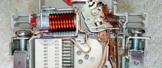
Connecting a single-phase meter does not require deep knowledge of electrical engineering as it has a simple connection diagram. All single-phase meters, both electronic and induction, have only four terminals for connection:
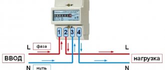
Contact 1 - for connecting the phase supply wire; Contact 2 - for connecting the phase wire going to the electrical receivers; Contact 3 - for connecting the neutral supply wire; Contact 4 - for connecting the neutral wire going to the electrical receivers. Thus, the input power cable is connected 1 and 3 2 and 4 . That is, connecting the wires to the meter looks like this:
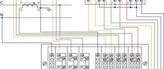
Taking into account all the requirements stated above, the connection diagram for a single-phase electricity meter should have the following form (since the connection diagram for an induction electric meter is identical to an electronic one, we present one general diagram with an electronic meter):
- Two-pole circuit breaker - for the ability to remove voltage from the meter for its safe replacement
- Single-pole circuit breakers - to protect the electrical network from short circuits and overloads
- RCD - for protection against electric shock and fire.
Three-phase meter connection diagram
Three-phase meters are used to meter electricity, as a rule, at facilities with a connected power of more than 12 kW (more than 60 Amperes), as well as in the presence of three-phase electrical equipment, regardless of power.
Connecting a three-phase meter is similar to a single-phase one, the only difference is in the number of connected phases. Three-phase meters have 8 terminals for connection:
Contact 1 - phase 1 input from input; Contact 2 - output of phase 1 to the load; Contact 3 - phase 2 input from input; Contact 4 - output of phase 2 to the load; Contact 5 - phase 3 input from input; Contact 6 - output of phase 3 to the load; Pin 7 - zero input from input; Contact 8 - zero output to the load.
Thus, connecting the wires to a three-phase meter will look like this:
However, it should be noted here that connecting the old meter has some features, namely, three-phase five-amp induction meters, which were previously used as direct-connection meters, have not 8 terminals for connection, but 11 for the possibility of connecting them through measuring transformers:
Direct connection of such a meter to the circuit is carried out as follows:
Contact 1 - phase 1 input from input; Pin 2 - jumper from pin 1; Contact 3 - output of phase 1 to the load; Contact 4 - phase 2 input from input; Pin 5 - jumper from pin 4; Contact 6 - phase 2 output to load; Contact 7 - phase 3 input from input; Pin 8 - jumper from pin 7; Contact 9 - phase 3 output to load; Pin 10 - zero input from input; Contact 11 - zero output to the load.
Since such meters are still found, we also present their connection diagram:
Taking into account all the above requirements, the connection diagram for a three-phase meter will look like this:
- Three-pole circuit breaker - for the ability to remove voltage from the meter for its safe replacement
- Three-pole circuit breaker - to protect three-phase electrical equipment from short circuits and overloads
- Single-pole circuit breakers - to protect single-phase electrical equipment from short circuits and overloads
- RCD - for protection against electric shock and fire.
Was this article useful to you? Or maybe you still have questions ? Write in the comments!
Didn’t find an article on the website on a topic that interests you regarding electrical engineering? Write to us here. We will definitely answer you.
When starting the installation of electrical wiring in a residential building or apartment, you need to understand that in any case you cannot do without installing an energy meter, that is, an electric meter. After all, the electricity metering scheme implies the presence of this device. In fact, it is the “heart” of the entire energy supply of the room. And many people think that only a professional electrician can do such work. In this article we will try to dispel this myth and figure out how difficult it is to connect such a device.
Read also: Cyclone water filter
It makes sense to reveal a little secret. Not everyone knows that the law allows the installation and replacement of an electric meter by the resident himself. Then you contact the organization that services the electrical networks and show that it is turned on correctly to check the functionality of the meter, as well as its sealing. At the same time, money will be saved that would have to be paid for the work of an electrician to install an electricity meter. But how to properly connect a single-phase electricity meter needs to be figured out step by step. After all, the operation of the entire network of the premises or apartment depends on this.
So, what is required to connect an electricity meter, how such a connection is made and how difficult it will be to install an electricity meter with your own hands - we will figure it out.
Types of meters
Before connecting a single-phase meter, you should select a suitable electricity meter. The same applies to a three-phase electric meter. The apartments use a single-phase electricity meter, which operates with a voltage of 220 volts. If you look at the contact terminals of such devices, you can see that the connection circuit of a single-phase meter contains 4 of them - these are the input and output of the phase wire, and the input-output of the zero wire.
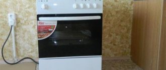
In a three-phase meter there are 8 such outputs - 3 pairs per “phase” and a pair for zero. The fact is that three-phase meters are used for a voltage of 380 volts and are connected if there is a need to power machine tools and similar equipment. Sometimes (much less often), to connect powerful electric stoves. There is no two-phase connection system.
Each of these types of metering devices can also be divided into single-tariff and two-tariff, in which only the circuit of the meter itself differs, but not the order of inclusion. The fact is that, according to current legislation, the cost of electricity spent in the period from 11 pm to 8 am is significantly lower than the “daytime” price, and therefore for those who spend the bulk of electricity at night, a two-tariff meter will be an excellent solution to save on utilities. A single-tariff meter does not have a time switching function, and therefore the cost of electricity does not change around the clock.
The connection diagram for a single-phase meter is no different for single-tariff and two-tariff devices, as is the connection diagram for three-phase meters; they are mounted in exactly the same way.
Also, these devices can be electronic and analog.
Tables for selecting cable cross-section by power
Conductor cross-section mm2 For cable with copper conductors Voltage 220 V Voltage 380 W Current A Power kW Current A Power kW
| 1,5 | 19 | 4,1 | 16 | 10,5 |
| 2,5 | 27 | 5,9 | 25 | 16,5 |
| 4 | 38 | 8,3 | 30 | 19,8 |
| 6 | 46 | 10,1 | 40 | 26,4 |
| 10 | 70 | 15,4 | 50 | 33,0 |
| 16 | 85 | 18,7 | 75 | 49,5 |
| 25 | 115 | 25,3 | 90 | 59,4 |
| 35 | 135 | 29,7 | 115 | 75,9 |
| 50 | 175 | 38,5 | 145 | 95,7 |
| 70 | 215 | 47,3 | 180 | 118,8 |
| 95 | 260 | 57,2 | 220 | 145,2 |
| 120 | 300 | 66 | 260 | 171,6 |
Conductor cross-section mm2 For cable with aluminum conductors Voltage 220 V Voltage 380 W Current A Power kW Current A Power kW
| 2,5 | 20 | 4,4 | 19 | 12,5 |
| 4 | 28 | 6,1 | 23 | 15,1 |
| 6 | 36 | 7,9 | 30 | 19,8 |
| 10 | 50 | 11 | 39 | 25,7 |
| 16 | 60 | 13,2 | 55 | 36,3 |
| 25 | 85 | 18,7 | 70 | 46,2 |
| 35 | 100 | 22 | 85 | 56,1 |
| 50 | 135 | 29,7 | 110 | 72,6 |
| 70 | 165 | 36,3 | 140 | 92,4 |
| 95 | 200 | 44,0 | 170 | 112,2 |
| 120 | 230 | 50,6 | 200 | 132,0 |
You can select and buy cables and wires in the cable and wire products section.
Preparation for installation
Before connecting the meter, if, of course, the electrical wiring of the room is installed from scratch, it is necessary in a place convenient for maintenance, preferably next to the power input, to install an input cabinet or box in which the circuit breakers and a single-phase electric meter will be secured. They can be either metal or plastic. It is important to know that according to the rules, electrical boxes are mounted no lower than 0.8 and no higher than 1.7 meters from the floor. This is done for ease of maintenance and readings, as well as for electrical safety.
Inside such cabinets, which are produced nowadays, DIN rails are already equipped, providing fastening of devices included in the circuit and grounding buses, and therefore modern installation is significantly simplified.
An input circuit breaker is installed on the DIN rail, usually more powerful than the distribution circuit, which will turn off one or another power line of the apartment, depending on the need, as well as the electric meter itself.
The main rule when installing such power panels is that all connections from the apartment or room are made first, and only lastly the load is supplied.
The tools to connect the electricity meter will require a hammer drill and mounting hardware for the box, pliers, flat-head and Phillips screwdrivers, and a knife for stripping the insulation.
Currently, I have chosen electrical panels and devices from ABB.
But knowledge of modular and panel products from Schneider Electric, Legrand, Hager allows me to assemble electrical panels from components from any manufacturer. Therefore, when choosing a company, I always go to meet the customer of the shield.
But it should be noted that the prices from these manufacturers are almost the same. The only difference is different series of devices, but even if they are similar in parameters, they are also the same.
Below I will give a comparative calculation of the cost of an electrical panel of different series of ABB and Schneider Electric for one of the orders (the calculation is already outdated, but is still relevant).
Comparison of prices for automatic machines, RCDs, switches from ABB and Schneider Electric.
Electrical panels, at the request of the customer, can be equipped with various additional “wants” and protections: light indicators, digital voltmeters, contactors with on/off switching of all or part of the load, timers (time relays) for turning on the load according to a schedule, voltage control relays, etc.
Installation
Having secured the power cabinet at the required level, you need to insert wiring from the apartment or room into it (the wires must enter from above). This is usually done either covertly or openly. In the second case, it is necessary to use corrugated plastic or metal armor.
Distribution machines are connected to each other from above with small pieces of wire. From the input circuit breaker (usually a two-pole device), one phase wire is connected to the 1st contact of the electric meter, and a jumper connects the second terminal to the distribution machine (how to connect the machine, as well as how to connect the meter, can be seen from the attached diagrams). Considering that all distribution circuit breakers are interconnected, the power to them will be the same. Wires that go inside the apartment or room are connected to them from below.
The circuit diagram for connecting a single-phase meter in a private house or apartment is not complicated, if, of course, it is fully understood.
The neutral wire from the input circuit breaker goes either directly to the second contact of the electric meter, or to it, but through a residual current device (RCD). It must be remembered that if, when connecting an RCD, the zero is connected to ground, then the residual current device will “knock out” and it will not work normally.
The jumper from the third contact of the electricity meter is connected to the zero bus, to which all neutral wires coming from the apartment or room are connected.
Here, in fact, is the entire connection of an electricity meter in general terms. After this, all that remains is to apply the phase to the input machine. In general, connecting an electric meter, the circuit of which is known, will not be difficult.
There is a small nuance in such work - the wires from the input machine to the single-phase or three-phase meter and from the meter to the distribution circuit breakers must have a larger cross-section than those coming from the apartment or room, and no less than the incoming power cable.
Read also: Adapter for grinder for grinding pipes
Features of some models of electricity meters
According to the above information, the contact terminals that provide connection to a single-phase electric meter are located as follows:
- phase wire input;
- outgoing phase wire;
- neutral wire input;
- outgoing neutral wire.
But for some devices, the connection diagram for the electric meter is slightly different. In them, the “phase” pair is located on the second two contacts, and the “zero” pair on the first (this applies mainly to old-style devices). Finding out the connection diagram for a particular electric meter is quite simple. Before connecting, you still have to remove the protective contact cover, and it is on its inner side that the location of the connected wires is shown. An electric meter whose connection diagram is reversed is not separately marked in any way, and therefore you can only find out about it from the information on the inside of the contact cover. Some may ask, what happens if I connect the meter incorrectly?
Modern devices have an LED, which, provided that the connection of the single-phase electricity meter is correct, will glow evenly without load, and when consumers are turned on, it will begin to blink at a certain interval. If the LED does not light up, this means that the phase and zero pairs are reversed. If it lights up, but does not blink under load, this indicates a reverse connection of the phase or zero pair, that is, connection of the input to the output. In any case, incorrect connection of the electric meter is unacceptable. The consequences of incorrectly connecting 1 wire to the meter can lead to its complete failure due to a short circuit. And what will happen if it happens, there is probably no need to explain.
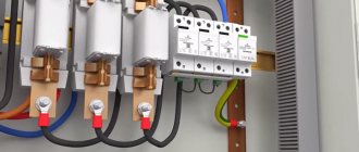
General principles for wiring in the panel
The switchboard contains all the equipment and mechanisms for connecting consumers to electricity
For its proper operation and safety, it is important to use suitable wires and high-quality parts, because due to a malfunction, users may be left without light, or a fire may even start. The function of conductors in an electrical panel is to connect controllers, indicators and other devices
The entire panel, including the metal casing, must be reliably grounded. Ideally, you should also put a lock on it so that unauthorized people do not have access to the equipment.
The connection must be made in such a way that the connecting wires do not sag. To do this, you need to carefully measure the distance between the connection elements and cut off a few centimeters more so that they can be inserted into the terminals. You cannot save on this, and if the calculations turn out to be incorrect, it is better to repeat the operation.
About ease of installation and maintenance
To simplify the installation and subsequent maintenance of the electrical box in general and the metering device in particular, wiring with different colors should be used. It must be remembered that with single-color wires, it is generally accepted that the neutral wire is blue and the phase wire is brown. With two-color ones, red-white is phase, and blue-white is zero. The yellow-green wire is always ground. But these are the primary colors. In general, the color of the phase wire can be any color except blue and yellow-green.
Compliance with the colors of the cable cores is also necessary for service companies. After all, a professional electrician will also pay attention to this when working, and will be guided primarily visually. Therefore, you should not neglect this rule.
Connecting a three-phase meter
Having understood the connection of a single-phase meter, you can move on to a three-phase one. Despite the fact that they have twice as many contact terminals, the essence of how to properly connect an electric meter to a 380-volt network does not change. The only difference in the circuit for such electricity metering devices is the presence of three pairs of phase connections. The last two contacts also go to the input and output of the neutral wire.
The only thing that can be a little more difficult in connecting three-phase electricity meters is if the meter is a secondary switching device. In this case, power to the electric meter is supplied from transformers that are installed on the input power busbars. Otherwise, the installation of such metering devices does not differ from the connection of direct connection devices, which are currently the most common.
It is important that when carrying out electrical installation of the wiring of an electrical cabinet or box, it is always possible to turn off the input voltage, since regardless of the rating, whether it is 220 volts or 380, it is life-threatening, and therefore any work in this direction must be carried out with the power turned off.
Methods for installing wiring in an apartment
It is important to immediately make a reservation that the following options will only be relevant for buildings with walls made of concrete or brick. They are not suitable for wooden houses, so the methods are not universal
The first method will be relevant for those houses where there is not even a layer of plaster on the walls. Then the wiring can be placed directly on the surface of the walls. There are also two methods here, which were already mentioned earlier:
- Place the cables in corrugated plastic pipes if the thickness of the finish allows.
- Simply lay the cables open if they have double or triple insulation.
The second method is encountered most often, because it is suitable for cases when:
- The plaster has already been applied.
- Its layer will not cover the wires and you will have to make grooves directly in the wall.
This is a more difficult and longer path, but most often it turns out to be the only suitable one. In addition to the fact that the grooves have to be made, the wires in them will also need to be carefully fixed - with plaster patches or plastic staples.
*(Dowel staples are especially suitable for ceiling wiring)
To make all the grooves correctly, it is better to make markings according to the diagram directly on the wall, then there will definitely not be any difficulties and there will be a chance to check everything again and correct something.
Now you need to determine how to lay the cables themselves. The lines from the distribution board to each junction box can be laid using the methods described in this table.
| Highway location | Peculiarities |
| Along the upper edge of the wall in a groove or corrugated pipe | Most often used |
| Over the floors until the floor screeds are poured (in plastic pipes) | This is the shortest way. Here, by the way, grooves are not useful either, since when the floor is filled, all the wires will be hidden. For such wiring, sockets built into baseboards are usually needed. By the way, now you can purchase special kits - a special plinth with cable channels, sockets, switches, junction boxes, etc. True, it is not suitable for any finish. |
| Along the ceiling | Here, most likely, you will have to make grooves, however, the consumption of materials will also be economical. Junction boxes can also be placed on the ceiling, but this will hardly be convenient when repairs are required. This method is only relevant when a suspended or suspended ceiling is intended to hide the lines. |
When installing the wiring yourself, only the first option is suitable, and despite the great advantages of the other two, it is no worse than them. It will just require more time, but since the plan to install the wiring with your own hands has reached the strobing stage, the hardest part is already over.
*(Grooves are the penultimate stage on the route of wiring)
Pulling contacts
Surely, if a person installed electrical wiring in an apartment on his own, he already knows that the connection contacts must be tight enough to prevent heating and failure of the wires. But it won’t hurt to remind you of this. Moreover, this rule applies primarily to the electric meter and power cabinet circuit breakers.
The contact terminals of the electricity meter have two mounting screws. First, the wire is fixed in the socket with the upper screw, then the lower one is pulled through. It is important to remember that after the power cabinet has been operating under load for one to two weeks, it is necessary to re-check the tightness of the fixing screws of the electric meter and machines. Particular attention should be paid to the zero bus and its contacts, since if the tightening is insufficient, it is the “zero” that begins to “burn.”
Some tips and safety measures
To summarize all of the above, it makes sense to summarize the basic safety measures when installing power cabinets and connecting electric meters:
- All work is carried out with the voltage removed;
- The wiring should start from the apartment or room, and the power input should be connected last;
If you clearly understand how to connect a single-phase or three-phase electric meter, no special difficulties will arise during its installation, and therefore it is quite possible to connect the electric meter yourself. And if all of the above measures are observed, the electrical wiring will continue to bring light into the apartment for a long time, and its maintenance will not cause any problems.
Commissioning or reconstruction of electrical wiring in a house or apartment is rarely complete without installing or replacing an electric meter. According to the standards, work can only be performed by specially trained people who have permission to work in networks with voltages up to 1000 V. But you can install all the elements and connect the meter to the load (electrical appliances) without connecting the power supply yourself. Afterwards, you need to call a representative of the energy supply organization to test, seal and start up the system.
One of the housing options for the meter
Input wire
An example of connecting an input to a private house
- Although this does not directly concern the calculation of electrical wiring, still complete this step. Check the cross-section (or the sum of cross-sections, if you have several lines) of the wires after input with the cross-section of the input conductor.
- The input must either be made with a wire of a larger cross-section or be equal. If the opposite happens, then you need to reduce your appetite (the power of the appliances installed in the house), or contact the electricity supplier company.
- A situation may occur when correctly calculated internal wiring will withstand but the input will burn out. Therefore, it is necessary to increase its diameter and permissible current. This can be done by a service serving external networks.
Usually this is a paid procedure and at the same time it is necessary to renew the contract due to an increase in the limit of supplied energy.
Correct calculation of wiring will help to avoid frequent repairs.
I hope our article has fully covered the topic for you: calculating electrical wiring in a house. Even if you do not carry out this work yourself, knowing the principles will help you save money when ordering materials or services. May your home always be illuminated, comfortable and safe.
Connecting a meter: rules and basic requirements
Exactly all the requirements are specified in the PUE, and the basic rules are as follows:
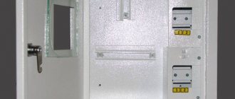
- Must be installed with protection from weather conditions. Traditionally they are mounted in special boxes (boxes) made of non-flammable plastic. For outdoor installation, the boxes must be sealed and must provide the ability to control readings (have glass opposite the display).
- Fixed at a height of 0.8-1.7 m.
- The meter is connected using copper wires with a cross-section corresponding to the maximum current load (available in the technical specifications). The minimum cross-section for connecting an apartment electric meter is 2.5 mm 2 (for a single-phase network this is a current of 25 A, which is very low today).
- The conductors are insulated, without twists or branches.
- With a single-phase network, the state verification date of the meter is no older than 2 years, with a three-phase network - one year.
Read also: Typical power supply faults
The installation location of the meter in apartment buildings is regulated by the project. The meter can be installed on the landing or in the apartment - in the panel. If placed in an apartment, it is usually not far from the door.
Input panel complete set
There are also several options in a private house. If the pole is in the yard, you can place the meter on the pole, but it’s better to place it indoors. If, according to the requirements of the energy supply organization, it must be located on the street, they place it on the front side of the house in a sealed box. The machines going to groups of consumers (various devices) are mounted in another box in the room. Also, one of the requirements when installing electrical wiring in a private house: the wires must be visually inspected.
Installing a meter on a pole
In order to be able to carry out work on the electric meter, an input switch or machine is installed in front of it. It is also sealed, but there is no way to put a seal on the device itself, like on a meter. It is necessary to provide for the possibility of separate sealing of this device - buy a small box and mount it inside the apartment panel or place it separately on the landing. When connecting a meter in a private house, the options are the same: in the same box with the meter on the street (the entire box is sealed), in a separate box next to it.
Connection diagram for a single-phase electric meter
Meters for a 220 V network can be mechanical or electronic. They are also divided into single-tariff and two-tariff. Let us say right away that connecting any type of meter, including two-tariff ones, is carried out according to the same scheme. The whole difference is in the “filling”, which is not available to the consumer.
If you get to the terminal plate of any single-phase meter, you will see four contacts. The connection diagram is indicated on the back of the terminal block cover, and in a graphical representation everything looks like in the photo below.
How to connect a single-phase meter
If you decipher the diagram, you get the following connection order:
- Phase wires are connected to terminals 1 and 2. The phase of the input cable comes to the 1st terminal, the phase to the consumers goes from the second. During installation, the load phase is connected first, and after it is secured, the input phase is connected.
- The neutral wire is connected to terminals 3 and 4 using the same principle. To the 3rd contact there is a neutral from the input, to the fourth - from consumers (machines). The order of connecting the contacts is similar - first 4, then 3.
The meter is connected with wires stripped to 1.7-2 cm. The specific figure is indicated in the accompanying document. If the wire is stranded, lugs are installed at its ends, which are selected according to thickness and rated current. They are crimped with pliers (can be clamped with pliers).
When connecting, the bare conductor is inserted all the way into the socket, which is located under the contact pad. In this case, it is necessary to ensure that no insulation gets under the clamp, and also that the cleaned wire does not stick out from the housing. That is, the length of the stripped conductor must be maintained exactly.
The wire is fixed in old models with one screw, in new ones - with two. If there are two mounting screws, tighten the one on the far side first. Tug the wire slightly to make sure it is secure, then tighten the second screw. After 10-15 minutes the contact is tightened: copper is a soft metal and is pressed down a little.
Read how to do the wiring in your home yourself here. The features of electrical wiring in a wooden house are written here.
This applies to connecting wires to a single-phase meter. Now about the connection diagram. As already mentioned, an input machine is placed in front of the electric meter. Its rating is equal to the maximum load current; it is triggered when it is exceeded, excluding equipment damage. Afterwards they install an RCD, which is triggered when the insulation breaks down or if someone touches live wires. The diagram is shown in the photo below.
Connection diagram for a single-phase electricity meter
The circuit is not difficult to understand: from the input, zero and phase go to the input of the circuit breaker. From its output they go to the meter, and from the corresponding output terminals (2 and 4) they go to the RCD, from the output of which the phase is supplied to the load breakers, and the zero (neutral) goes to the zero bus.
Please note that the input circuit breaker and the input RCD are two-contact (two wires enter) so that both circuits open - phase and zero (neutral). If you look at the diagram, you will see that the load breakers are single-pole (only one wire goes to them), and the neutral is supplied directly from the bus.
Watch the meter connection in video format. The model is mechanical, but the process of connecting the wires is no different.
What are the dangers of exceeding the permitted power?
Example of a consumer notification
Based on Russian Government Decree No. 624, if the maximum load is exceeded, the electric company has the right to limit the consumer’s access to the power grid. The reason is non-compliance with obligations under the electricity supply contract.
In case of accidents or during work on the power line, Energosbyt employees take measurements. In cases where inaccuracies are identified, they send notifications. The user must take measures to eliminate excess power within 10 days. The degree of his responsibility is determined by the violation:
- ignoring the notification after 10 days – turning off the power supply to the facility;
- connection bypassing the line - charging a fine, recalculating the power according to the maximum indicator from the moment of inspection, connecting to the public network at the expense of the violator;
- non-contractual use – fine for lack of agreement, recalculation based on normal power indicator.
The basis for termination of sanctions is documentary evidence of the adoption of measures. However, UOMPE, CCD and PZR devices are installed on the user line.
The act of non-registration is drawn up in the presence of 2 witnesses, with photos and video recording of the process.