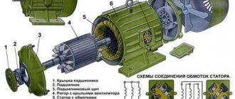
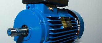
Operating principle of a single-phase asynchronous machine
The operation of an asynchronous motor is based on the interaction of the rotating magnetic field of the stator and the currents induced by it in the motor rotor. When the rotation frequency of the pulsating magnetic fields differs, a torque occurs. It is this principle that is followed when regulating the rotation speed of an asynchronous motor using a frequency converter.
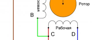
The electric motor can in fact be considered two-phase, but it has only one working stator winding, the second, located relative to the main one at an angle of 90°, is the starting one.
The starting winding occupies 1/3 of the slots in the stator structure, and the main winding accounts for 23 stator slots.
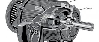
The rotor of a single-phase motor, short-circuited, placed in a stationary magnetic field of the stator, begins to rotate.
Fig. No. 1 Schematic drawing of a motor, demonstrating the principle of operation of a single-phase asynchronous motor.
Purpose and advantages
Electromagnetic forces generated under the influence of the magnetic field created by the armature winding set the rotor in motion. Its rotation occurs at a speed determined by the frequency of the mains current. At a frequency of 50 Hz, 50 oscillations occur within 1 s. Therefore, the rotor rotation speed will be 3000 rpm.
The purpose of frequency converters is to ensure effective motor control by changing current frequency parameters.
The advantages of these devices are:
- ensuring smooth operation of the motor at the time of starting and braking;
- regulation of the operation of engines assembled in a group;
- no need to use gearboxes and other mechanical devices to control engine speed;
- ensuring the operation of drive control systems on a multifunctional basis;
- possibility of adjustments in settings without interrupting the operation of the unit.
Tags: automatic, asynchronous, sconce, throw, vector, upper, view, choice, switch, generator, engine, house, , capacity, star, sign, like, kilowatt, computer, capacitor, contactor, circuit, , magnet, power , load, voltage, nominal, smooth, connection, rule, principle, wire, manufacturer, start, , work, regulator, relay, light, network, connection, means, term, circuit, ten, type, current, transformer, triangle, three-phase, , phase, shield, electric motor, power tool, effect
Rotation speed control of single-phase motors
There are several ways to regulate the rotation speed of a single-phase motor.
- Controlling motor slip or voltage variation. The method is relevant for units with a fan load; it is recommended to use motors with increased power. The disadvantage of this method is heating of the motor windings.
- Step control of engine rotation speed using an autotransformer.
Fig. No. 2. Adjustment circuit using an autotransformer.
The advantages of the circuit are that the output voltage has a pure sinusoid. The transformer's ability to withstand overloads has a large power reserve.
Disadvantages - the autotransformer has large overall dimensions.
Using a thyristor engine speed controller. Thyristor switches connected back-to-back are used.
Rice. No. 3. Scheme of thyristor control of a single-phase asynchronous electric motor.
When used to regulate the rotation speed of single-phase asynchronous motors, the circuit is modified to avoid the negative influence of the induction load. LRC circuits are added to protect the power switches, a capacitor is used to correct the voltage wave, the minimum engine power is limited, this ensures that the engine starts. The thyristor must have a current higher than the motor current.
Transistor voltage regulator
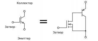
The circuit uses pulse-width modulation (PWM) using an output stage built using field-effect or bipolar IGBT transistors.
Rice. No. 4. Scheme of using PWM to regulate a single-phase asynchronous electric motor.
Frequency regulation of a single-phase asynchronous electric motor is considered the main way to regulate the motor frequency, power, utilization efficiency, speed and energy saving indicators.
Rice. No. 5. Electric motor control circuit without excluding the capacitor from the design.
What is a three-phase network?
Phase means a change in direction between the magnitudes of the electrical network at the same point in time. In the case of 3 f. current, use three voltages oriented in 3 different directions. Thus, the network voltage is calculated by adding vector quantities, and is not equal to the algebraic sum of all voltages.
Let's look at the example of the same engine. When applying 380 V to the coil, different phase pairs are used in a specific sequence for each winding. This is actually why the circuit is characterized by 380 Volts, and not by scalar addition (220 + 220 + 220 = 660)V. This explanation is very simplified and not entirely complete, but hopefully well presented. Yes, and it is written so that it is clear to us, electric “teapots”.
In technical terms, in a three-phase electrical network, circuits of conductors carry three variable values of physical quantities that reach instantaneous peaks at different times. Taking one conductor as a reference, the other two flows are delayed in time by one third and two thirds of one current cycle. This delay between phases has the effect of transferring power during each cycle and also allows the production of a rotating magnetic field.
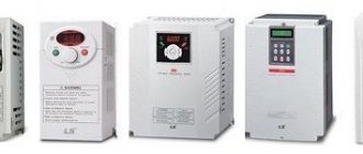
Frequency converter: types, principle of operation, connection diagrams
The frequency converter allows its owner to reduce energy consumption and automate processes in equipment and production management.
The main components of the frequency converter: rectifier, capacitor, IGBT transistors assembled into an output stage.
Thanks to the ability to control the parameters of the output frequency and voltage, a good energy-saving effect is achieved. Energy saving is expressed in the following:
- The engine maintains a constant current torque of the shaft. This is due to the interaction of the output frequency of the inverter converter with the engine speed and, accordingly, the dependence of voltage and torque on the engine shaft. This means that the converter makes it possible to automatically regulate the output voltage when it detects a voltage value that exceeds the norm with a certain operating frequency necessary to maintain the required torque. All inverter converters with vector control have the function of maintaining constant torque on the shaft.
- The frequency converter is used to regulate the operation of pumping units (see page). When receiving a signal from a pressure sensor, the frequency generator reduces the performance of the pumping unit. As the engine speed decreases, the output voltage consumption decreases. Thus, standard water consumption by a pump requires 50Hz industrial frequency and 400V voltage. Using the power formula, you can calculate the ratio of power consumption.
By reducing the frequency to 40Hz, the voltage is reduced to 250V, which means that the number of pump revolutions is reduced and energy consumption is reduced by 2.56 times.
Rice. No. 6. Using a Speedrive frequency converter to regulate pumping units using the CKEA MULTI 35 system.
To increase the energy efficiency of using a frequency converter in electric motor control, you must do the following:
- The frequency converter must match the parameters of the electric motor.
- The frequency generator is selected in accordance with the type of working equipment for which it is intended. Thus, the frequency converter for pumps operates in accordance with the parameters included in the program to control the operation of the pump.
- Precise settings of control parameters in manual and automatic mode.
- The frequency converter allows the use of energy saving mode.
- Vector control mode allows automatic adjustment of engine control.
Additional features and options
A modern frequency converter for an electric motor is a complex device. If it is processor-based, then it has many functions. Even inexpensive models can have wide functionality. To make a justified choice, you should know what each of the parameters means and why this or that function is needed.
- Output frequency or range of its variation. Everything is clear here. This parameter describes the possibilities for changing the output frequency.
- Voltage regulation limits. There are no questions either.
- Frequency conversion type. Can be vector or scalar. Scalar is used in simpler models. The parameters are monitored by the relationship between voltage and frequency. The vector type of frequency conversion to FM adjusts the work so that, relative to the load, the torque is constant. This control method is more complex and reliable, and is used in more expensive models.
- Availability of PID controller. Maintains pressure, temperature and speed within specified limits (set using a knob or programmed). To communicate with other controls, it must have signal outputs (analog and/or digital).
- Speed adjustment. Helps stabilize engine operation during power changes or surges.
- Type of braking. It is usually recommended to stop the motor on a free run - turn off the power and wait until it stops. Smooth braking can be used - a gradual decrease in voltage. Mechanical braking - when the speed of rotation of the shaft is slowed down due to friction. The rotor stops fastest during dynamic braking. In this case, a constant voltage is applied to one of the phases. It interacts with the rotor, stopping it in a short period of time.
- Number of outputs with different frequencies. Such a frequency converter for an electric motor can serve several engines at once with different (fixed) rotation speeds.
In addition to parameters and additional features, the performance is affected by the build quality. Naturally, it is better to take equipment from well-known manufacturers. ABB, Siemens, Mitsubishi, Omron have proven themselves well. But their frequencies cannot be called cheap
If you need to save money and appearance is not so important, pay attention to domestic and Belarusian manufacturers. The external design, as usual, wants to be better, but the performance and stability are not bad
Single-phase frequency converter
The compact frequency conversion device is used to control single-phase electric motors for household equipment. Most frequency converters have the following design capabilities:
- Most models use the latest vector control technologies in their design.
- They provide improved torque for single-phase motors.
- Energy saving is set to automatic mode.
- Some models of frequency converters use a removable control panel.
- Built-in PLC controller (it is indispensable for creating data collection and transmission devices, for creating telemetry systems, and integrates devices with various protocols and communication interfaces into a common network).
- Built-in PID controller (monitors and regulates temperature, pressure and technological processes).
- The output voltage is adjusted automatically.
Fig. No. 7. Modern Optidrive converter with basic functional features.
Important: A single-phase frequency converter, powered by a single-phase network with a voltage of 220V, produces three linear voltages, the value of each of them is 220V. That is, the linear voltage between the 2 phases is directly dependent on the output voltage of the frequency converter itself.
The frequency converter does not serve for double voltage conversion; due to the presence of a PWM regulator in the design, it can increase the voltage value by no more than 10%.
The main task of a single-phase frequency converter is to provide power to both single- and three-phase electric motors. In this case, the motor current will correspond to the connection parameters from a three-phase network and remain constant
How do converters work?
They are based on a double conversion inverter.
The operating principle is as follows:
- first, the sinusoidal input current 220 or 380V is rectified, passing through the diode bridge;
- after that, it goes to the capacitor group, where it is smoothed; having passed through the capacitors, it is supplied to control microcircuits and a bipolar BTI transistor, or rather bridge switches, where it is used to form a three-phase pulse-width sequence of the given parameters;
- the received pulses, having the shape of a rectangle, under the influence of the inductance of the windings are converted at the output into a sinusoidal voltage.
Below is a diagram to help you understand how a frequency converter works:
Frequency regulation of single-phase asynchronous electric motors
The first thing we pay attention to when choosing a frequency converter for our equipment is the correspondence of the mains voltage and the rated value of the load current for which the motor is designed. The connection method is selected relative to the operating current.
The main thing in the connection diagram is the presence of a phase-shifting capacitor; it serves to shift the voltage supplied to the starting winding. It is used to start the engine, sometimes after the engine has started, the starting winding along with the capacitor is turned off, sometimes it remains on.
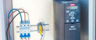
Connection features
As mentioned above, not every frequency converter can work with a single-phase motor, since when it is connected, the third (unconnected) phase will actually be open, which will cause an error. Therefore, it is necessary to carefully read the documentation for the inverter - the manufacturer must clearly indicate that it is possible to connect and operate a single-phase load.
Since a single-phase motor contains a capacitor, when changing the operating frequency it will not be possible to provide the required phase shift, and the motor will overheat at lower frequencies (less than 30 Hz). This should be taken into account when choosing the operating frequency range and the drive cooling method.
When a single-phase motor is connected, operational reverse via the control panel or inverter settings is not possible. You can change the direction of rotation by changing the wiring diagram of the windings inside the motor.