Every experienced electrical engineer knows that the distribution of current density in a conductor is nonlinear. The closer to the central axis, the smaller the signal amplitude. At high frequencies, for a correct calculation it is enough to take into account the passage of waves through a certain surface layer. This phenomenon, the skin effect, can perform useful functions. For successful application in practice, in addition to the general theory, you need to study the calculation methodology.
Economical pipeline heating systems are created based on the skin effect.
Explanation of the surface effect
It should be emphasized that the current density is the same when connecting the conductor to a constant voltage power source. However, the situation changes when a wave signal passes through.
Current density distribution in a conductor
Physical picture of occurrence
To explain the reasons for the phenomenon, you can use the second part of the explanatory picture above. The force effects that are generated by an alternating field are shown in graphical form. The electrical component (E) is directed opposite to the current (I), which explains the resulting resistance and the corresponding decrease in amplitude. As you approach the surface, the opposite effect will appear. It is caused by the coincidence of tension vectors.
Equation describing the skin effect
To express the amplitude in terms of current density, constitutive relations are taken from the classical equations of Ohm's law and Maxwell's formulas. Using the differential over a given time interval, you can calculate the values of the magnetic and electric components of the field. In a simplified form, we consider an infinite conducting sample created from a homogeneous material.
Current source
The water in the hose comes from a water supply, a spring with water in the ground - in general, not from nowhere. Electric current also has its own source.
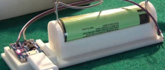
The source can be, for example, a galvanic cell (a conventional battery). A battery works based on chemical reactions inside it. These reactions release energy, which is then transferred to the electrical circuit.
Any source necessarily has poles - “plus” and “minus”. The poles are its extreme positions. Essentially the terminals to which an electrical circuit is connected. Actually, the current flows from “+” to “-”.
Formula for determining the cutoff frequency of the conductor diameter
Hall effect
For practical calculations, individual minor factors are neglected. For example, to determine the cutoff frequency (Fcp), the circuit of a radio device is calculated based on the diameter (D) of the corresponding conductor. The most important characteristic of a certain material is added to the formula - resistivity (Rу) or conductivity (Sу). The dependence of the marked parameters shows the following expression:
Fav = 4/ (π*μ*Sу*D2),
where μ is a constant value (μ = 4* Su*10-7 Henry per meter).
Skin layer thickness
Capacitor in AC circuit
From the definition discussed in the previous section, the inverse dependence of the current density on the signal frequency is clear. The following table clearly demonstrates the “active” layer of a copper conductor. When the energy flow decreases multiple times in depth at a certain level, the use of thick power lines is inappropriate.
| Parameter | Values | ||||
| Signal frequency, Hz | 50 | 60 | 10 000 | 100 000 | 1 000 000 |
| Skin layer thickness, mm | 9,34 | 8,53 | 0,66 | 0,21 | 0,067 |
The first two columns show values for standard AC power. This data demonstrates that a relatively small change in frequency (10 Hz) renders 1.62 mm diameter conductor (copper) useless. It is not difficult to calculate significant savings when creating a long line after appropriate optimization of signal parameters. It should be remembered that each metal differs in the depth of the effective layer. Which option to choose will become clear after a thorough study of the intended purpose of the design.
Current direction
Previously, in physics textbooks they wrote this: once upon a time they decided that the current was directed from plus to minus, and then they found out that electrons flow through the wires. But these electrons are negative, which means they cannot go to minus. But since we’ve already agreed on the direction, let’s leave it as it is. The question then arose for everyone: why can’t the direction of the current be changed? But no one received an answer.
Now they write it a little differently: positive particles flow along the conductor from plus to minus, and the current is directed there. No one has any questions here.
So which version is correct?
Actually, both. The charge carriers in each type of material are different. In metals these are electrons, in electrolytes they are ions. Each type of particle has its own signs and need to run to the oppositely charged pole of the current source.
We will not choose the direction of current for each type of material in order to solve the problem! Therefore, it is customary to direct the current from plus to minus. In most school course problems, the direction of the current does not play a role, but there is that insidious minority where this point will be very important. Therefore, remember - we direct the current from plus to minus .
Anomalous skin effect
A careful study of the phenomenon allows us to draw several important conclusions. As shown in specific examples, the skin layer has a shallow depth. However, the corresponding distance is much less than the average free path of charged particles. It should not be forgotten that a certain amount of energy must be spent on the corresponding movement. Overcoming the electrical resistance of the material is accompanied by heating.
If you lower the temperature, the conductivity will increase. At the same time, the free path will increase, and the thickness of the considered part of the conductor will decrease. At a certain level, the standard mechanism of wave interactions will become insignificant. The anomalous skin effect is a change in the size of the layer in which the current density is sufficiently high for practical use.
Subscribe to the newsletter
The existence of the modern world cannot be imagined without electric current. It ensures the functioning of a huge variety of devices and electrical appliances, as well as entire systems. The concept of “electric current” helps to draw an analogy between this phenomenon and the flow of liquid, which gives this term some clarity. Electric current flows due to the fact that the electromagnetic field moves along a conducting medium at a speed approximately equal to the speed of light. This movement goes in the direction from greater potential to less, that is, from “+” to “-”. At the same time, charge carriers move slightly slower and in different directions (depending on the material).
What are the types of charge carriers?
There are two types of charge carriers - negative and positive. Ions and electrons can have a charge with a minus sign, but generally only ions have a positive charge. Negative charges move in the direction of greater potential, and positive charges move in the opposite direction. This movement leads to the appearance of electric current. This uncertainty is eliminated in the generally accepted rule, which states that current always flows from “+” to “-”, regardless of the type of charges.
How do charges move in metals?
Almost all metals used in electrical engineering do not contain ions because they are in a solid state. They are characterized by electronic type conductivity. This means that free electrons, acting as charge carriers, move in the direction opposite to the current.
Metals have relatively low electrical resistance. If there is no potential difference, the electric field strips electrons from their orbits. For this reason, at a small potential difference, a significant number of charge carriers appears.
How do charges move in semiconductors?
Semiconductors have much lower conductivity than metals (at room temperature). There are two types of semiconductors - n and p. Semiconductors of the first type contain an excess of electrons. When they go to p-type, they become deficient. The remaining electrons move without much difficulty to their possible places inside the atom. This is equivalent to the movement of charges with a “+” sign. Since electrons in semiconductors are weakly bound to atoms, as the temperature increases, the number of unbound electrons changes and the conductivity of the semiconductor increases rapidly. Conclusion: in semiconductors, charges can move in the direction of current flow or in the opposite direction (p- and n-type, respectively).
How do charges move in gases and liquids?
In liquids and gases, charge carriers are ions, which can be negative (so-called cations) and positive (anions). If the number of cations is greater, they move in the opposite direction of the current. If anions predominate, their movement coincides with the direction of the current.
Source
Application
The surface effect allows for local heating of part of the conductor when alternating current is passed through. This principle is used to heat the pipeline in winter. Correct application of technology implies the following advantages:
- lack of accompanying control and functional devices;
- virtually unlimited route length;
- possibility of safe use of high temperatures.
Frequency distribution of current density is used to transmit information signals along power lines. If the wavelength is sufficiently reduced, the proximity of the central part of the conductor will not be an obstacle. The modulated microwave component passes through the surface layer. To create data packets and decrypt, special encoding (decoding) devices are used.
For your information. Similar mechanisms are used in the oil industry to assess well productivity. The skin factor determines the resistance to fluid movement in the formation area close to the technological hole. This parameter is used to estimate the actual production volume compared to ideal conditions.
The influence of cables on the parameters of amplifier-speaker and microphone-mixer systems
The vast majority of audiophiles are confident in the significant influence of cables on sound. Many articles have been written on this topic, both supporters and opponents of this theory, however, I have not come across a single article containing real technical calculations that would prove this or that point of view. The texts usually contain their own conjectures, which are sometimes far from reality. I used technical knowledge and calculations to understand this topic. Most often, in addition to the active resistance of the conductor, audiophiles mention three factors that supposedly influence the final parameters of the electrical circuit:
- capacitance (since the cable consists of a pair of conductors);
- inductive reactance;
- skin effect.
Let's consider the first two factors together, since they have a very close relationship.
The fact is that there is an equivalent circuit of an infinitesimal segment of a long power line, which is a four-terminal network containing linear resistance, capacitance, inductance and conductivity (Figure 1). Thus, any long line is a collection of data quadripoles connected in series. Figure 1 - Equivalent diagram of an infinitely small segment of a long line However, here it should be taken into account that we are talking specifically about a long line. By definition, a long line is a regular power transmission line, the length of which is many times greater than the wavelength of the oscillations propagating in it, and the distance between the conductors and the transverse size of the conductors are many times less than the wavelength, i.e. the following relations hold: where λ
– wavelength,
L
– line length,
a
– conductor cross-section,
b
– distance between conductors.
For the upper limit frequency ν = 20000
Hz of the audible range, the wavelength
λ = c⁄ν
, where
c
is the speed of light, will be equal to 300000000/20000=15000 m, or 15 km. For a frequency of 50 Hz, the wavelength will reach six thousand kilometers. Naturally, such lengths of speaker cables are not used, and therefore the long line model is clearly not suitable for them. For lines whose length is much smaller or comparable to the oscillation wavelength, there is an equivalent short line circuit (Figure 2).
Figure 2 - Equivalent circuit of an infinitesimal segment of a short line
As can be seen from the figure, the conductivity and inductance of the line are no longer taken into account here, since their values are negligible (for a short line). This means that there is no point in considering the second factor. All that remains is the container. Let us now calculate the input and output resistance of our passive quadrupole and look at its transfer characteristic. The input resistance for the first circuit will be equal to: The output resistance for the second circuit: Voltage transfer characteristic: Transfer characteristic modulus: Now let’s take one meter of some real cable for calculation. I went to the website audiomania.ru and found a cheap Onetech Rapid Two INT0107 microphone cable. One conductor of such a cable has a cross-section of 0.21 sq. mm, which approximately corresponds to AWG 24 caliber, according to the American standard. From the book Fundamentals of Telecommunications, we will use a table that shows linear resistances and capacitances (Figure 3).
Figure 3 – Table of cable parameters (for 1 kHz)
For AWG 24 C=40
nF⁄km
=40
pF⁄m;
R=170
Ohm⁄km
=0.17
Ohm⁄m,
ν=1000
Hz.
Let's substitute these values into formula (4): I deliberately left more than 15 decimal places to show how tiny the change in voltage is when passing through a four-terminal network. By the way, it is difficult to even find a device that will show such accuracy. Let's now look at the limit value of the frequency spectrum perceived by the human ear ( ν_н=20
Hz,
ν_в=20000
Hz):
Skeptics will say: “This is a calculation for just one meter of cable.” Well, let's see what happens to the voltage transfer characteristic module for, say, five meters of cable (for 1 kHz). Changes for five meters of cable are still negligible to be taken into account.
About the skin effect
By definition, the skin effect (or surface effect) is the effect of a decrease in the amplitude of electromagnetic waves as they penetrate deep into a conducting medium. As a result of this effect, for example, high-frequency alternating current when flowing through a conductor is not distributed evenly over the cross-section, but mainly in the surface layer. It is due to the uneven distribution of current that the effective cross-section of the conductor decreases, and, consequently, the resistance increases. This idea of the skin effect forces audiophiles to buy silver-plated wires, which, naturally, are much more expensive than ordinary ones (using a thin layer of silver can actually combat the skin effect for high frequencies, due to the lower resistivity of silver). But does this make sense? The derivation of the formula describing the skin effect comes from Maxwell's equation. There is no point in describing it; all information can be found in textbooks for universities (for example, in Sivukhin’s textbook). Instead of a conclusion, we will use a simplified formula to calculate the thickness of the skin layer (the layer in the conductor where almost all the current is concentrated): where ρ
is the resistivity,
μ_m
is the relative magnetic permeability,
f
is the frequency.
For copper: ρ=0.018
(Ohm∙sq.mm)/m;
μ_m=0.999994
at frequency
f=20000
Hz: Let's calculate the cross-sectional area in which we have a skin effect: Thus, for any wire gauge that has a cross-sectional area less than 2.95 sq.mm, there is no skin effect at all influence.
About the damping ratio
Many lovers of good sound often refer to the damping coefficient (or damping factor), supposedly described in the German standard DIN 45500 and defining it as the ratio of the load resistance to the output impedance of the amplifier. It is believed that a system falls under the definition of Hi-Fi if its damping coefficient is more than 20. At the same time, the coefficient allegedly also takes into account the resistance of the cables (it is summed with the output impedance of the amplifier), and only its active part. If we use this coefficient, it turns out that the resistance of the conductors not only has a tremendous impact on the speaker, but is also almost one of the most important parameters of the speaker. For example, let's take the output impedance of the amplifier to be 0.01 Ohm, then, when connecting a 4 Ohm speaker with a AWG 24 caliber cable 1 meter long, we get: The damping coefficient has hardly exceeded 20, and this is only for one meter of cable! What's the matter and who to believe? To be honest, I have not read the DIN 45500 standard, since it is written in German, which I do not speak. However, in Russian national standards there are two analogues to this DIN 45500 for speakers and amplifiers - GOST 23262-88 and GOST 24388-88, respectively. In none of them is the “damping coefficient” ever mentioned, as in other GOSTs, references to which are present in them. This term also does not appear in Russian-language literature. There is information about this parameter in English-language resources, but it is rather scanty, without links to authoritative sources. Based on the research conducted at the beginning of the article, I am almost certain that the “damping factor” is nothing more than a myth created by marketers to increase sales of thick and silver-plated cables that cost hundreds and even thousands of dollars. They tried to adjust the voltage matching in acoustic systems to a certain parameter, but the damping coefficient does not characterize the speaker either quantitatively or qualitatively.
About impedance matching and “guitar” cables
Although the article initially discussed the impact specifically on the acoustic system, the topic of guitar combo amplifiers and cables for connecting electric guitars to them came up in the comments. It should be noted that this topic requires a slightly different approach to consideration. And that's why. Any “amplifier-speaker” or “microphone-mixing console” system requires voltage matching of resistance
: the load resistance must be much greater than the source output resistance (in other words, the internal resistance of the signal source). In this case, the voltage, which is the carrier of the signal, will pass from the source to the load with minimal losses. It is to this type of coordination that the article primarily relates.
With guitar combo amps the story is a little different. Here, due to the nature of the electric guitar pickup, power matching is used. In this case, the load resistance must be complexly coupled with the internal resistance of the source (or be close to this state).
With any type of matching for any signal source, the cable is a simple low-pass filter. The formula for determining the cutoff frequency is as follows: This can be considered an additional limitation that is imposed on the entire system as a whole. In the case of voltage matching, the cutoff frequency will be very high: much higher than the upper limit frequency of the audio spectrum. The output impedance of an electric guitar can reach hundreds of thousands of kOhms (I couldn’t find a more precise interval in the technical literature), here the cutoff frequency can be within the audio spectrum. Since the internal resistance of the source is very large, the cable resistance can be neglected for this formula, that is, the most important parameter for such a “guitar” cable is the linear capacitance. It should be noted that the cable does not introduce any other phenomena into the system, that is, up to the cutoff frequency, the transfer characteristic calculated above is valid. I would like to note that the capacity of a cable made of copper conductors is determined solely by geometry
, that is, the relative position of the conductors and their linear dimensions (we do not take into account the insulation material, i.e., dielectric, since the spread in the values of the dielectric constant of the materials used is relatively small). This means that there are no special cable manufacturing technologies that increase the cost to tens of thousands of rubles or more.
From the output of the combo amplifier, the resistance is matched to the voltage resistance of the console using a DI Box. Connecting an electric guitar without a DI Box will result in severe signal distortion.
Conclusion
The calculations presented in this article clearly show that the influence of cables on the transmission of signals in the frequency spectrum audible to the human ear for amplifier-speaker and microphone-mixer systems is negligible.
For these systems, cables are of two types: working and non-working. In this case, special attention should be paid to the linear capacitance of cables connecting electric guitars to combo amplifiers, since the cutoff frequency of the “guitar-combo” system depends on it. However, one thing is certain: the cables do not add any “color”, “mood” or other things that sellers or audiophiles love to talk about. I dare say that in no way can I influence your freedom of choice - you can buy any cables at any price and for any reason. I wrote all this only as an act of resistance to the spread of technical heresy, which has too often been introduced by marketers for the sake of making easy money. List of sources used 1. L.A. Bessonov. Theoretical foundations of electrical engineering. Electrical circuits. - M.: Higher School, 1996. - 638 p. 2. D.V. Sivukhin. General physics course. Electricity. Vol. III - M.: Nauka, 1977. - 704 p. 3. A.N. Matveev. Electricity and magnetism. - M.: Higher School, 1983. - 463 p. 4. A.V. Maksimychev. Physical research methods. Lecture notes. Part 2. Signals in long lines. - M.: MIPT, 2003. - 43 p. 5. GOST 23262-88. Household acoustic systems. General technical conditions. 6. GOST 24388-88. Household audio signal amplifiers. General technical conditions. 7. GOST 16122-87. Loudspeakers. Methods for measuring electroacoustic parameters. 8. Roger L. Freeman. Fundamentals of Telecommunications. - John Wiley & Sons, Inc., 1999. - 676 p. 9. Zernov N.V., Karpov V.G. Theory of radio engineering circuits. - M. - L.: Energy, 1965. - 892 p. 10. Jones M. H. Electronics - a practical course. - M.: Tekhnosphere, 2006. - 512 p.
Taking into account the effect in technology and combating it
This phenomenon has a noticeable effect as the signal frequency increases. The skin effect should be taken into account when designing circuits with alternating (pulse) currents. In particular, they make corrections to the calculation of the filter coil, oscillating circuit, and transformer.
Typical ways to solve the identified problems:
- reducing the thickness of the conductor;
- creation of hollow structures;
- formation of a surface layer of metal with better conductivity;
- elimination of irregularities;
- weaving of several isolated strands.
For your information. Radical elimination of harmful phenomena is organized using direct current electricity transmission.
Ways to suppress the skin effect
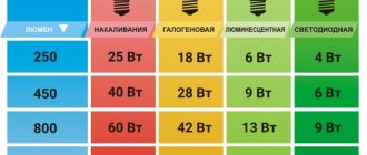
The listed techniques are of particular importance when working with high-frequency radio signals. In particular, to improve conductivity, the surface layer is created from silver, platinum, and other noble metals. The following recommendations are used in practice when creating high-quality audio equipment:
- thin (0.25-0.35 mm) wires are used to transmit signals;
- by braiding the cable, significant distortions of the magnetic field lines are eliminated;
- reliable insulation prevents copper oxidation;
- check for the presence of other lines nearby that can have harmful mutual influence.
Fiber optic communication line
When moving to the microwave range, signals are transmitted through waveguides. Eliminate possible negative manifestations by transmitting data via signals in the optical range.