LM2596 is a voltage converter. With its help, the input value is reduced to 40 V, and the output value is adjusted. At the same time, one current value is maintained - 3 A. The module is excellent for automotive LEDs. The price of the cheapest of these devices is about 40 rubles.
Texas Instruments produces reliable, affordable and easy-to-use controllers. Based on them, Chinese enterprises produce the most inexpensive pulse converters that reduce voltage.
I recommend purchasing at least 10 of these converters. It will cost even less, and you will always find where to use such a device.
Features of LM2596 converters
The most popular application of the device is a voltage source based on a zener diode. It produces a high-quality switching power supply that can withstand the effects of a short circuit. LM2596 - fully complies with the datasheet and all the described parameters.
Another option for using converters is a current stabilizer. The module of this chip connects the LM2596 automotive LED matrix with a power of 10 W, in addition to providing short circuit prevention.
These devices have their own uniqueness. They provide output voltage reduction up to 40 V, requiring only 5 external elements. The voltage of the smart home power bus thus rises to 36 V, and the cross-section of the cables is reduced. In the area of consumption points you need to install such a module and configure it to the required voltage (5,9,12).
Device settings
The microcircuit has the following characteristics:
- Input voltage - from 2.4 to 40 V.
- The output voltage is from 1.2 to 37 V, it can be adjusted and fixed.
- Output current - maximum 3 A.
- Converter frequency - 150 kHz.
- Efficiency at low pressure is 75%, at high pressure it is up to 95%.
Housings
There are 2 types of cases. For one of them, installation inside the hole (TO-220) is used. I like the planar version better, since there the radiator is the board, and there is no need to purchase another external radiator. Mechanically, it is much more stable than the TO-220, which must be screwed to something, for example, to a board. In this case, installing the planar version is much easier.
Dimensions LM2596
I advise you to install the LM2596T-ADJ circuit in the power supply, since it is easier to remove energy from its case.
Using the transceiver
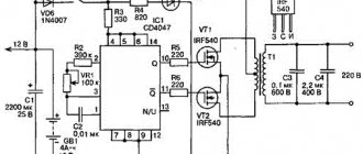
You can assemble a step-down voltage converter with your own hands using a step-down voltage transformer. In this case, three amplifiers will be needed. One of them is installed directly behind the inductor. The other two are located behind the transformer. For successful operation of the device, one filter will be enough. The transceiver is connected to the converter via a choke.
To increase current conductivity, you can use a zener diode. A frequency regulator must be installed if the coil is available at 50 A. In other cases there is no need to share the load. The filter will ensure safe operation of the device.
How linear stabilizers appeared
First you need to understand what the main disadvantage of standard linear converters like the LM78XX is. The main element of such a device is a strong bipolar transistor, which was originally a controlled resistor.
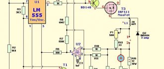
The device is included in a Darlington pair. The main current is driven by the operational amplifier. It increases the difference between the output voltage and the one set by the reference voltage source. It is connected using a standard error amplifier circuit.
Connection diagram of the first converters
So, the resistor is switched on using a converter in a series circuit when there is a load. It controls the resistance to extinguish a certain number of volts at the load. When calculating, it can be established that if the voltage decreases, for example, from 12 to 5 V, the input 12 V is distributed to the load and the stabilizer with a ratio of 7:5.
The “excess” 7 V is extinguished and converted into heat. This leads to cooling problems, and a large amount of power is wasted on this. If the power comes from a wall outlet, there is nothing dangerous about it, but if it comes from a battery or battery, this factor must be taken into account.
Using the described method, it would hardly be possible to produce a converter that increases the voltage. About 30 years ago, calculating such schemes was extremely difficult. The simplest circuit of this type is a 2-cycle converter from 5 to 15 V.
Such a device provides galvanic isolation, but the efficiency of its use of a transformer is extremely low. Only 1⁄2 of the primary winding is actively used.
But this is, let's say, a prototype. Now let's talk about modern devices.
Scheme of a modern converter
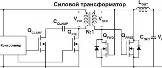
The microcircuit is convenient to use as a step-down converter. a strong bipolar switch is placed inside, you just need to supplement the regulator with a few more components - a fast diode, output and input capacitors, etc.
The LM2596ADJ variation requires a circuit to provide the output voltage: 2 resistors or 1 plasma resistor.
LM2596 looks something like this from the inside:
The PWM signal is controlled by a powerful key from inside the device. Point A has full voltage for x% of the time, and zero voltage for (1–x)% of the time. Fluctuations are smoothed out by an LC filter. It highlights the constant component of the supply voltage.
Inverting converters (type III regulators)
Designed to obtain reverse polarity voltage. In this case, the output signal can be either lower or higher than the input signal. DS/DS microcircuits of inverting type voltage converters contain the same set of basic elements as the above-described devices of types I and II, but their connection is made in a different sequence. A transistor, a diode, a load resistance with a capacitor are connected in series to the power source. An inductive energy storage device is connected between the switching element and the diode.
When the key is closed, energy is stored in the coil. The diode is closed and does not allow electric current to flow to the load. When the transistor is turned off, the EMF of the inductive storage is applied to the section of the circuit with the diode, resistance and capacitor. The rectifier diode passes only voltage pulses with a negative sign, so an inverse voltage is formed at the output, the sign of which is opposite to the sign of the source.
The above options are simplified circuits of DC-DC converters. The vast majority of modern converters have a much more complex design. For example, they are equipped with galvanic isolation, which ensures isolation of the input circuit from the output circuit. They are widely used in power supplies with IGBT transistors and programmable logic controllers. Due to galvanic isolation, a high level of safety and noise immunity is achieved.
In this case, the DC/DC converter circuit can be adjustable, unregulated and semi-adjustable.
How LM2596 works
Inductance does not allow any change in current to pass through it. A high negative self-induction voltage is created, the load voltage is identical to the difference in this parameter for self-induction.
The inductive current and load voltage increase step by step. It is shorted to ground via a diode and decreases. This means that the load voltage has a lower value than the input voltage, and it is affected by the duty cycle of the pulses.
Checking work
When designing or modifying a buck converter circuit (operating in continuous current mode and using PWM), you can use the formulas in this article to calculate the ratings of the main components and the required characteristics. In this case, it is necessary to conduct laboratory tests of the circuit to check the electrical and thermal characteristics. To achieve a working circuit, proper PCB layout and intelligent component placement are as necessary as proper component selection.
Output voltage
The module is produced in 4 versions:
- With voltage - 3.3 V.
- 5 V.
- 12 V.
- LM2596ADJ is an adjustable option.
The customized version is used everywhere, since there are many of them in the warehouses of electronic companies. It is not in short supply, and additions to it are the simplest, these are just 2 cheap resistors. Of course, the 5 V option is also popular.
You can use a DIP switch or turn signal to set the output voltage. In both cases, precise resistors are needed. The voltage is adjusted without the help of voltmeters.
How to smooth out input voltage ripple
It turns out that if you use the LM2596 as a step-down converter, the input capacitor located immediately behind the diode bridge has a small capacitance of 50 to 100 μF.
Output capacitor
If the conversion frequency is high, the input capacitor must also have a large capacitance. A high power consumer will not be able to seriously reduce the performance of a given capacitor during one cycle.
Under no circumstances should tantalum capacitors be used as input or output capacitors. Their datasheet states: “not for use in a power supply circuit,” since they cannot easily tolerate even a small increase in voltage, as well as a high level of pulse current. Use standard aluminum and electrolyte capacitors.
Efficiency, efficiency level and heat loss
The efficiency is not the highest, since the powerful switch is a bipolar transistor. Its voltage drop is not zero, it is 1.2 V. Therefore, the efficiency drops even at low voltages.
The greatest efficiency is possible when the difference between the input and output voltage is 12 V. In other words, if it is reduced by 12 V, most of the energy will be spent on heat.
Let's assume that when 12 V is converted to 5 V, the output current loss in the chip is 1.3 W, the input current is 0.52 A. This is more efficient than a linear type converter, which gives at least a loss of 7 W. Consumption from the input network is twice as much.
LM2577 has a three times lower frequency. It is much more efficient, since losses during transient processes are not so high. But the device requires increased parameters of the inductor and output capacitor, which leads to unnecessary costs.
Selecting a power key
Selecting a power switch (insulated gate field-effect transistor, MOSFET) can be avoided: engineers often bypass this task by selecting regulator ICs with a built-in switch. Unfortunately, for most manufacturers, a large field-effect transistor built into the same package as the converter controller is too expensive. Therefore, converters with a built-in power switch are usually designed for maximum currents from 3 to 6 A. For higher output currents, an external switch must be used.
Before you can select the appropriate product, you must determine the maximum junction temperature (TJmax) and maximum ambient temperature (TAmax) for the foreign switch. TJmax should not exceed 115–120 °C, and TAmax should not exceed 60 °C. A maximum ambient temperature of 60°C may seem high, but buck converter circuits are typically housed in packages where this ambient temperature is normal. The maximum permissible temperature difference for a power switch can be calculated as follows:
Substituting the above values into formula (7) gives the maximum temperature difference for a power switch of 55 °C. The maximum power dissipated by a power switch can be calculated from the permissible maximum temperature difference for the switch:
The type of power switch housing and the amount of copper on the circuit board connected to it affect the thermal resistance between the switch junction and the surrounding environment (θJA). When thermal resistance is not specified in the data sheet, for a standard SO-8 package, 62 °C/W (through conductor connection, with no exposed metal surface at the bottom of the case) is a good approximation. This is true if the printed conductor area is 1 in² with copper plating at a specific gravity of 1 oz per square foot (1 oz copper).
There is no direct proportional relationship between the amount of thermal resistance and the amount of copper connected to the device. The reduction in thermal resistance decreases rapidly as the copper area increases above 1 in². Substituting the value θJA = 62 °C/W into expression (8) gives the maximum permissible switch power dissipation of about 0.89 W.
The power dissipated by a switch depends on its resistance in the conducting state and switching losses. The public key resistance loss can be calculated using the formula:
Since the reference data usually gives the maximum resistance of the open switch only at a temperature of 25 °C, it is necessary to estimate its value for a heated device. As a rule of thumb, a temperature coefficient of 0.5%/°C provides a good approximation for calculating the maximum public switch resistance at any temperature. Thus, the resistance of the public key in a heated state is calculated as:
Assuming that the losses in the key resistance are approximately 60% of all losses in the key, we can substitute into formula (10) and obtain expression (11) for the maximum permissible resistance of the public key at a temperature of 25 °C:
Switching losses make up a smaller portion of the power dissipated by the power switch, but they must be taken into account in the calculations. The following calculation of switching losses provides only a rough estimate and is therefore not a substitute for laboratory experiments. When conducting tests, it is advisable to install a thermocouple on the body of the power switch to monitor the correctness of the calculations.
where CRSS is the pass capacitance of the switch, IGATE is the peak sink-sink gate drive current supplied by the controller, and the power switch is the high-side MOSFET.
Let's assume that the gate is controlled by a current of 1 A (the value is taken from the reference data for the driver-controller) and the pass capacitance is 300 pF (according to the reference data for the power switch). Then from expression (11) we can obtain a maximum RDS(ON)25 °C of approximately 26.2 mOhm. Recalculation and summation of losses in the resistance of the public key with switching losses gives a dissipated power of 0.676 W. Next, you can get a maximum temperature difference across the power switch of 101 C, which falls within the permissible temperature range.
Output current rise
The chip current is quite high, but sometimes even more is required.
Parallel converters configured for the same output voltage. Under such circumstances, simple smd resistors cannot be used in the circuit that sets the voltage, Feedback. Use resistors with an accuracy of 1% or set the voltage yourself using a variable resistor.
If you are not sure that the voltage spread is small, parallel the converters using a small shunt with a resistance of several tens of mOhms. Then the converter with the highest voltage will take on the entire load, and it is not a fact that it will withstand it.
You can take advantage of high levels of cooling using a large heatsink or a large-area multi-layer PCB. This helps increase the current.
There is another option - placing a powerful key outside the chip body. Therefore, it is possible to use a field-effect resistor with a small voltage drop to increase the efficiency and output current.
Diode selection
The limiting factor when choosing a diode is power dissipation. The worst case average power can be calculated using the following formula:
where VD is the voltage drop across the diode at a given output current Ioutmax. (Typically 0.7V for a silicon diode and 0.3V for a Schottky diode.) Make sure the diode you select is capable of dissipating this power. To ensure reliable operation over the entire input voltage range, you must also be sure that the repeating maximum reverse voltage for this diode is greater than the maximum input voltage (VRRM/VINmax). The maximum permissible forward current of the diode must be greater than or equal to the maximum output current.
How is the output current regulated?
This is only possible if we are dealing with an adjustable output voltage in the LM2596ADJ variant. In China, just such a board is produced, which has all kinds of indications. This module can be purchased under the name xw026fr4.
xw026fr4
If you do not want to use a ready-made module, make the device yourself. It is not difficult. There is only one problem - the microcircuit does not control the current, but this can be changed.
A current converter is a current device used in light and laser diodes, galvanic cells, and chargers. You can purchase it in popular online stores.
Transformer with open rectifier
It is very easy to assemble such a converter with your own hands. First you need to install the coil with the primary winding. Choose those that can withstand voltages greater than 30 Ohms. The rectifier itself is mounted adjacent to the tetrode.
It is better to choose open resistors. An amplifier cannot be installed in this circuit. If you are building a 60A device, they should be soldered next to the coil. When everything is ready, the terminal blocks are secured.
USB charger for LM2596
You can build a high-quality portable charger. Set the regulator to a voltage level of 5V, add a USB port to it and provide power to the charger. For example, I have seen a lithium polymer battery that provides 5 amp-hours when the voltage is 11.1 V. This is enough to discharge a typical smartphone eight times without taking into account efficiency. If you take it into account, it will come out about 6 times, no less.
Be sure to close two contacts - D+ and D- USB sockets to inform the phone that it is connected to the charger and the transmitted current is unlimited. If this is not done, the “brain” of the device will accumulate information about its connection to a PC and charging with a current of about 500 mA, that is, very weak. But this current does not compensate for the phone’s energy consumption, and charging the battery is impossible.
Provide a separate 12V input from the car battery with a cigarette lighter socket and use a switch to switch sources. Install an LED to indicate that the device is turned on. Otherwise, you will forget to turn off the battery when it is fully charged, and due to losses in the converter, it will completely die within a few days.
This battery is not the best option, it runs at high current. Find a battery with a higher or lower current, with a smaller size or weight.
lm2596 hw 411
Let's consider another step-down module. Its effectiveness is 80-92%. It is used in various devices that reduce voltage. It can be a power supply, charging, control signal converter. Used in cars to charge equipment.
The DC input voltage is 4-40 V, the output voltage is 1.5-35 V. The highest current value is 3 A, if it is more than 1 A, you need to use additional cooling.
Dc Dc converter
Power supply for electrical equipment is successfully provided using dc dc converters. This device is used in computer technology, communication devices, various control systems, and automation.
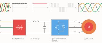
This is a fairly simple idea: DC voltage is converted into AC voltage, usually with a frequency of more than one hundred kilohertz. It increases, and then straightens and enters the load. Such a device is a pulse converter.
The main advantage of the device is its high efficiency, from 60 to 90%. It is also convenient that the spread of input voltages is quite wide.
Adjustable miniature DC/DC converter: we get any voltage from 1 to 24 V from USB
Content
- Introduction
- Appearance, design and circuitry of the DC-DC converter
- Technical tests of DC-DC converter
- Limit operating modes of the converter and short circuit protection
- Converter efficiency
- Results and conclusions
Introduction
When an regulated low-power power source is required in an amateur or even professional radio arsenal, it can be a DC-DC converter powered from a 5-V telephone charger or even from a computer’s USB port.
This is all the more interesting because the amount of telephone chargers from which such a converter can be powered has accumulated in every home a little more than shoe polish at a shoe polish factory. 
The DC-DC converter presented in this review has a built-in voltmeter and allows you to get any voltage from 1 to 24 Volts from the standard 5 Volts (and even a little more, as the test will show).
(image from the seller's page on Aliexpress)
Main technical parameters of the DC-DC converter
| Input voltage | 5 V |
| Output voltage | 1 - 24 V |
| output power | 3 W (max) |
| Efficiency | 94% |
| No-load current consumption | 30 mA |
| Dimensions | 70*26*22 mm |
Characteristics taken from the seller's page; some of them will have to be corrected during the review, including for the better, oddly enough.
The color of the voltage indicator can be red or green (at the consumer's choice).
The price of the converter at the time of review is about 250 Russian rubles ($3.5). You can check the current price or purchase the device here.
Appearance, design and circuitry of the DC-DC converter
The converter is made in the form of a board with a USB connector installed in a case made of transparent blue plastic:
The transparency and glamorous color of the case make a very pleasant impression. Although, in fact, the case here is made transparent not for beauty, but for a functional purpose: so that the readings of the built-in voltmeter are visible.
The body is non-separable, its halves are glued to death.
Near the output terminals on the case there are fins, apparently made so that the case does not slip in the hand. But this fin turned out to be of no use: it is more convenient to pick up the device closer to the USB connector.
The reverse side indicates the functional purpose of the product:
In addition, the polarity of the output terminals and the purpose of the multi-turn variable resistor located on the front side are indicated here.
Through the transparent case you can more or less understand how the converter works.
Behind the fins of the case (on its right side) hides a small 6-legged converter chip - its main part. It is marked B6289M. Apparently, this is one of the clones of the popular MT3608 boost converter chip.
But in this case, our converter as a whole is a buck-boost converter. Judging by the presence of two chokes, the SEPIC circuit is used here, which allows you to turn the boost converter into a buck-boost converter.
An SS34 Schottky diode, which has a low forward voltage drop, is used as a rectifying diode.
The chip has a built-in clock generator with a frequency of 1.2 MHz.
The “many-legged” chip NUVOTON N76E003AT20 is responsible for voltage measurement and indication. This is an analog-to-digital processor with a 12-bit ADC. In this case, this processor is programmed to act as a voltmeter.
Between the indicator and the USB connector there is an element designated F1. This is a fuse (FUSE), it should not trip during normal operation of the device. But the manufacturer still hedged his bets just in case. In addition, it is also strongly recommended to avoid short circuits.
Finally, a blue variable resistor with a ribbed brass handle is responsible for voltage regulation. When rotating it, the main thing is not to apply excessive force when it has reached its final position.
To set the voltage with an accuracy of 0.1 V, you must rotate the knob very slowly and smoothly from the moment the voltage begins to approach the required value. In principle, the mission is feasible.
Technical tests of DC-DC converter
First of all, we check the real limits of voltage regulation and the accuracy of its measurement with the built-in voltmeter.
Set the maximum voltage position:
In total, according to the readings of the multimeter, the voltage was 27.1 V, and according to the readings of the voltmeter of the converter, 25.9 V. In this case, we trust the readings of the multimeter more; because this is some kind of measuring device, after all!
The error of the built-in voltmeter was 4.4%. This is not ideal, but tolerable. When setting the voltage using the built-in voltmeter, you can simply take this fact into account “in your mind”.
Now set the minimum voltage:
In total, according to the multimeter readings, the voltage was 0.61 V, and according to the converter voltmeter readings, 0.5 V.
Here the built-in voltmeter shows the voltage with only one significant digit, and the error is much greater, as much as 18%.
Moral: for very low voltages, it is still better to control its installation using an external device, otherwise the error may be too high.
But the main result is that the output voltage adjustment range not only fell within the stated limits, but even exceeded them! [orchestra plays]
At the same time, based on the circuit design and properties of the converter microcircuit, it can be assumed that the lower limit of the voltage regulation range will always be about 0.6 V, and the upper limit will depend on the spread of resistor values in the circuit, but in any case will be above 24 V.
Limit operating modes of the converter and short circuit protection
Next, we check the maximum output current of the converter at different output voltages. The test was carried out only in the voltage range officially declared by the manufacturer.
The test was carried out when powered by a 5 Volt / 2 Ampere telephone adapter; Moreover, the adapter’s performance at a maximum output current of 2 A was previously successfully tested.
During this test, difficulty arose in determining the exact limit of the beginning of the converter's exit from the mode of stabilization of the specified voltage.
The fact is that if the permissible output power is exceeded, the protection against overload and short circuit in the device does not operate instantly, but gradually. In this regard, the stability limit of the mode was determined a little “by eye”, by a noticeable drop in the output voltage (by more than 0.1 V).
| Output voltage | Maximum output current | Maximum output power |
| 1 V | 1.86 A | 1.86 W |
| 3 V | 1.33 A | 3.99 W |
| 7.5 V | 0.65 A | 4.875 W |
| 9 V | 0.62 A | 5.58 W |
| 15 V | 0.33 A | 4.95 W |
| 24 V | 0.17 A | 4.08 W |
The modes presented here are extreme, and long-term operation in them is highly not recommended (the heating of the case was noticeable).
During this check, it turned out that when setting low voltages and high currents at the output, oscillations with a frequency of about 80 kHz appear at the output, close in shape to a sine:
Here the waveform is shown at an output voltage of 1 V and a current of 0.7 A; but the first signs of such oscillations were observed starting from a current of 0.27 A.
These oscillations are eliminated, as usual, with the help of a capacitor connected to the device externally, but it must be located close to the output terminals of the converter (4.7 µF turned out to be sufficient). If the same capacitor is installed at the far end of a 1 m long cable (for example), then the vibrations are only slightly smoothed out, but not eliminated.
As for protection against short circuits, it cannot be called optimal . At a voltage of 7.5 V, the short circuit current at the output was almost 2.5 A, and the current consumption was 1.55 A.
In this mode, all power consumption is dissipated inside the converter housing, which is dangerous to its life and health if the short circuit is prolonged. During short-term short circuits (2-3 seconds), the converter remains alive (tested).
Converter efficiency
The efficiency was tested in various operating modes of the converter at an output power of 3 W (nominal set by the manufacturer). The exception is the mode with an output voltage of 1 Volt, in which it was not possible to obtain an output power of 3 W.
| Output voltage | Efficiency (Pout = 3 W) |
| 1 V | 44 % |
| 3 V | 63 % |
| 7.5 V | 77 % |
| 9 V | 91 % |
| 15 V | 75% |
| 24 V | 74 % |
The efficiency, even in the most favorable option, did not reach the 94% promised by the manufacturer.
Probably the reason lies in the fact that a more complex device circuit is used than the one for which the converter chip is designed.
It is designed for boost converters; a is used in a buck-boost converter that has additional elements, and, therefore, additional sources of losses.
And, the last question is about pulsations.
Below is a ripple waveform at an output voltage of 7.5 V and a current of 0.4 A:
The ripple range was about 80 mV, i.e. approximately 1% of the output voltage.
In most cases this is an acceptable value; but when using a converter to power devices that are sensitive to interference, it may be necessary to additionally suppress them in the traditional way - using capacitors. In such cases, it is advisable to use capacitors in a combination of “ceramics + electrolyte” and according to the principle “the more, the better.”
Results and conclusions
Even such a simple device made me remember that nothing is ideal in this world. 
The converter turned out to be quite functional and “usable”, but when using it, it is necessary to take into account the features of this device.
First, when working with significant currents and low voltages, you should connect an additional external capacitor near the output terminals (to suppress the “oscillation” at 80 kHz). A large capacitance is not required; 4.7 µF is sufficient.
Secondly, when working with sensitive equipment, it may also be necessary to install additional capacitors that suppress ripple; but with a more “serious” capacity.
Thirdly, we must remember about the inadmissibility of short circuits for any long time.
And finally, fourthly, we must remember that when the converter is powered not from the network adapter, but from the USB port of the computer, there are restrictions on the current supplied by these ports (500 mA for USB 2, and 900 mA for USB 3 ). For an approximate calculation of the permissible output current of the converter, the table given in the review with the efficiency of the device at different output voltages can help.
The ultimate list of pros and cons.
pros:
— wide range of output voltage adjustment, exceeding that declared by the manufacturer;
— possibility of use with short-term excess of permissible output power;
— presence of a built-in voltmeter;
— ability to adjust the output voltage with an accuracy of 0.1 V;
— possibility of power supply from widely used chargers for mobile phones;
— possibility of power supply from USB ports of computers (with power limitations);
- nice appearance, small dimensions and weight.
Minuses:
— low efficiency of protection against short circuits;
— the need for additional capacitors to suppress interference (especially at low voltages and high currents);
— Efficiency is lower than that declared by the manufacturer.
purchase this converter on Aliexpress, check the current price or buy it.
LED Driver
To ensure a stable power supply, you need a special electrical circuit in the form of a power supply unit or driver. It's called led driver.
The electronic circuit ensures stabilization of the voltage and current supplied to the crystal.
This circuit does not automatically support current. It increases with increasing voltage. When its permissible value is exceeded, the crystal will collapse from overheating.
This option is suitable for low-power LED light sources, but it is absolutely not suitable for powerful light emitters. Do not confuse an LED driver with a fluorescent lamp; their operating principles are very different.
