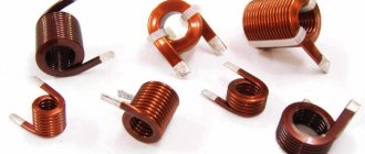
Coil
An inductor is a metal or ferrite core around which several turns of copper wire are wound. The element has the following properties:
- Due to inductance, the rate of change of currents is limited.
- As the frequency of the current increases, the coil is able to increase its resistance (skin effect).
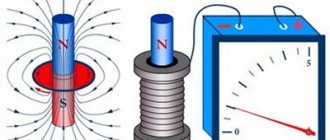
- Creates a magnetic field.
- Increases and accumulates tension.
- Creates a phase shift in alternating current.
- Proportional to the speed of current movement, it creates a self-inductive emf.
All these properties are used in the development of radio receivers, frequency generators, testers, magnetometers and other types of complex equipment.
A magnetic field
This phrase is familiar to us from school. But many have already forgotten what it means. Although each of us remembers that a magnetic field can influence objects, attracting or repelling them. But, besides this, it also has other features: for example, a magnetic field can affect electrically charged objects, which means that electricity and magnetism are closely related, and one phenomenon can smoothly flow into another. Scientists realized this quite a long time ago and therefore began to call all these processes together in one word - “electromagnetic phenomena.” In fact, electromagnetism is a rather interesting and not yet fully understood area of physics. It is very extensive, and the knowledge that we can present to you here is a very small part of what humanity knows about magnetism today.
Now let’s move directly to the subject of our article. The next section will be devoted to the consideration of the inductor design itself.
Design and varieties
All types of inductors have the same design, regardless of their application. The features introduced to obtain individual parameters affect the type of part.
- Solenoid. Component with increased overall length of winding wire. The winding is larger than the diameter of the part.
- Toroidal. In such a coil, the solenoid is made in the shape of a “torus”.
- Multilayer type, has several rows of winding.
- Sectioned. The winding has several divided sections, sometimes made of wire of different sections. The best known coil of this type is the transformer or choke.
- Universal, can combine several winding options at once.
Regardless of design, all coils operate on the same principle.
Principle of operation
An inductor only works when electric current passes through a set of turns of winding. When an element is connected to an electrical circuit, current begins to flow through the coil. Due to the interaction of the wire with the metal core, a magnetic flux is created. The flux is completely proportional to the inductance of the coil and the magnitude of the current. The magnitude of the magnetic flux can be calculated using the following formula: Ф=L×I.
The elements of the formula are:
- “F” is the magnitude of the magnetic flux.
- "L" - induction.
- “I” is the current value.
The number of turns affects the magnitude of the self-induction emf. The turns interact not only with the core, but also with each other, which leads to an increase in EMF.
In an alternating voltage circuit, the magnitude of the EMF can provoke a phase difference between voltage and current up to 90 degrees.
Inductance
The inductance of a coil is its ability to store electricity. This setting depends on:
- Number of turns.
- Wire cross-sections and lengths.
- Design features of the part.
- From the material, length, diameter and shape of the core.
- From the distance between turns.
- Availability of a screen.
In radio electronics it is not customary to indicate the value of inductance. Manufacturers mark parts with the number of turns and indicate the type of core.
Active resistance
An inductor not connected to an electrical circuit has only active resistance.
It is created by a copper wire and depends on its length and cross-section. Active resistance can increase only after being connected to the circuit. In this case, the processes occurring inside the element depend on the type of current.
D.C
A magnetic field is created in an inductor connected to direct current. Its value depends on the number of turns on the core. At the same time, self-induction emf occurs when a magnetic flux moves, which, depending on its strength and speed, pushes part of the voltage onto the surface of the winding.
Due to the formation of EMF, the effect of underestimating the increase in current in this circuit occurs. The current, having a certain strength, is not able to increase instantly, since it is affected by the resistance of the coil. Gradually overcoming the limitation, the current gradually increases and reaches normal values. The rate of this transient process is calculated using the following values:
- "L" - inductance, Henry;
- “R” is the resistance of the electrical circuit, ohms. The value of the entire circuit with the coil is taken;
- “t” — transition process time, sec.
The calculation formula is as follows: t=L/R. This formula also uses the number of turns of the element. For example, t=5×0.7/70=0.05 seconds, where 5 is the number of turns.
For inductors with a primary and secondary winding, the inductive emf proceeds in a slightly different way. This difference is created due to the difference in the sections of the turns. In such a part, the EMF does not prevent the voltage from increasing, but is directed along with the interrupted current in one direction.
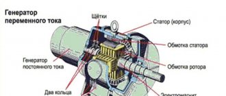
In transformers, the primary winding creates the effect of greatly increasing the voltage at the output contacts. This can be achieved by changing the current on the primary winding. Taking into account the instantaneous change in current strength (simultaneous opening), an emf pulse with an amplitude of tens of kilovolts is induced in the secondary winding. An example of this phenomenon is the ignition coil of a car. Its magnetic field allows it to reach voltages of thousands of volts, despite the fact that it itself runs on a 12-volt battery.
You are interested?
Today there are a lot of scientists interested in magnetism and magnetic phenomena. They study both the magnetic and electrical sides of substances, trying to identify patterns and synthesize powerful magnets with certain desired properties: for example, with a high melting point or superconductivity. All these materials can be used in a huge number of industries.
Let's take an example from the aerospace industry: rockets with ion engines, which create thrust by ejecting ionized gas from a nozzle, are promising for long-distance interstellar flights. The force of the push in such an engine depends on the temperature of the gas and the speed of its movement. Accordingly, in order to give the gas maximum force for acceleration, we need a very strong magnet that accelerates charged particles and also has a very high melting point in order not to melt when the gases exit the nozzle.
Alternating current
Alternating current is very different from direct current. Therefore, its effect on the inductor will also be very different. In addition to active resistance, the coil connected to an alternating current source also has inductive resistance.
The active resistance of a coil not connected to the circuit depends only on the brand of wire, its length and cross-section. When measuring the resistance of a coil disconnected from the circuit, the tester will only show the ability of the wire itself to resist the passage of current. At its core, the active resistance of this element will be equal to 0 + the connected resistor. With this ratio, the coil with its 0 resistance is ideal. For a more accurate measurement of resistance at rest, it is important that the part is completely disconnected from the circuit. When measured on the circuit, the resistance will be increased due to the parameters of other radio components.
Inductive reactance occurs only after connecting the coil to an alternating current circuit. It depends on the frequency of the current and the number of turns. Inductive reactance can be determined using a simple formula: XL=2×π×f×L. In this expression:
- "XL" - inductive reactance.
- “π” is the number “pi” equal to 3.14.
- “f” is the frequency response of the current.
- "L" - inductance.
When alternating current passes through the turns of the coil, the effect of displacement of a fraction of the currents by magnetic fluxes is created. This property is similar to the effect of direct current. The main difference lies in the lateral displacement. The magnetic field of each turn exerts pressure on the field of the next turn. Thus, the active resistance increases.
This effect increases depending on the cross-section of the wire, its conductivity and temperature. The proximity effect, which greatly influences the increase in active resistance, is reduced by selecting the cross-section of the winding wire. Reducing the proximity effect is unacceptable by increasing the distance between turns. This approach affects the reactance and power of the magnetic field.
As a result, the active resistance when connecting the coil to an alternating current source has the following properties:
- Interacts with inductive reactance parameters.
- Capable of reducing the speed of magnetic flux.
- Creates a phase shift in voltage and current.
- When operating at high currents, the active resistance of the coil increases the temperature of the component itself and the entire circuit as a whole. Heating often occurs due to weak contacts, incorrectly selected output wire cross-section and heavy load in the general network.
In electrical engineering, there are a number of types of shielded inductors. Such screens are often made of steel or aluminum. They are necessary to reduce the impact of the magnetic field on nearby circuit elements. Screens also have the opposite function. With their help, the coil protects itself from the influence of adjacent circuit components. In this way, manufacturers can reduce some of the interference. The effect of the magnetic field of an unshielded coil can be heard, for example, if you bring the element to a switched on radio. The screen also has one significant drawback. It greatly increases the active resistance of the part itself.
Professional testing
You will need professional grade equipment.
The optimal solution would be to designate a separate stand for checking coils. This way it will be possible to set different speed modes for the rollers, simulating different types of work. When interacting, you need to ensure that a spark is constantly maintained, regardless of the operating mode. Before carrying out the test, you need to make sure that this power supply is connected correctly, otherwise you may receive unreliable data, which will prevent the determination of problems.
A reel is a small component of vehicles. Even small deviations from normal performance can lead to serious engine problems.
Author of the article Shamraev Nikolay Pavlovich Rate the article (votes: 41, average: 4.8 out of 5) We recommend reading How to check a thyristor with a multimeter How to check a thyristor and triac Ku202N with a multimeter How to make a sword How to make a sword out of wood with your own hands Comments on the article
Resistance measurement and calculation formula
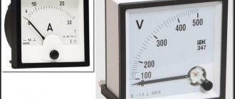
The active resistance of the inductor can only be measured in a de-energized state. This is done using a multimeter.
- The multimeter must be switched to ohmmeter mode.
- Connect the red measuring probe to the first output of the coil.
- Connect the black test lead to the second output.
- The device will only show the active resistance of the winding.
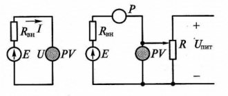
Using a tester, you can only determine the integrity of the turns. If the element is connected to a live circuit, then the resistance value is found by a simple calculation using the formula: Z=U/I.
To calculate using this formula, using a tester, first determine the value of current (I) and voltage (U). Active resistance is measured in Ohms.
Knowing the formula for calculating active and inductive resistance, the total resistance of the element can be found using the formula:
Z=2×(R×R+XL×XL)
In this expression, R is resistance and XL is inductive.
About real capacitor
A real capacitor has two resistances at the same time: active and capacitive. They should be considered connected in series.
The voltage applied by the generator to the active resistance and the current flowing through the active resistance are in phase.
We advise you to study Magnetic Field Energy Density
The voltage applied by the generator to the capacitance and the current flowing through the capacitance are shifted in phase by 90. The resulting voltage applied by the generator to the capacitor can be determined using the parallelogram rule.
At the active resistance, the voltage Uact and current I are in phase. At capacitive reactance, the voltage Uc lags the current I by 90. The resulting voltage applied by the generator to the capacitor is determined by the parallelogram rule. This resulting voltage lags behind the current I by some angle φ, always less than 90.