In the development of the electronic theory of conductivity of metals, the effect discovered by the American physicist E. G. Hall in 1879 became important. According to the Drude-Lorentz theory, the electric current in metals is a flow of free electrons caused by an external emf. The quantitative characteristic of the flow is the current strength
i = Δ q Δ t = en S vi=\frac{\Delta q}{\Delta t}=enSv i=ΔtΔq=enSv
or current density
j = i S = env , j=\frac{i}{S}=env, j=Si=env,
where e e e – electron charge; nnn – concentration of free electrons; vvv – average speed of ordered movement of electrons.
Notable in this expression is the dependence of the current density on the concentration of free electrons.
The significance of the Hall effect is that it can be used to determine the electron concentration in metals.
From Lorenz to Hall
The Hall effect is an extension of the Lorentz force, which describes the force acting on charged particles - such as an electron - moving in a magnetic field. If the magnetic field is directed perpendicular to the direction of motion of the electrons, the electron is subject to a force that is perpendicular to both the direction of motion and the direction of the magnetic field.
The Hall effect refers to a situation in which the Lorentz force acts on electrons moving in a conductor such that a potential difference - or in other words, voltage - occurs between the two sides of the conductor.
It should be noted that the arrows in the second figure show the directions of normal current flow, which means that the electrons are moving in the opposite direction. The direction of the Lorentz force is determined by the right-hand rule, which takes into account the direction of motion of the electron relative to the magnetic field. In the first picture, the electron is moving to the right, and the Lorentz force is directed upward. In the second picture, the electrons are moving to the left and the Lorentz force is downward, and thus negative charge accumulates on the bottom side of the conductor. The result is a potential difference that occurs between the top and bottom edges of the conductor, with the top edge being more positive than the bottom. This potential difference is called the Hall voltage:
\[U_{Hall}=-\frac{IB}{eρt}\]
This formula, which is applied to a conductive plate, tells us that the Hall voltage depends on the magnitude of the current (I) flowing through the conductor, on the magnetic induction (B), on the elementary charge of the electron (e), on the number of electrons per unit volume (ρ) and on the thickness of the plate (t).
Applications
Quantization of Hall conductance ( g x y = 1 / r x y { Displaystyle G_{xy} = 1 / R_{xy)) ) has the important property of being extremely accurate. It was found that actual measurements of Hall conductivity are integer or fractional multiples of e
2/
hour
to almost one part per billion.
This phenomenon, called exact quantization
, is not really understood, but has sometimes been explained as a very subtle manifestation of the principle of gauge invariance.[4]
This allowed the definition of a new practical standard for electrical resistance, based on the quantum of resistance given by von Klitzing's constant p
K. It is named after Claus von Klitzing, the discoverer of precise quantization. The quantum Hall effect also provides an extremely accurate independent determination of the fine structure constant, a fundamentally important quantity in quantum electrodynamics.
In 1990, the conditional p
K-90 = 258120.807 ohms has been specified for use in resistance calibrations throughout the world.[5]
On November 16, 2022, at the 26th meeting of the General Conference of Weights and Measures, it was decided to establish the exact values of h
(Planck's constant) and
e
(elementary charge),[6] replacing the 1990 value with an exact constant value
p
K =
h
/
e
2 = 25812.80745… Ω.[7]
Using the Hall effect
The voltages generated by the Hall effect are small relative to the effects of noise, offset and temperature that typically affect the circuit, and thus true Hall effect sensors were not widespread until the advent of semiconductor technology enabled the creation of components with a high degree of integration, which included both the Hall element and the additional circuitry necessary to amplify the Hall voltage. However, Hall effect sensors are limited in their ability to measure small currents. For example, the sensitivity of the ACS712 from Allegro MicroSystems is 185 mV/A. This means that a current of 10 mA will produce an output voltage of only 1.85 mV. This voltage may be acceptable if the circuit is low noise, but if a 2 ohm resistor is included in the current path, the result may be 20 mV, which is much better.
The Hall effect is used in various sensors; devices based on the relatively simple relationship between current, magnetic field and voltage can be used to measure the position, speed and strength of a magnetic field. In this article, we will focus on devices that measure current through the Hall voltage generated when the magnetic field created by the current being measured is concentrated in the Hall sensor element.
Areas of use
The Hall method finds its application in many areas of human activity, for example, it makes it possible to determine the indicator of mobility and concentration n. h., and sometimes the type of charge carrier itself. The Hall effect in semiconductors and metals is considered an excellent way to study semiconductor properties, due to the above-mentioned ability to determine various characteristics of charge carriers.
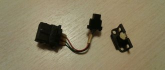
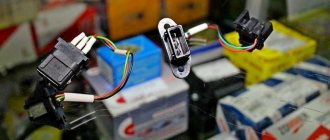
A Hall sensor is a device that operates on the basis of this effect. It measures such a characteristic of the m.p. as tension. Such sensors find their application in valve-type and brushless motors, as well as in electric motors. Their function is to provide feedback regarding the position of the rotor, and their function is similar to that of a commutator DC motor. Such devices are often called rotor position sensors.
Places of application:
- Electronic ignition system in internal combustion engines.
- Fans of computers and devices similar to them, as well as disk drives.
- Electronic compasses of smartphones, as performers of physical work, have precisely such sensors located in the magnetometer.
- Devices aimed at measuring non-contact current also use a Hall sensor.
- Ion-type rocket engines operate on the basis of e-Hall.
Advantages and disadvantages
The characteristics of different Hall effect current sensors vary greatly, so it is difficult to summarize the advantages and disadvantages of using the Hall effect relative to another common method of measuring current; namely, inserting a precision resistor into the current flow circuit and measuring the voltage drop that appears across it using a differential amplifier. In general, Hall effect sensors are valued for their "non-interference" properties and for providing electrical isolation between the current flow path and the sensing circuit. These devices are considered to have no effect because no significant resistance is inserted into the current path, and thus the circuit behaves as if there were no sensor at all when making measurements. An additional benefit is that the sensor dissipates minimal power; this is especially important when measuring large currents.
In terms of accuracy, currently available Hall sensors can achieve a minimum error of 1%. A well designed resistor based sensor can give better results, but one percent is usually sufficient for high current/voltage applications where Hall sensors are suitable.
Disadvantages of Hall sensors include limited frequency range and high cost. The ACS712 operates up to 80 kHz, and the Melexis MLX91208 range, which is positioned as “wideband,” is limited to the upper limit of 250 kHz. A resistive current sensor with a high-speed amplifier, on the other hand, can work well in the megahertz range. Additionally, as discussed above, the Hall effect is inherently limited when it comes to measuring small currents.
How to check battery capacity
There are several effective ways to find out the capacity of any battery. Some of them do not require special expenses or special equipment, but only simple mathematical calculations.
The accuracy of such methods is not as high as when using special devices, but they allow you to find out the approximate capacity. For many this will be enough.
So, to calculate the capacitance using the free method, you need to use a known current. The battery specifications contain information about the current. A battery with a capacity of 3600 is charged for 36 hours with a current of 100 mAh. This means that the final result is obtained by multiplying two components: time and current. Therefore, knowing how much is required for a full charge, you can find out the capacity.
To measure capacity in another way, you will need to spend money. There are many smart chargers that can quickly measure capacity. They can be purchased at a specialty store or on aliexpress. They are used to measure various indicators, not just capacity.
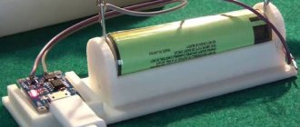
A device that measures real capacitance
To implement the third method, you will need such parts as a battery, a watch, an ammeter with a flashlight. You need to insert the battery into the flashlight and turn it on at maximum power. An ammeter is needed to measure current. If the flashlight shines for 20 hours with a current consumption of 100 mA, then we get 20 * 100 = 2000 mAh.
Insulation
One of the main advantages of Hall sensors is electrical isolation, which in the context of circuit and system design is called galvanic isolation. The principle of galvanic isolation is used whenever a design requires two circuits to be coupled in a manner that prevents any possibility of electrical current flowing between them. A simple example is where a digital signal is transmitted through an opto-isolator, which converts voltage pulses into light pulses and thus transmits data optically rather than electrically. One of the main reasons for implementing galvanic isolation is to prevent problems associated with ground loops:
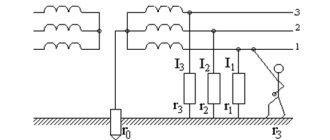
Basic circuit design principles assume that interconnected components share a common ground point, which is assumed to be 0 V. In real life, however, ground consists of conductors that have non-zero resistance, and these conductors serve as the return path for current to flow from the circuit back to the power source. Ohm's Law reminds us that current and resistance will produce voltage, and this voltage drop in the return path means that the ground in one part of the circuit is not exactly the same potential as the ground in another part of the circuit. This difference in ground potential can cause problems ranging from minor to catastrophic.
To prevent DC current from flowing between the two circuits, galvanic isolation is used, allowing the circuits to successfully communicate with different ground potentials. This is especially true for current measurements: a low-voltage sensor and processing circuit may be needed to monitor large, highly variable currents, such as in a motor drive circuit. These large, rapidly changing currents will cause significant voltage fluctuations in the return path circuit. The Hall effect sensor allows the system to monitor the drive current and protect the high-precision sensor circuitry from these harmful ground vibrations.
Magnetic sensors
The main advantage of using magnetic field sensors is their non-contact operation. They are analog and discrete. The first type is considered classic. It is based on the principle that the stronger the magnetic field, the greater the voltage. In modern instruments and devices, this type is practically no longer used due to its significant size. The digital sensor is built on the “key” operating mode and has two stable positions. If the induction force is insufficient, it does not work.
You might be interested in The design of a thermocouple, its types and operating principle
Discrete Hall elements are divided into two types:
- unipolar - the operation of which depends on the pole of the magnetic field;
- bipolar - the sensor state switches when the magnetic pole changes;
- omnipolar - react to the action of magnetic induction in any direction.
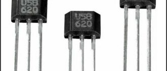
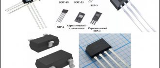
Structurally, the sensor is an electronic device with three terminals. It can be produced either in a standard DIP, DFN or SOT version, or in a sealed version: for example, 1GT101DC (sealed), A1391SEHLT-T (DNF6), SS39ET (SOT), 2SS52M (DIP).
Device characteristics
Manufactured sensors using the Hall phenomenon, like any electronic radio components, are characterized by their own parameters. The main ones are the type of device and supply voltage. But, besides this, the following technical characteristics are distinguished:
- The magnitude of the measured induction. It is measured in gauss or millitesla.
- Sensitivity - determined by the value of the magnetic flux to which the sensor responds, the unit of measurement is mV/Gauss or mV/mT.
- Zero magnetic field voltage is the value of the potential difference corresponding to the absence of a magnetic field.
- Zero drift is a change in voltage that depends on temperature. Indicated as a percentage deviation from a temperature of 25 °C.
- Sensitivity drift is a change in sensitivity caused by a change in temperature.
- Bandwidth - level of sensitivity reduction in 3 dB steps.
- On and off induction is the field strength value at which the sensor operates stably.
- Hysteresis is the difference between the inductions of on and off;
- Response time - characterized by the time interval of transition from one stable state to another.
Manufacturing of devices
The material from which the Hall element is made must have high mobility of charge carriers. To obtain the highest voltage value, the substance should not have high electrical conductivity. Therefore, in the production of devices the following are used: selenide, mercury telluride, indium antimonide. Thin-film sensors are produced by evaporating a substance and depositing it on a substrate. It is used as mica or ceramics.
Sensors are also made from semiconductors - germanium and silicon. They are doped with arsenic or phosphorus antimony. Such devices have a low dependence on temperature changes, and the magnitude of the emf generated by them can reach one volt.
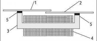
A typical manufacturing process for a Hall plate sensor consists of the following steps:
- cutting the plate to the required size;
- surface grinding;
- formation of symmetrical leads by soldering or welding;
- sealing.
One of the main advantages of sensors made using this effect is electrical isolation (galvanic isolation), which makes their use convenient and safe.
Common Mode Voltage
Another important application of Hall sensors is to measure currents when operating at high voltages. In a resistive current sensor circuit, a differential amplifier measures the difference between the voltages on one side of the resistor and the other. The problem occurs when these voltages are large compared to ground potential:
Real amplifiers have a limited "common mode range", which means the device will not function properly, the difference between the input voltages is small, and the difference between them and ground is very large. The common-mode input voltage ranges of current-sensing amplifiers are typically within 80 or 100 V. Hall sensors, on the other hand, can convert current to voltage without reference to ground potential in the circuit being measured. Therefore, as long as the voltage is not high enough to cause physical damage, common mode voltage does not affect the operation of the Hall effect sensor.
Original article
- Robert Keim. Understanding and Applying the Hall Effect